Love Wave Propagation in a Piezoelectric Composite Structure with an Inhomogeneous Internal Layer
Yanqi Zhao, Peng Li, Guochao Fan, Chun Shao

TL;DR
This paper studies how Love waves propagate in piezoelectric materials with an inhomogeneous layer, offering insights for designing surface wave devices and sensors.
Contribution
The study introduces a power series method to analyze Love wave propagation in functionally graded piezoelectric materials with material inhomogeneity.
Findings
Material inhomogeneity affects phase velocity, electromechanical coupling, and displacement distribution of Love waves.
Piezoelectric damage and material bonding influence higher mode appearance and fundamental mode region in electrically open and shorted cases.
Abstract
An inhomogeneous thin internal stratum sometimes exists between two dissimilar materials, which is usually caused by non-uniform thermal distribution, interaction of different media, diffusion impurity or material degeneration and damage. In this paper, it is considered as a functional graded (FG) piezoelectric material in surface acoustic wave devices, and we investigate its effect on Love wave propagation within the framework of the linear piezoelectric theory. Correspondingly, the power series technique is presented and applied to solve the dynamic governing equations, i.e., two-dimensional partial differential equations with variable coefficients, with the convergence and correctness being proved. In this method, the material coefficients can change in random functions along the thickness direction, which reveals the generality of this method to some extent. As the numerical case,…
Click any figure to enlarge with its caption.
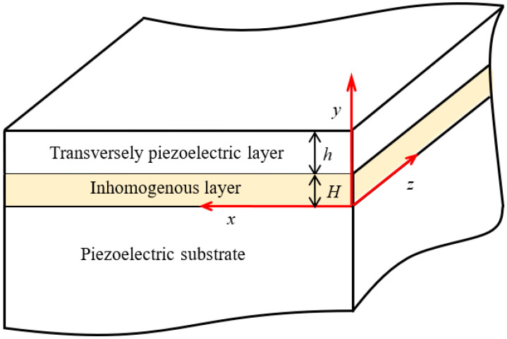 Figure 1
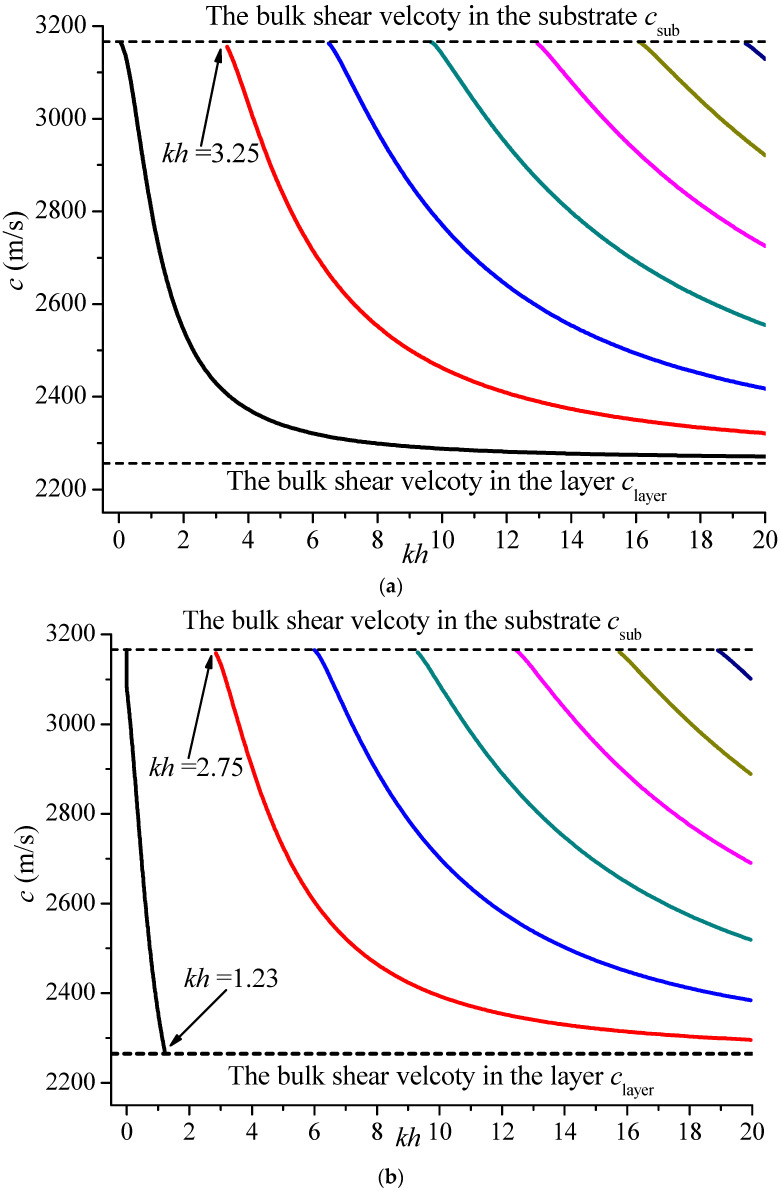 Figure 2
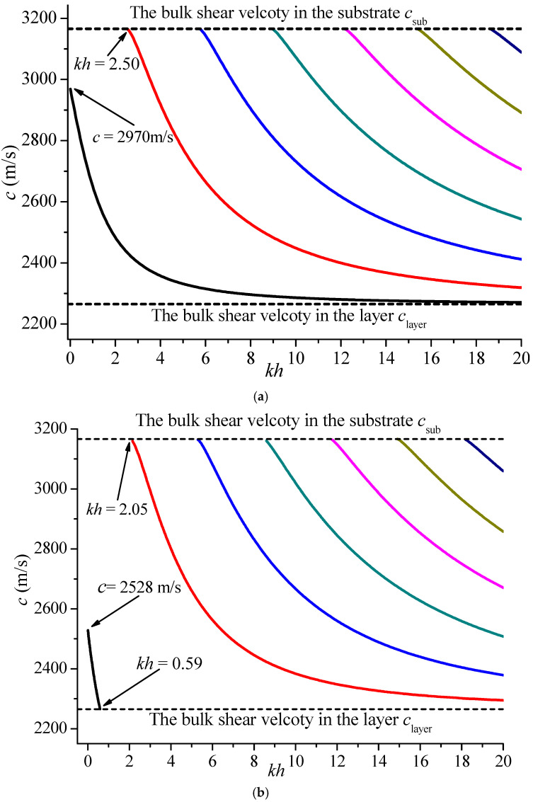 Figure 3
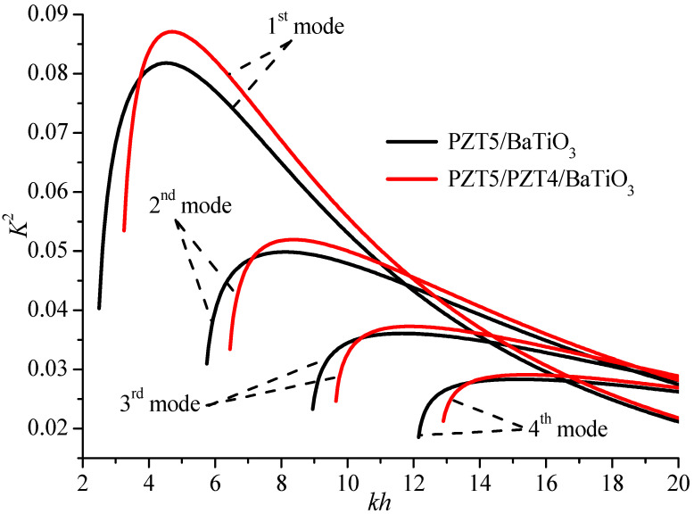 Figure 4
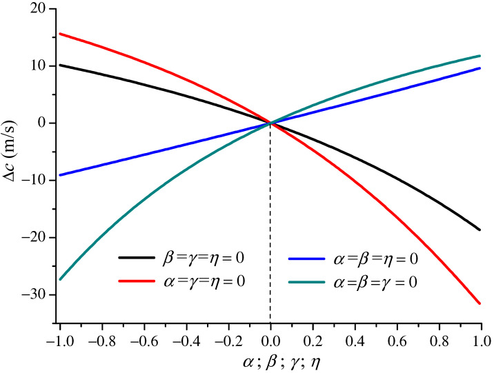 Figure 5
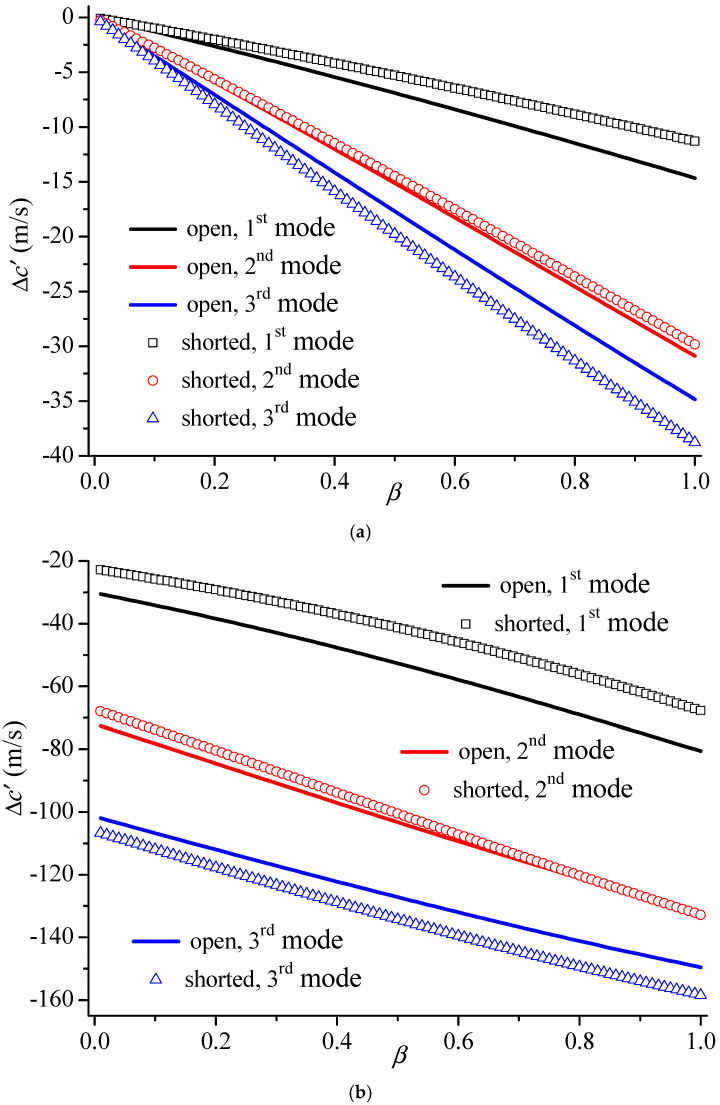 Figure 6
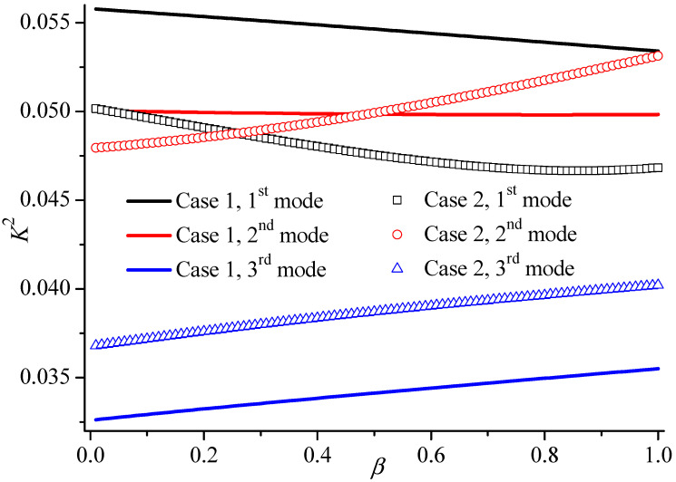 Figure 7
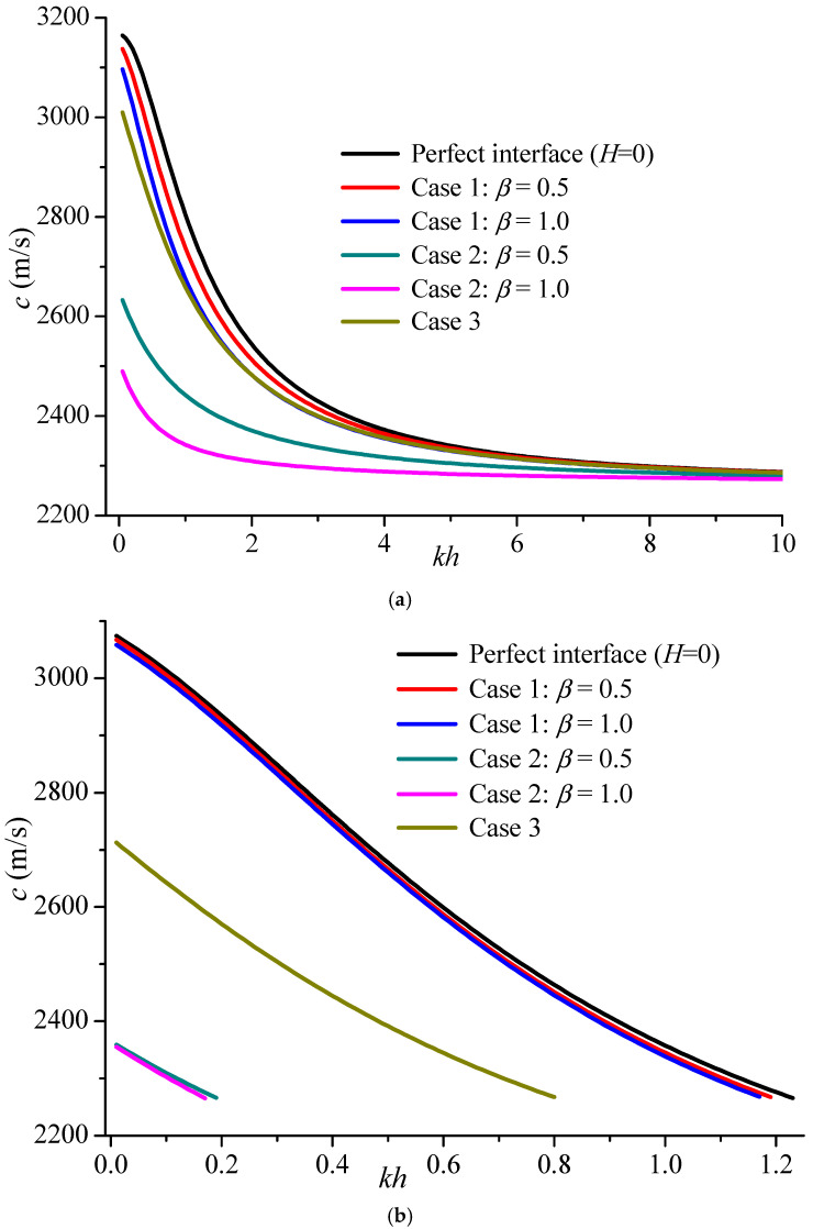 Figure 8
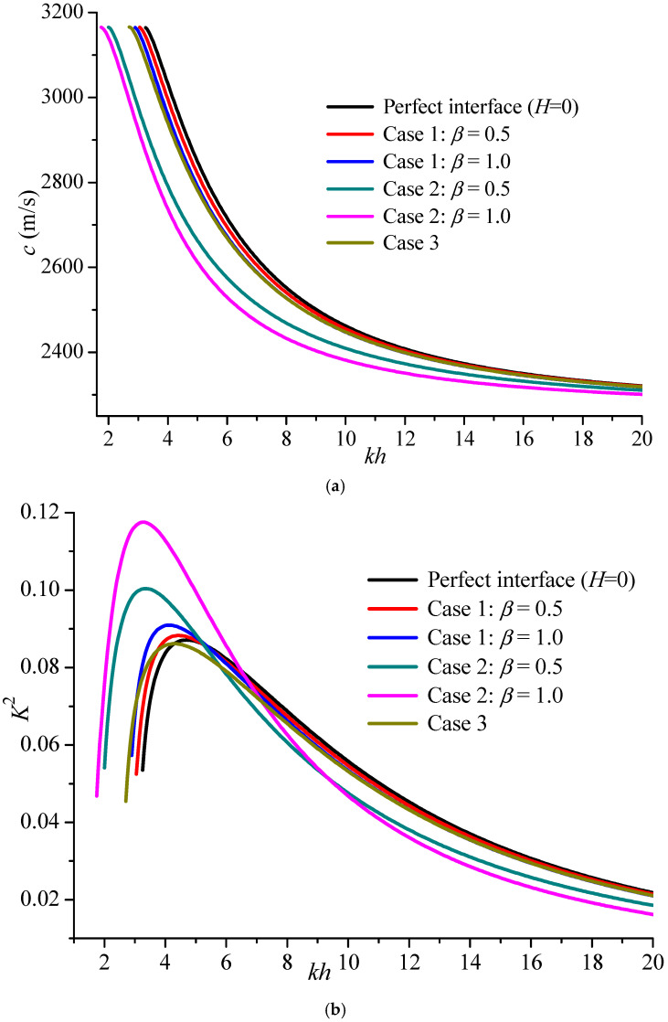 Figure 9
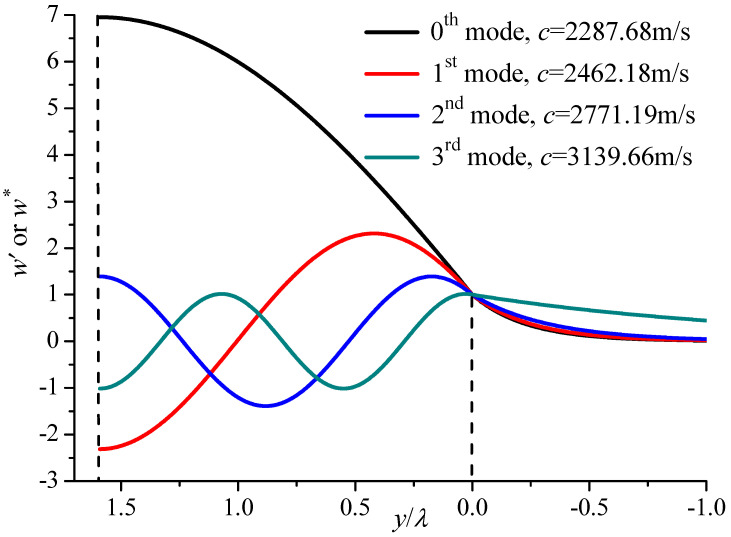 Figure 10
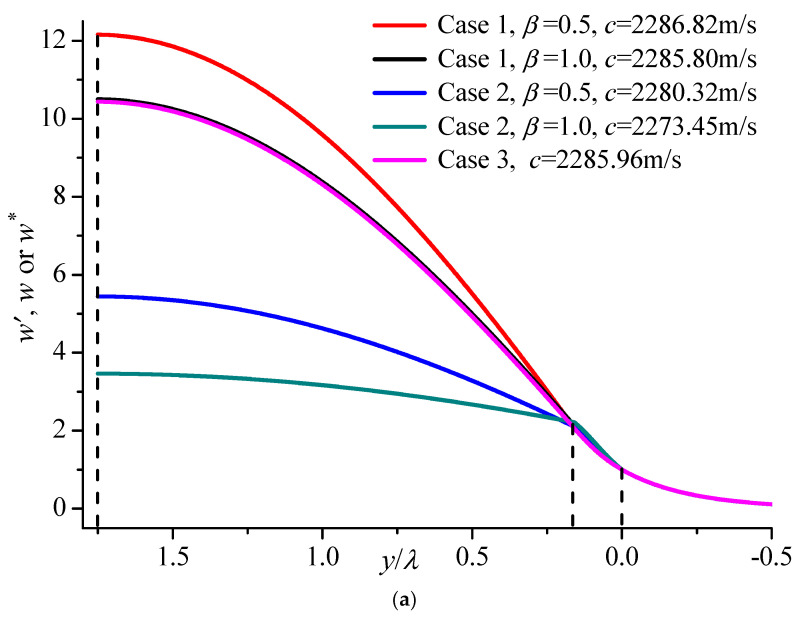 Figure 11
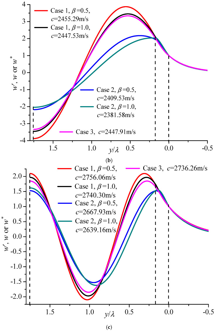 Figure 12
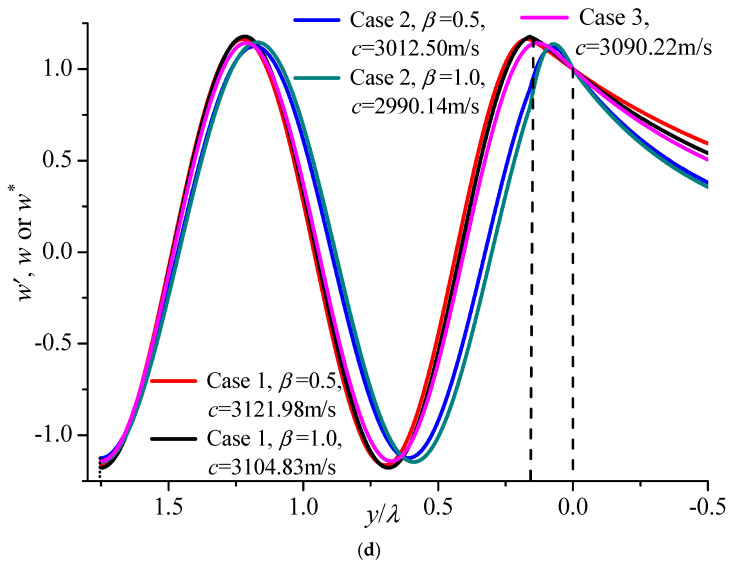 Figure 13
- —National Natural Science Foundation of China
- —key task project for joint research and development of the Yangtze River Delta Science and Technology Innovation Community
- —State Key Laboratory of Mechanics and Control for Aerospace Structures (Nanjing University of Aeronautics and Astronautics)
Peer Reviews
No public reviews on file for this paper yet. If you reviewed it on a platform where reviews are public (OpenReview, ICLR, NeurIPS, ICML), you can paste yours below so the community can read it here.
Videos
No videos yet. Explain this paper in a talk, walkthrough, or lecture? Add one.
Taxonomy
TopicsThermoelastic and Magnetoelastic Phenomena · Numerical methods in engineering · Ultrasonics and Acoustic Wave Propagation
1. Introduction
The Love wave, established by A. E. H. Love in 1911, plays an important role in surface acoustic wave (SAW) devices, including filters, delay lines, oscillators, amplifiers, and so on [1,2,3,4]. It has only one shear horizontal displacement component, which perpendicular to the propagation and penetration directions and travels in a thin sensitive layer deposited on a substrate when the wave speed is larger than the bulk shear velocity in the layer and smaller than that in the substrate [5,6]. The penetration is comparable with the wavelength, and the energy mainly concentrates on the surface, which leads to its high mass sensitivities at a certain frequency and is especially suitable for liquid sensors [2,6,7].
In order to improve the properties of Love waves, a stratum of finite depth has been added as an internal middle layer in the layer/substrate composite structure mentioned above [8,9,10]. For example, to avoid defects and brittleness, an extra piezoelectric ceramic or polymer layer is embedded between the layer and the substrate [8]. Additionally, an additional thin SiO_2_ [9,11] layer has been inserted as a middle layer to realize a relatively low or even zero temperature coefficient of delay, which can efficiently improve SAW device stability.
From the perspectives of device fabrication, an internal layer sometimes cannot be avoided due to various causes, such as non-uniform distribution of temperature, interaction of different media, diffusion impurity, piezoelectric damage, and so forth [12]. In addition, when bonding the layer on the substrate surface, an interphase or transition, with a thickness typically in the range of 30–240 nm, exists across the interface [13,14,15]. For instance, a homogeneous internal epoxy-bonded layer was predicted in a copper-aluminum layered specimen by Wu et al. [16,17], and its effect on laser-generated surface wave dispersion was investigated. However, the bonding layer in these previous works [13,14,15,16,17,18,19,20] is usually considered homogeneous, with its material properties keeping constant along the thickness and length direction. Due to damage, interface connection or other external factors, once this layer occurs, it is difficult to maintain the homogeneity of the material properties of the internal stratum. Hence, it is essential to investigate the influence of an inhomogeneous internal stratum caused by material damage or interface connection on wave propagation, which is the innovation of this contribution.
For waves in an inhomogeneous or functional graded (FG) piezoelectric material, the mechanical field is coupled with the electrical field, which is hardly decoupled. This is because the dynamic governing equations belong to second-order partial differential equations with variable coefficients. Solving this kind of equation directly is a difficult task. The Wentzel–Kramers–Brillouin method can be used to solve it. But this method is only suitable for large wave numbers [6,21,22]. The stiffness matrix method [23,24], state-space method [25,26], reverberation-ray matrix method [27,28], Legendre polynomial approach [29,30] and hybrid numerical method [31] can be used to solve it. However, these methods are based on the transfer matrix method, in which the inhomogeneous layer is divided into many sub-layers in advance and the material is assumed homogeneous in these sub-layers. The computational efficiency is dependent on the number of sub-layers, and the computing process is very complex. In order to solve the second-order partial differential equations with variable coefficients caused by material inhomogeneity, the power series technique is presented, with its convergence and correctness further validated theoretically and numerically, which is another innovation of this paper. To some extent, this method is general, with the material parameters changing arbitrarily, and the solution is available for any wave number without any limitation.
Firstly, the description of the problem and Love wave solutions are presented in Section 2. After the correction and convergence are proved, the effect of functional graded parameters is systematically discussed in Section 3. Subsequently, an inhomogeneous stratum caused by piezoelectric damage and a transition buffer layer is investigated as the potential engineering application. Finally, some conclusions are drawn. Considering that the material tensors of crystals with 6 mm symmetry possess the same structures as polarized ceramics, the present method and analysis are still valid for 6 mm piezoelectric crystals, e.g., ZnO and AlN.
2. Statement of the Problem and Solutions
An SAW device usually consists of two layers, i.e., an upper piezoelectric sensitive layer and a substrate. The piezoelectric sensitive layer is so thin that the substrate is viewed as a half-space for analysis. Therefore, we consider wave propagation in a three-layer composite structure consisting of a transversely piezoelectric sensitive layer and a piezoelectric half-space substrate with an inhomogeneous internal stratum layer, as shown schematically in Figure 1. This inhomogeneous internal stratum is considered as an FG piezoelectric material layer. For the piezoelectric medium, the linear piezoelectric constitutive equations can be expressed as follows [32,33,34,35].
where σ_ij_ and D_i_ are the stress tensors and electrical displacement vector. c_ijkl_, e_lij_, ε_il_ are the elastic coefficients, piezoelectric coefficients, and dielectric permittivity, respectively. u is the displacement vector, and φ represents electrical potential function. An index after a comma denotes partial differentiation with respect to the coordinate. For the piezoelectric materials poled in the z direction in Figure 1, h and H are the thickness values of the top layer and non-uniform middle layer, respectively. The propagation of Love waves may be represented by displacement components, and the electrical potential function as follows [6,8,9,12,19].
Thus, the governing equation can be expressed as follows [19,36,37].
where ρ is the mass density, is the two-dimensional Laplace operator, t is time, and the dot means time differentiation.
2.1. Solutions for the Substrate y < 0
Here, we use the star and prime symbols to distinguish the different parameters in the substrate y < 0 and sensitive layer H < y < (H + h), respectively. Given that the displacement and the stress are finite when y⟶∞, the solutions for the Love wave propagation in the positive x direction can be expressed as
where and are undetermined constants, , and k is the wave number in the x direction. is the bulk shear velocity in the substrate with . Using Equation (1), the stress component and electrical displace can be obtained as
2.2. Solutions for the Top Piezoelectric Layer H < y < (H + h)
The Love wave solutions in the top piezoelectric layer are
where , , , and are undetermined constants, and . is the bulk shear velocity in the layer with . The phase velocity of the Love waves satisfies , which ensures and are all positive. Finally, the corresponding stress and electric displacement in the top piezoelectric layer are
2.3. Solutions for the Inhomogeneous Internal Region 0 < y < H
Sometimes, is assumed that all material coefficients of the middle layer change in the same exponential function variation [38,39], which can provide convenience for decoupling the mechanical components from the electrical field. However, this variation is impossible in actual life. In this contribution, the material variation tendency is not limited, which is the highlight of this paper. No matter what variation form the material parameters of the inhomogeneous layer take along the y direction, they can be expressed in the power function theoretically by using Taylor’s series, which means
Theoretically, material coefficients can change in random functions along the thickness direction, which depends on the truncation of the power series and the coefficients , , and . For analysis simplification, the elastic, piezoelectric, and dielectric coefficients as well as the mass density of the layer are all assumed to change linearly in the y direction, i.e.,
where the coefficients α, β, γ, and η indicate the profile of the corresponding material gradient along the y-axis, and the quantities with superscript “0” are the values of these parameters at y = 0. This linear pattern can be used to calculate the effect of the internal stratum induced by internal temperature variations [40], and the investigation of the graded factor on the Love wave propagation properties is of great importance.
The displacement w and electrical potential φ in the functional graded middle layer 0 < y < H can be expressed as
Thus, the governing equations are
Equation (11) contains two second-order partial differential equations with variable coefficients with respect to W and Φ. Different from previous works [21,31], an easy numerical solution is developed, which is based on the power function expansion technique along the y direction [41,42,43,44], i.e.,
Substituting Equations (9) and (12) into Equation (11) yields
By equating the terms of in Equation (13) to zero, we can obtain the corresponding recursive relationships of a_n_ and b_n_, i.e.,
Here , , and are the respectively piezoelectric coupling constant, effective piezoelectric stiffness, and bulk shear wave velocity when the middle layer is homogeneous. a0, a1, b0, b1 are undetermined coefficients. Once these parameters are calculated, a_n_ and b_n_ (n > 1) can be obtained using Equation (14). Based on the given solutions, the solutions for the FG piezoelectric middle layer are
Similarly, the stress and electrical displace components are
2.4. The Electric Field in the Air y > (H +h)
Usually, the space above the upper surface of the layer is air. Therefore, the electrical potential function φ0(x, y) satisfies the Laplace equation:
Given that the electrical potential function in the air satisfies the governing Equation (17), the solutions can be expressed as
where F0 is also an arbitrary constant, and ε0 is the dielectric permittivity in the air. It should be stressed that the layer’s surface is directly attached to the air in this paper. When facing a sorption process or surface contamination, Equation (17) is not applicable anymore.
2.5. The Phase Velocity Equations
The traction-free surface at y = H + h requires
The electrical boundary conditions at y = H + h are
for the electrically open case and
for the electrically shorted case.
The continuity conditions at y = H and y = 0 are, respectively,
Substituting the displacement and electrical potential expressions in Equations (4), (6), and (15) as well as their corresponding stress and electric displacement components in Equations (4), (7), and (16) into Equations (19)–(21) yields the following linear homogeneous algebraic equations for coefficients , , , , a0, a1, b0, b1, and :
Non-trivial solutions can only exist when the determinant of the coefficient matrix of Equations (22), (23a) and (24) is equal to zero, which yields the phase velocity equation of Love wave propagation in this structure for the electrically open case:
with
Here , and all the other terms are equal to zero. Similarly, we can obtain the phase velocity equation of the Love wave for the electrically shorted case by using Equations (22), (23b) and (24), which have the same expression as Equation (26) if ε0 = ∞.
3. Numerical Simulations
For revealing the Love wave behavior in the composite structure shown in Figure 1 and graphically showing the effect of the inhomogeneous middle layer, the following material system is considered, i.e., a semi-infinite BaTiO_3_ substrate carrying a PZT4 layer in the middle and a PZT5 layer on the top. The elastic and piezoelectric constants, the mass density and the dielectric constants are summarized in Table 1 [45,46]. For solving Equation (26), we adopt an iterative procedure for the numerical computations. For an initial value of c, the determinant of Equation (26) is estimated. A fixed but small increment is added each time until the value of the determinant changes its sign.
3.1. Convergence of the Power Series
Firstly, the series convergence is examined. Table 2, Table 3 and Table 4 show the phase velocities of Love waves for some special cases, which mean that 20 terms in the series are sufficient to ensure acceptable accuracy. Additionally, the convergence is closely related to the length H of the middle layer and has no relationship with the thickness of the upper layer h and the gradient coefficients α, β, γ, and η, whether the upper surface is electrically open or shorted. In the following simulation, kH is fixed to 1, and the series truncation is chosen as 20.
3.2. Verification of the Power Series
For validating the correctness of this method, a special case, i.e., a homogeneous middle layer with α = β = γ = η = 0, is considered. Then, the theoretical solutions can easily be derived as
with , and A0, A1, B0, and B1 being undetermined coefficients. Here, it is assumed that the velocity of Love waves is larger than the bulk velocity of the homogeneous middle layer, i.e., c > c0. If c < c0, the sine and cosine functions in Equation (27) can be changed to hyperbolic sine and cosine functions, respectively. Similarly, substituting Equations (4)–(7) and (27) into the continuity condition in Equation (21) yields
Equations (22), (23a) and (28) totally contain ten linear homogeneous algebraic equations with ten undetermined constants for the electrically open case. Non-trivial solutions can exist only when the determinant of the coefficient matrix is equal to zero, i.e.,
with
All other components of P(i,j) are equal to zero. Comparing Equation (30) with Equation (26), we find that P and Q have the same expression, except for P(i,j) and Q(i,j) (i = 3, 4, 5, 6; j = 5, 6, 7, 8). Table 5 and Table 6 respectively provide the values of P(i,j) and Q(i,j) when kH = 1, kh = 10 and c = 2666.9 m/s, in which P(i,j) is calculated using the theoretical solution, and Q(i,j) is obtained using the power function expansion method. It can be seen that P(i,j) and Q(i,j) are almost the same, which indicates that the power series has high precision and can be used to solve Love waves in this composite structure.
3.3. The Effect of the FG Piezoelectric Layer
After validating the series, this method is adopted to solve the Love waves, and the effect of the FG piezoelectric layer is systematically investigated. Firstly, the dispersion curves of Love waves in the PZT5/BaTiO_3_ system without a middle layer, i.e., H = 0, is calculated and shown in Figure 2. For the electrically open case, the phase velocities of all the modes initiate at the bulk shear wave velocity of the half-space medium and approach the bulk shear wave velocity of the piezoelectric layer, and the higher modes appear periodically as the non-dimensional number kh is increased, which validates the correctness of the present solutions to some extent [19,41]. However, for the electrically shorted case in Figure 2b, the fundamental mode (0th mode) exists only for some certain non-dimensional wave numbers. When kh > 1.23, the velocity is smaller than the bulk shear wave velocity of PZT5, and this mode has changed into the B-G wave. A similar phenomenon was revealed and proved previously by Liu et al. [47] and Li et al. [48], which will not be explored here.
Figure 3 illustrates the dispersion curves of Love waves in the PZT5/BaTiO_3_ system with a homogeneous PZT4 middle layer for electrically open and shorted cases when kH = 1. It is seen that the phase velocities of all higher modes initiate at the bulk shear wave velocity of the half-space medium and approach the bulk shear wave velocity of PZT5 as the non-dimensional number kh is increased, which is the same as Figure 2. However, the middle layer PZT4 has reduced the initial value of the fundamental mode for the electrically open case. It is 2790 m/s, which is smaller than the bulk velocity of the substrate. For the electrically shorted case, this mode appears only when the non-dimensional wave number kh belongs to (0, 0.59), which means the middle layer lowers the initial phase velocity value and shrinks its existing region.
In addition, the corresponding critical values of the non-dimensional wave number are at the new higher mode appearing in the electrically open and shorted case are different. Taking the first mode, for instance, i.e., the red curve, kh = 2.05 for the electrically shorted case, and this mode is postponed until kh = 2.50 for the electrically open case. Compared with Figure 2, it can be concluded that increasing the middle layer makes higher modes appear earlier.
For SAW devices, the electromechanical coupling factor K^2^ is defined as follows [1,19]:
where copen and cshorted are the phase velocities for the electrically open and shorted cases, respectively. K^2^ is an important material parameter for the design of SAW devices and sensors because it is directly related to the efficiency of a transducer in converting electrical energy to mechanical energy and vice versa. Figure 4 gives the K^2^ of first four higher modes in the composite structure with or without the PZT4 middle layer. The implementation of the PZT4 layer increases the electromechanical coupling factors of all modes, which clearly improves the Love wave performance. The first mode in Figure 4 has the largest peak value of K^2^, which should be chosen firstly for surface acoustic wave devices. Additionally, the ratio between the upper layer and the wavelength (or the kH value) is also adopted appropriately, so that K^2^ can be chosen as the maximum.
For quantitatively revealing the effect of the graded parameter on wave propagation, the phase velocity shift ∆c is defined as ∆c = c − , where c is the wave speed when one material parameter changes, and represents the speed of Love waves with the non-graded middle layer. Meanwhile, in order to compare the influence of the elastic material, piezoelectric coefficient, dielectric permittivity, and mass density, only one parameter changes during the analyzing process. For example, the piezoelectric coefficient, dielectric permittivity, and mass density of the middle layer are kept at zero, i.e., β = γ = η = 0, when we focus on the effect of the elastic coefficient, and the same method is used for other parameters. Figure 5 presents the phase velocity shift Δc of the first mode caused by the non-uniform distribution of material properties for the electrically shorted case when kh = 10. The curves of phase velocity shift in the electrically open case have similar tendencies as shown in Figure 5, which are not depicted here for the purpose of simplification. It can be seen from Figure 5 that the increase in elastic and piezoelectric parameters, i.e., α and β, decelerates the Love waves, whereas the increase in dielectric permittivity and mass density i.e., γ and η, hastens the propagation. The decreasing α and β or increasing γ and η enhances the stiffness of the whole structure and then hastens the Love wave propagation. Additionally, the effect of the piezoelectric coefficient is comparable with that of the elastic constant. The absolute value of the speed shift attributed to the change in mass density is larger than that attributed to dielectric permittivity. These tendencies can be used to distinguish the effects of graded coefficients on the Love wave characteristics in composite structures with FGM.
4. The Potential Engineering Application
For piezoelectric wafers, the corrosive environment or damage under periodic mechanical or thermal loading usually result in material damage. Under this condition, a small flaw or crack may exist during device production, or the piezoelectric damage phenomenon occurs near the bonding interface between the substrate and the top layer. Given that such a flaw or crack has faint effects, this kind of piezoelectric damage does not affect the elastic, dielectric, and density properties of materials. However, the piezoelectric coefficient may change, which makes the substrate or upper sensitive layer inhomogeneous. In the following section, we investigate the effect of the FG piezoelectric layer that is caused by piezoelectric damage occurring at the interface, i.e., α = γ = η = 0 and β ≠ 0. Cases 1 and 2 in the present contribution are for two different interfaces due to piezoelectric damage. Case 1 corresponds to the substrate piezoelectric damage, i.e., , , , and . Case 2 corresponds to the upper piezoelectric layer damage, i.e., , , , and . Here, the parameter β in both cases is considered as the piezoelectric damage parameter.
Similarly to Figure 5, the phase velocity shift is also defined, in which c is the speed of Love waves when piezoelectric parameter β changes, and represents the speed without the middle layer, i.e., the PZT5 layer perfectly bonded on the BaTiO_3_ substrate. Figure 6 demonstrates the phase velocity shifts of the first three higher modes with the damage parameter β when kh = 10 and kH = 1. By comparing Figure 6a,b, it can be concluded that the damage effect of the upper piezoelectric layer is more evident than that of the piezoelectric substrate. Firstly, the phase velocity shift in Figure 6b is larger than that in Figure 6a. Secondly, all curves initiate zero when damage parameter β equals zero for Case 1. However, these initial values are not null under the same condition for Case 2, as the thickness of the middle layer is not zero when β = 0. Meanwhile, the bulk shear velocity in the piezoelectric layer is smaller than that of substrate.
At same time, the K^2^ variation of the first three higher modes versus the piezoelectric damage parameter β is illustrated in Figure 7. The piezoelectric damage lowers the electromechanical coupling factor of the first mode. However, with the increasing β, the K^2^ of the third mode increases, which means the energy conversion rate has been improved by the piezoelectric damage. That is, the K^2^ of the second mode can be larger than that of first mode when the piezoelectric coefficient of the upper layer decreases, which may provide a potential design method for sensor applications.
If the upper layer and the substrate have been bonded for a long time, the material near the bonding interface must be influenced by the two different media. Then, a non-uniform transition buffer layer exists, with its material properties changing smoothly. In addition, from the perspective of material manufacturing, an internal stratum can sometimes be designed as a buffer layer to avoid the stress discontinuity of the interface. Therefore, we considered it as the third case, with the material parameters changing from the substrate to the upper layer smoothly, i.e., , , , , , , , and . For the BaTiO_3_ substrate and PZT5 layer in this text, α = 0.5914, β = −0.0789, γ = 0.1741, and η = −0.3596.
Figure 8 gives the phase velocity comparison of the fundamental mode for the three kinds of cases above when the upper surface is electrically open and shorted. Case 2 has a greater effect on Love propagation than Case 1, and the effect of Case 3 is between them. For the electrically open surface, the three cases decrease the initial value of the fundamental mode. However, for the electrically shorted case, the three kinds of cases not only decrease the initial value but also shrink the existing region.
The variation tendency of the first Love mode with an electrically open surface is considered in Figure 9a. Different from the effect on the fundamental mode, the piezoelectric damage in the substrate or upper layer and transition FG internal layer do not change the initial value. However, they all make new Love modes appear earlier as compared with the PZT5A/BaTiO_3_ composite structure, and a larger β value has a more evident effect on the wave propagation. Furthermore, the K^2^ comparison of the three cases for the first mode is shown in Figure 9b, in which β = 1 for the upper layer piezoelectric damage has the largest peak value. The piezoelectric coefficient decreases because of the piezoelectric damage. On the contrary, the energy conversion rate has been improved, which means the emergence of these imperfections is not deleterious for sensor applications.
The displacement distribution is also an important performance index for SAW devices. Firstly, the relative displacement component of the first four modes along the thickness direction in the PZT5/BaTiO_3_ substrate is calculated and shown in Figure 10. In this paper, the values of the displacement and stress components have been normalized in such a way that the displacement at the interface between the upper layer and substrate is equal to one, i.e., at y = 0. The fundamental mode has no nodal points, and the first, second and third modes have one, two and three nodal points along the thickness direction. The higher mode has smaller vibration amplitude compared with the fundamental mode, which also can be seen from Figure 10. At the BaTiO_3_ substrate, the displacement attenuates rapidly and approaches zero, which shows the benefits of SAW devices, as most of the energy is concentrated in the upper layer.
The relative displacement contributions for the three cases above are shown in Figure 11, in which the region in the dashed lines represents the internal layer. The effect of Case 3 is similar to Case 1 when β = 1, such as is shown in Figure 8 and Figure 9a. The phase velocities of these two cases are approximately equal, which causes the displacement distributions to almost overlap. It can be seen From Figure 11a that the displacement of the fundamental Love mode deflects because of the imperfection cases specified above. Overall, the effect of piezoelectric damages in the substrate and upper layer and the transition FG piezoelectric layer for higher modes is tiny, which can be seen from the third mode in Figure 11c,d. In particular, the effect displacement in the BaTiO_3_ substrate changes little, which is because the displacement in the half-space decreases to zero along the thickness direction.
5. Conclusions
In summary, the power-series technique was used to solve the Love wave propagation in a composite structure, which consists of a piezoelectric substrate, a sensitive upper piezoelectric layer, and an inhomogeneous internal stratum of finite depth. The good convergence and high precision of this method were illustrated. Some numerical examples are provided to illustrate the detailed effect of material inhomogeneity on the phase velocities and the displacement components, which yields the following conclusions.
(1)The middle layer significantly affects the characteristics of the fundamental Love wave mode, not only in terms of the initial value of the phase velocity, but also the existing region for the electrically shorted condition.(2)For PZT 5A/BaTiO_3_ composites, the first mode has the largest peak value of the electromechanical coupling factor compared with higher modes, and the additional middle layer can increase the energy efficiency, which improves the Love wave performance evidently.(3)For the inhomogeneous internal stratum, the Love waves propagate slowly with the reduction of the elastic and piezoelectric coefficients. Moreover, the effects of the dielectric permittivity and the mass density are opposite.(4)The appearance of substrate and upper layer piezoelectric damages or a functional graded transition layer can significantly affect the Love wave propagation, including the value of the phase velocity, the existing region of the fundamental mode, the electro-mechanical coupling factor, and the displaced contribution.
As the final remark, the power-series expansion method applied in this paper could be also used in the study of acoustic waves along other analogous systems with inhomogeneous materials.
The reference list from the paper itself. Each links out to its DOI / PubMed record.
- 1Jakoby B. Vellekoop M.J. Properties of Love waves: Applications in sensors Smart Mater. Struct.1997666867910.1088/0964-1726/6/6/003 · doi ↗
- 2Choudhari A. Rube M. Sadli I. Sebeloue M. Tamarin O. Dejous C. Love-wave acoustic sensors behavior in complex liquids: Multiparameter sensing using acoustic and electrical signals IEEE Sens. J.202424223002230610.1109/JSEN.2024.3401452 · doi ↗
- 3Ghosh M. Dey S. Mitra S. Love-wave group-velocity tomography of India-Tibet: Insights into radially anisotropic S-wave velocity structure Geophys. J. Int.202524190191810.1093/gji/ggaf 074 · doi ↗
- 4Kshitish C.M. Alneamy A. Das A. Guha S. Tharwan M. Dispersion characteristics of Love-type waves in PFRC-piezoelectric interfaces with electric membrane and classical spring coupling Int. J. Mech. Mater. Des.20262214
- 5Majhi D.K. Kumar M. Rajak B.P. Vishwakarma S.K. Effect of initial stress and inhomogeneity on the Love wave propagation in an inhomogeneous composite structure Acta Mech.20252363281329410.1007/s 00707-025-04324-7 · doi ↗
- 6Pranav P. Rahul A.K. Love-type wave propagation in a heterogeneous medium between a liquid and a fractured porous half-space: A WKB and variable separation approach Eur. J. Mech. A Solids 2025114105763
- 7Assouar M.B. Kirsch P. Alnot P. New Love wave liquid sensor operating at 2 G Hz using an integrated micro-flow channel Meas. Sci. Technol.20092009520310.1088/0957-0233/20/9/095203 · doi ↗
- 8Piliposian G.T. Danoyan Z.N. Surface electro-elastic Love waves in a layered structure with a piezoelectric substrate and two isotropic layers Int. J. Solids Struct.2009461345135310.1016/j.ijsolstr.2008.11.002 · doi ↗