Hydrogen‐Bonding Networks Enabled by Trace Water for Morphological Design in Ternary Organic Solar Cells
Yue Ren, Ming‐Yue Sui, Yun Geng, Rui‐Cheng Qin, Ming‐Yang Li, Guang‐Yan Sun, Xin Xu

TL;DR
Trace amounts of water help control the structure of organic solar cells, improving their performance by guiding material arrangement.
Contribution
Water is redefined as a functional additive that enables morphology control through hydrogen-bonding networks in ternary organic solar cells.
Findings
Trace water forms hydrogen-bonding networks that stabilize alloy-like morphologies in organic solar cells.
A co-solvent strategy with a water-to-chloroform ratio of 0.06:1 enables practical morphology control.
The hydrogen-bonding mechanism works across various solvent environments including CB, DMSO, and THF.
Abstract
Morphology evolution is critical to the performance of functional materials, but strategies for its control remain largely empirical. Here, we identify a counterintuitive role of water (H2O) as a morphology‐regulating agent in ternary organic solar cells (OSCs), traditionally considered an impurity. Molecular dynamics simulations reveal that the dual hydrogen‐bonding capacity of H2O drives the formation of dynamic hydrogen‐bonding networks (HBNs). Continuous HBNs facilitate the migration of the third component into donor‐enriched domains through encapsulation, thereby stabilizing alloy‐like morphologies. While this HBN‐driven transition fails in single‐donor solvent systems such as ethanol, it extends to both fullerene and non‐fullerene blends in multi‐donor or acceptor environments. To render the mechanism applicable in organic processing, we adopted a co‐solvent strategy and…
Genes, proteins, chemicals, diseases, species, mutations and cell lines named across the full text — each resolved to its canonical identifier and authoritative record.
Click any figure to enlarge with its caption.
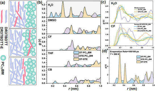 FIGURE 1
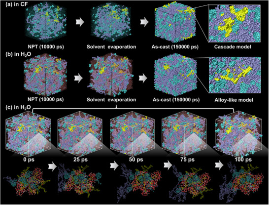 FIGURE 2
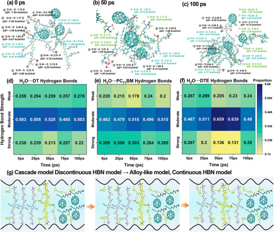 FIGURE 3
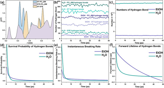 FIGURE 4
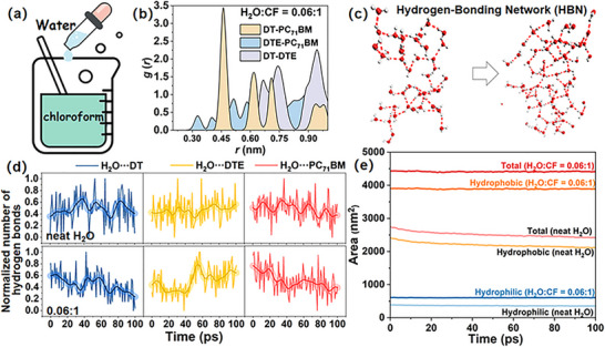 FIGURE 5
- —National Natural Science Foundation of China10.13039/501100001809
- —Jilin Province Development and Reform Commission10.13039/100015800
- —Jilin Provincial Scientific and Technological Development Program10.13039/501100013061
- —Jilin Provincial Education Department Scientific Research Program
- —Yanbian University Natural Science PhD Start‐up Fund
- —China Scholarship Council (CSC)
Peer Reviews
No public reviews on file for this paper yet. If you reviewed it on a platform where reviews are public (OpenReview, ICLR, NeurIPS, ICML), you can paste yours below so the community can read it here.
Videos
No videos yet. Explain this paper in a talk, walkthrough, or lecture? Add one.
Taxonomy
TopicsOrganic Electronics and Photovoltaics · Machine Learning in Materials Science · Perovskite Materials and Applications
Introduction
1
Morphology fundamentally governs the performance of advanced functional materials [1, 2, 3], spanning from nanoscale packing to mesoscale organization and thereby controlling excited‐state dynamics [4], carrier transport [5], and mechanical stability [6] across diverse systems [7, 8, 9]. In particular, organic solar cells (OSCs) are highly sensitive [10], since the power conversion efficiency (PCE) and stability depend on the optimal balance between phase separation and molecular ordering within the active layer [11, 12, 13]. Although morphology optimization through substitution [14, 15, 16], solvent engineering [17], and multicomponent strategies [18, 19] have enabled PCEs above 20% [20, 21, 22], current morphology design is guided more by empirical rules than by first principles, which limits the transferability and reproducibility of these strategies. Therefore, the urgent demand for a broadly applicable strategy to achieve rational control of morphology evolution becomes evident.
Intermolecular interactions provide a physically grounded route toward predictive control [23, 24]. Among them, hydrogen bonding offers directional and reversible forces that regulate molecular stacking and phase separation during solution processing [25, 26, 27]. Previous studies have demonstrated that deliberately introduced hydrogen‐bonding motifs can improve morphology stability and mechanical robustness in OSC blends [21, 22], highlighting the potential of hydrogen bonding as a multifunctional regulator of efficiency and durability [21]. Nevertheless, most of these approaches rely on specific molecular designs or dedicated additives, which limit their general applicability and complicate material synthesis.
Here, we propose a counterintuitive strategy in which trace amounts of water (H_2_O), traditionally regarded as an unwanted impurity, are repurposed as functional additives to regulate morphology evolution through dynamic hydrogen‐bonding networks (HBNs). During solvent evaporation [28], H_2_O molecules interact with carbonyl and fluorine motifs to initiate HBN formation, which serves as a molecular‐level switch guiding the blend toward distinct morphological arrangements and enabling controllable morphology engineering. Our molecular dynamics (MD) simulations [29] establish the mechanistic basis of this process and align with experimental observations [21]. By redefining the role of H_2_O from an unwanted impurity to a morphology‐regulating agent, this work establishes HBN engineering as a broadly applicable framework for active‐layer design, with implications for supramolecular assemblies [30, 31], environmentally benign processing [32, 33], and functional materials where weak interactions dictate performance [34].
Results and Discussion
2
Solvent‐Directed Control of the Guest Distribution
2.1
The solvent environment governs the distribution of the guest component during ternary film formation. We selected representative solvents along a polarity gradient and performed MD simulations on DR3TBDTT (DT):DR3TBDTT‐E (DTE):PC_71_BM, owing to its tunable cascade (Figure 1a, bottom) and alloy‐like morphologies (Figure 1a, top) [35, 36]. Solvent effects were examined through center‐of‐mass (COM) radial distribution function (RDF) analysis in systems processed with H_2_O, dimethyl sulfoxide (DMSO), chloroform (CF), tetrahydrofuran (THF), and chlorobenzene (CB). Further computational details are provided in Sections S1 and S2. As shown in Figure 1b, only the H_2_O‐processed system deviates from the typical ordering of the first nearest neighbor peak (r DT‐PC71BM < r DTE‐PC71BM < r DT‐DTE). In H_2_O, the order is inverted, with DTE showing stronger spatial correlation with DT than with PC_71_BM, indicative of an alloy‐like morphology, whereas other solvents favor cascade arrangements. The comparisons of binary and ternary blends (Figure 1c) confirm the deviation. The ternary RDFs of DT and DTE lie between their respective binaries in CF, while in H_2_O, they nearly overlap, indicating full embedding of DTE within the DT domain. Changing the H_2_O evaporation temperature from 300 to 280 K or 320 K reverses the RDF ranking (Figure S3), evidencing a temperature‐dependent shift in thermodynamic preference. In contrast, reducing the H_2_O evaporation rate at 300 K preserves the baseline ranking (Figure 1d), indicating that temperature shifts the thermodynamic preference of local packing within the explored range, whereas moderate changes in evaporation rate do not alter the distance ordering.
(a) Schematic illustration of DR3TBDTT‐E (DTE) spatial distributions in the ternary DT:DTE:PC71BM blends, including locations within the DR3TBDTT (DT) domains, within PC71BM domains, and at the DT and PC71BM interface. (b) COM RDFs of DT‐PC71BM, DTE‐PC71BM, and DT‐DTE in different solvents, DT‐PC71BM, DTE‐PC71BM represent the centroid distances between the PC71BM C70 unit and the BDT units originating from DT and from DTE, respectively. (c) COM RDFs of binary systems (DT:PC71BM and DTE:PC71BM) and ternary DT:DTE:PC71BM, DT withDTE‐PC71BM represent the center of mass distances between C70 and the BDT units originating from the DT‐DTE mixed environment. (d) RDFs of the ternary system with H2O evaporation (100 molecules/100 ps). Computational details and fragment definitions are provided in Sections S1 and S2.
Time‐Resolved Morphological Evolution
2.2
Solvent choice dictates the morphological endpoint. To uncover the underlying dynamic transition process and the unique role of H_2_O, we further tracked the time‐resolved morphological evolution at the atomic level. Understanding the transformation from cascade to alloy‐like morphology requires direct insight into dynamic molecular rearrangement. The time‐resolved RDF analysis to track changes in the COM distance ordering for DT:DTE:PC_71_BM in H_2_O and CF solvents is shown in Figure 2. In CF, solvent evaporation produces a traditional morphology arrangement (Figure 2a), while in H_2_O, an alloy‐like morphology emerges (Figure 2b). RDF analyses capture the switch in distance ordering within the first 100 ps (Figure S6), consistent with the transformation observed in Figure 2a,b.
Morphological evolution of DT:DTE:PC71BM blends during the simulation process. Solvent evaporation produces a cascade‐type morphology in CF (a) and an alloy‐like model in H2O (b). (c) Time‐resolved snapshots during 100 ps in H2O reveal progressive solvent evaporation and hydrogen‐bonding network formation. Iceblue corresponds to DT, cyan to PC71BM, and yellow to DTE, while red dashed lines mark hydrogen bonds between H2O molecules.
Beyond static RDF profiles, we aimed to comprehend the molecular basis of DTE migration and domain embedding. To quantify the migration of DTE into DT domains, mean square displacement (MSD) was calculated for individual DTE molecules over 0–100 ps (Figure S7). DTE‐centered clusters were defined using a cut‐off of 0.56 nm, derived from the first RDF peak relative to neighboring DT and PC_71_BM, and representative clusters in H_2_O were selected to trace directional motion and local contacts (Section S3.2). DTE contains ester‐functionalized BDT units that engage in hydrogen bonding with H_2_O, which biases its migration and embedding behavior compared with DT.
The time‐resolved snapshots in H_2_O (Figure 2c) delineate a temporal pathway of the transition. At 0 ps, the ternary blend exhibits a cascade model, where PC_71_BM partially disrupts the hydrogen bonding of H_2_O, resulting in fragmented and discontinuous HBNs. During 25–75 ps, redistribution of the components increases mixing and strengthens hydrogen bonding. The DTE clusters become increasingly encapsulated by interconnected O─H···O motifs, reflecting the development of continuous HBNs. At 100 ps, the cage‐like HBN consolidates and preferentially embeds DTE in DT‐rich regions, while separating it from PC_71_BM to establish alloy‐like uniformity. This evolution suggests that alloy‐like morphologies originate early and are stabilized not only by packing geometry but also by the maintenance of HBN continuity.
Mechanistic Origin: Formation of Continuous HBNs
2.3
To further investigate the microscopic mechanism for alloy‐like stabilization, we analyzed the local hydrogen‐bonding configurations and the evolution of bond strength within DTE‐containing regions. Energy partitioning based on Atoms in Molecules (AIM) analysis identifies strong, moderate, and weak hydrogen bonds, which are used to quantify the emergence of network continuity (Section S3.3). Representative clusters extracted from 0, 50, and 100 ps reveal the progression of local hydrogen‐bonding environments. At 0 ps in Figure 3a, the interactions between H_2_O and DTE are primarily weak to moderate due to disruption from PC_71_BM, forming fragmented and discontinuous HBNs. By 50 ps in Figure 3b, the number of strong hydrogen bonds decreases, indicating a transient destabilization of the network despite partial reorganization of H_2_O molecules. At 100 ps in Figure 3c, strong O‐H···O interactions reappear, and H_2_O molecules on the DTE surface form a cage‐like configuration, contributing to the reestablishment of a continuous HBN. The transient disruption reflects the highly dynamic yet resilient nature of HBNs. Additional weak and moderate bonds form between H_2_O and DT via carbonyl oxygen and sulfur atoms, driving DTE into the DT phase. Within this confined network, intermolecular hydrogen bonds among interior H_2_O molecules interact only weakly with external components. This behavior reflects the formation of a spatial boundary that structurally segregates DTE from PC_71_BM. This encapsulation stabilizes the alloy‐like morphology by physically isolating DTE within the DT phase.
Hydrogen‐bond strength and network evolution during the solvent‐driven transition. (a‐c) Representative DTE‐centered clusters at 0, 50, and 100 ps with annotated O‐H···O distances and hydrogen‐bond energies to neighboring fragments. (d‐f) Heat maps showing the time evolution of hydrogen‐bond strength distributions for H2O···DT, H2O···PC71BM, and H2O···DTE hydrogen bonds; color denotes the normalized proportion within each strength range. (g) Schematic pathway from a fragmented to a continuous HBNs that stabilizes the alloy‐like morphology. Details of energy thresholds are given in Section S3.3.
Heat maps of H_2_O interacting with the three components (Figure 3d–f) show distinct behaviors. The distribution and continuity of strong hydrogen bonds vary across time and components. At 0 ps, 27% of H_2_O···DTE hydrogen bonds are already classified as strong, suggesting that the alloy‐like morphology may exist as a metastable configuration even before macroscopic blending occurs. However, these strong interactions between H_2_O and DTE undergo a transient decline in strength from 50 to 75 ps, indicating a temporary disruption of the HBN. By 100 ps, strong bonds reappear, particularly in interactions involving both DTE and DT, which reflects a dynamic reorganization process that stabilizes the continuous HBN and thereby preserves the alloy‐like morphology. In contrast, H_2_O···DT hydrogen bonds remain largely persistent over time, while H_2_O···PC_71_BM hydrogen bonds are consistently weak, underscoring their limited contribution to network formation. A conceptual representation of this transformation mechanism is presented in Figure 3g, where the cooperative effects of network rigidity and fluidity are illustrated as key contributors to morphological stabilization.
Dual versus Single Hydrogen Bonds
2.4
To distinguish the specific contribution of the dual hydrogen‐bonding ability of H_2_O from generic single‐donor solvent effects, ethanol (EtOH), containing only one hydrogen‐bond donor site, was used as a comparative solvent. As shown in Figure 4a and Section S4, EtOH fails to induce alloy‐like morphology, owing to the dispersed nature of its hydrogen‐bonding interactions. H_2_O forms many more hydrogen bonds with each component than ethanol (Figure 4b), and self‐hydrogen bonding in H_2_O far exceeds that in EtOH (Figure 4c), giving a denser network. This advantage is not only quantitative. Each H_2_O molecule provides two donating hydrogens and two lone pairs that act as hydrogen‐bonding acceptor sites, enabling multi‐directional and network spanning connectivity. But ethanol with a single hydroxyl mainly forms terminal contacts that limit propagation. As shown in Figure 4d–f, hydrogen bonds in H_2_O exhibit faster decay, sharper early‐time dissociation behavior, and shorter forward lifetimes compared to EtOH. These features indicate that individual hydrogen bonds in H_2_O are highly dynamic yet continuously reformed, yielding a flexible and reconfigurable HBN. Conversely, EtOH forms more static hydrogen bonds with limited mobility, failing to support network‐level rearrangement.
Comparative analysis of hydrogen‐bonding behavior between H2O and EtOH. (a) COM RDF maps in EtOH solvents. (b) Number of hydrogen bonds formed between H2O or EtOH and other blend components. (c) Total number of self‐hydrogen bonds among H2O or EtOH molecules. (d) Survival probability of hydrogen bonds over time. (e) Instantaneous breaking rate (ps−1) of hydrogen bonds, where H2O exhibits an earlier and sharper dissociation peak. (f) Forward lifetime (ps) of hydrogen bonds. H2O shows transient and regenerating hydrogen bonds, forming a dynamic HBN, while EtOH lacks such connectivity.
Generality Across Non‐Fullerene Ternary Blends
2.5
To assess generality, we examined three representative non‐fullerene ternary blends, PM6:L8‐BO:Y‐SeNF [37], PM6:Y6:LA1 [38], and PM6:BTR:Y6 [39] (Figures S1b–d and S4), which could encompass a range of chemical structures and molecular interactions, enabling a broad validation of the proposed HBN mechanism. COM RDFs in all cases (Figure S9) show the alloy‐like distance order in H_2_O, which suggests that the formation of alloy‐like morphology is not an isolated phenomenon. HBNs (Figure S10) can emerge in diverse donor‐acceptor frameworks under suitable solvent conditions. Specifically, time‐resolved analysis of PM6:L8‐BO:Y‐SeNF reveals a transition from cascade to alloy‐like morphology (Figure S11a) with directed motion of Y‐SeNF from PM6‐rich regions toward L8‐BO (Figure S11b). Concurrently, the number of PM6 and L8‐BO molecules surrounding Y‐SeNF was counted at 0 and 100 ps (Figure S11c), showing an increasing presence of L8‐BO in the local environment. Comparable trajectories are observed for PM6:Y6:LA1 and PM6:BTR:Y6 (Figure S11d–i). These observations confirm that the HBN‐driven mechanism is not limited to fullerene systems but is general to modern non‐fullerene ternary blends, which support the generality of the HBN mechanism.
A Practical Co‐Solvent Strategy and Threshold
2.6
A Threshold Window in H2O:CF Environment
2.6.1
To translate the H_2_O‐driven mechanism into a practical processing route, we explored a co‐solvent condition (Figure 5a; Section 2.5) that preserves the hydrogen‐bonding benefit of H_2_O while maintaining solubility and volatility suitable for OSC fabrication. We mapped H_2_O:CF from 4:1, 1.50:1, 0.90:1, 0.67:1, 0.34:1, 0.25:1, and 0.15:1 to 0.06:1 (Figure 5b; Section S6.1). Reading from high to low H_2_O fraction, the COM RDF order follows a consistent progression. The ternary system at 4:1, 1.50:1, 0.90:1, and 0.67:1 passes through an alloy‐like window and then relaxes to a cascade outcome (Figure S14), while at 0.34:1, 0.25:1, and 0.15:1 the order remains CF‐like throughout, indicating a cascade morphology. At 0.06:1, the order coincides with that in H_2_O and remains alloy‐like at equilibrium (Figure 5c). This sequence indicates a gradual loss of hydrogen‐bonding continuity as the H_2_O fraction decreases, with a low fraction threshold near 0.06:1 where targeted HBNs are still sufficient to stabilize alloy‐like alignment. Similar to the H_2_O solvent, the continuous HBNs form in the 0.06:1 solvent ratio and drive DTE migration (Figure S15). It promotes the migration of DTE to the DT phase while reducing the contact with PC_71_BM. At 0.06:1, the continuous HBN forms persistent hydrogen bonds with DTE, resulting in limited migration over 0–100 ps (Figure S16). It indicates that HBN encapsulation hinders the migration of DTE. The bonding energy between the continuous HBNs and PC_71_BM is reduced, which leads PC_71_BM away from DTE.
(a) Schematic illustration of the co‐solvent design strategy. (b) COM RDF progression as a function of H2O:CF = 0.06:1. (c) A HBN at the 0.06:1. (d) Temporal statistics of the total number of hydrogen bonds between H2O and each component under (top) neat H2O, and (bottom) H2O:CF = 0.06:1. (e) Solvent‐accessible surface area of a solute in the critical process from the cascade model to the alloy‐like model during MD simulations with neat and 0.06:1 solvent ratios. Total Solvent‐accessible surface area = hydrophobic surface area + hydrophilic surface area.
Figure 5d compares hydrogen bond counts and shows that DTE with H_2_O and total network bonding are strongly enhanced relative to CF‐like conditions (Section S6.1.3). Figure 5e shows a higher solvent‐accessible surface area (SASA, Section S6.1.4) in CF with trace H_2_O than in neat H_2_O. This indicates that co‐solvents promote more extended and exposed conformations rather than compact ones. Hydrophobic segments remain compatible with CF, and polar sites reorient to recruit scarce H_2_O and form specific hydrogen bonds. Together, these observations support a practical co‐solvent window: a small H_2_O fraction near 0.06:1 seeds a transient, network‐spanning HBN early in drying, after which H_2_O is removed while the alloy‐like alignment persists. Such a co‐solvent window offers a realistic route to integrate H_2_O‐mediated morphology control into the OSC processing.
Solvent‐Dependent Activation Windows of the Co‐Solvent Strategy
2.6.2
To clarify the effectiveness and robustness of the co‐solvent strategy, we performed a systematic scan of H_2_O fractions in another three representative H_2_O mixed solvent systems, namely H_2_O:CB, H_2_O:DMSO, and H_2_O:THF (Figures S17–S19), arranged in the order of solvent polarity shown in Figure 1. The cross‐solvent comparison indicates that HBNs induced alloy‐like models can be accessed across all examined systems, although the required compositions differ markedly (Section S6.2.2). These variations are consistent with the expected influences of H_2_O miscibility, intrinsic solvent polarity, and the competitive balance of hydrogen bonding between H_2_O and solvent.
In CF, the extremely low miscibility with H_2_O leads to localized HBNs that interact strongly with nearby donor and acceptor molecules, allowing trace H_2_O at 0.06:1 to stabilize an alloy‐like configuration. CB presents an intermediate activation regime, where only moderate H_2_O fractions offer sufficient association between H_2_O and solutes without inducing macroscopic segregation. In DMSO, strong solvent‐H_2_O hydrogen bonding keeps H_2_O highly dispersed at moderate or high H_2_O content, which suppresses the formation of interfacial H_2_O‐solute hydrogen bonds. Alloy‐like morphology appears only at very low H_2_O fractions such as 0.15:1 and 0.06:1, where isolated H_2_O molecules are sufficiently unsolvated to engage in targeted interfacial hydrogen bonding and initiate HBN formation. THF exhibits the opposite dependence. Since THF is highly miscible with H_2_O, hydrogen‐bonding motifs are dispersed at low H_2_O levels, and only H_2_O‐rich conditions restore the connectivity needed to activate the HBN mechanism (Section S6.2.3).
Overall, the HBN mechanism operates across a broad solvent spectrum, whereas the activation window is governed by solvent polarity, H_2_O miscibility, and the hierarchical competition among hydrogen‐bonding interactions. Such a solvent‐dependent activation landscape provides a practical design space in which trace H_2_O fractions act as effective morphological additives without compromising solution processability.
Conclusion
3
In conclusion, our study establishes H_2_O as a functional additive that transforms from an impurity into a key regulator of morphology in ternary OSCs. Rather than being dictated by solvent evaporation kinetics, morphology evolution is shown to be governed by the thermodynamic continuity of HBNs. This insight clarifies the distinct role of H_2_O relative to other protic solvents and highlights HBN engineering as a broadly applicable principle. Systematic mapping further reveals a threshold regime where even trace amounts of H_2_O can seed network continuity and lock in stable morphology, which offers a practical handle for rational processing strategies in ternary OSCs.
Methods
4
All the all‐atom MD simulations were performed using the GROMACS 2018 software package [40]. The atom types and intermolecular interaction parameters for all molecules were derived from the general amber force field (GAFF) [41] using the restrained electrostatic potential (RESP) fitting method. Under the NPT ensemble, a leap‐frog integrator [42] with a time step of 1 fs and 3D periodic boundary conditions was employed. A spherical cut‐off of 1.2 nm was used for the summation of van der Waals (vdW) interactions, and the particle‐mesh Ewald (PME) [43] solver was employed for long‐range Coulomb interactions. Molecular structures and detailed definitions are provided in the Sections S1 and S2. Hydrogen bond energies were obtained from quantum chemical calculations with Gaussian 16 [44] and analyzed with Multiwfn 3.8 (dev) [45, 46, 47] in Section S3.3, which underpins the continuity analysis in Section 2.3. For clarity, all abbreviations used in this work are listed with their full names or definitions in the Appendix of the Supporting Information.
Conflicts of Interest
The authors declare no conflicts of interest.
Supporting information
Supporting File: advs73561‐sup‐0001‐SuppMat.docx.
The reference list from the paper itself. Each links out to its DOI / PubMed record.
- 1F. Hu , G. Yang , L.‐M. Zheng , G.‐J. Liang , and Q.‐M. Wang , “Deciphering Icosahedra Structural Evolution with Atomically Precise Silver Nanoclusters,” Science 389, no. 6763 (2025): 921–924, 10.1126/science.adx 6639.40875839 · doi ↗ · pubmed ↗
- 2R. Zhang , H. Chen , T. Wang , et al., “Equally High Efficiencies of Organic Solar Cells Processed from Different Solvents Reveal Key Factors for Morphology Control,” Nature Energy 10, no. 1 (2025): 124–134, 10.1038/s 41560-024-01678-5. · doi ↗
- 3J. E. Paul , Y. Gao , Y. K. Go , et al., “Controlled Patterning of Crystalline Domains by Frontal Polymerization,” Nature 634, no. 8032 (2024): 85–90, 10.1038/s 41586-024-07951-7.39294384 · doi ↗ · pubmed ↗
- 4S. Giannini , W.‐T. Peng , L. Cupellini , D. Padula , A. Carof , and J. Blumberger , “Exciton Transport in Molecular Organic Semiconductors Boosted by Transient Quantum Delocalization,” Nature Communications 13, no. 1 (2022): 2755, 10.1038/s 41467-022-30308-5.PMC 912008835589694 · doi ↗ · pubmed ↗
- 5G. Cai , Z. Chen , X. Xia , et al., “Pushing the Efficiency of High Open‐Circuit Voltage Binary Organic Solar Cells by Vertical Morphology Tuning,” Advanced Science 9, no. 14 (2022): 2200578, 10.1002/advs.202200578.35315238 PMC 9108622 · doi ↗ · pubmed ↗
- 6S. E. Root , S. Savagatrup , A. D. Printz , D. Rodriquez , and D. J. Lipomi , “Mechanical Properties of Organic Semiconductors for Stretchable, Highly Flexible, and Mechanically Robust Electronics,” Chemical Reviews 117, no. 9 (2017): 6467–6499, 10.1021/acs.chemrev.7b 00003.28343389 · doi ↗ · pubmed ↗
- 7Z. Wang , D. Zhang , L. Yang , et al., “Mechanically Robust and Stretchable Organic Solar Cells Plasticized by Small‐Molecule Acceptors,” Science 387, no. 6732 (2025): 381–387, 10.1126/science.adp 9709.39847644 · doi ↗ · pubmed ↗
- 8X. Xu , Y. Li , and Q. Peng , “Ternary Blend Organic Solar Cells: Understanding the Morphology from Recent Progress,” Advanced Materials 34, no. 46 (2022): 2107476, 10.1002/adma.202107476.34796991 · doi ↗ · pubmed ↗