Mercator: A modular swarm-dedicated robot platform
Miquel Kegeleirs, David Garzón Ramos, Jeanne Szpirer, Cristobal Lara Vera, Guillermo Legarda Herranz, Ilyes Gharbi, Gianpiero Francesca, Mauro Birattari

TL;DR
Mercator is a new, affordable robot platform designed for swarm robotics research, offering modern features like object recognition and communication.
Contribution
Introduces Mercator, a modular and low-cost robot platform specifically built for modern swarm robotics experimentation.
Findings
Mercator supports advanced perception, navigation, and communication for swarm robotics.
The platform has been used in peer-reviewed research and academic theses.
Mercator aligns laboratory swarm experiments with real-world robotic systems.
Abstract
Despite decades of research, swarm robotics still lacks realistic applications. A primary obstacle is the absence of modern, reliable, and affordable robot platforms for experimentation. Existing commercial robots are often outdated or too limited in sensing, computation, and communication. We introduce Mercator, a modular mobile robot purpose-built for contemporary swarm studies in both laboratory and indoor environments. Mercator integrates on-board object and people recognition, short- and long-range obstacle detection, ceiling-based tracking, and local, decentralized communication. By combining these capabilities in a low-cost and extensible package, Mercator enables swarm robotics research to align with modern mobile robotics standards, supporting navigation, mapping, and advanced perception in laboratory settings. This design promotes closer alignment between laboratory swarm…
Genes, proteins, chemicals, diseases, species, mutations and cell lines named across the full text — each resolved to its canonical identifier and authoritative record.
Click any figure to enlarge with its caption.
 Figure 1
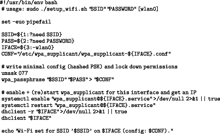 Figure 2
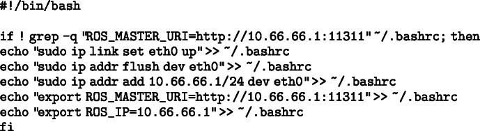 Figure 3
 Figure 4
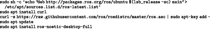 Figure 5
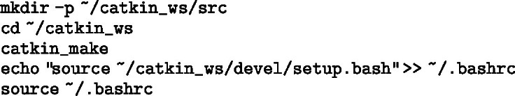 Figure 6
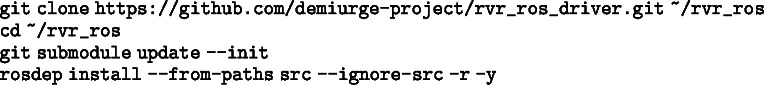 Figure 7
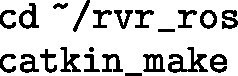 Figure 8
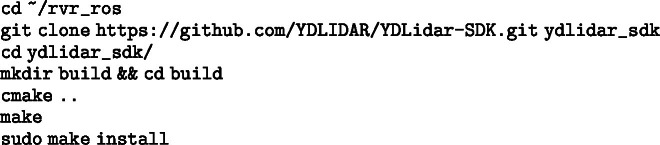 Figure 9
 Figure 10
 Figure 11
 Figure 12
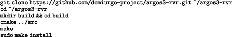 Figure 13
 Figure 14
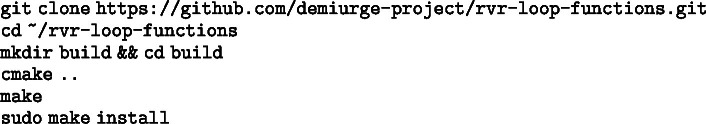 Figure 15
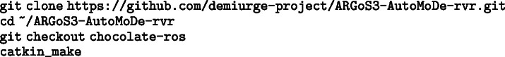 Figure 16
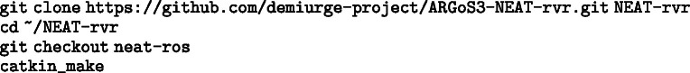 Figure 17
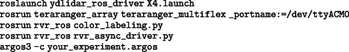 Figure 18
 Figure 19
 Figure 20
 Figure 21
 Figure 22
 Figure 23
 Figure 24
 Figure 25
 Figure 26
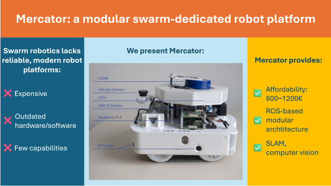 Figure 27
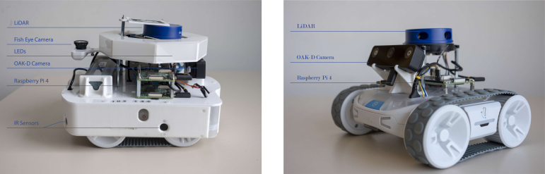 Figure 28
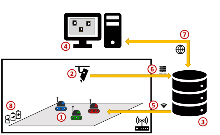 Figure 29
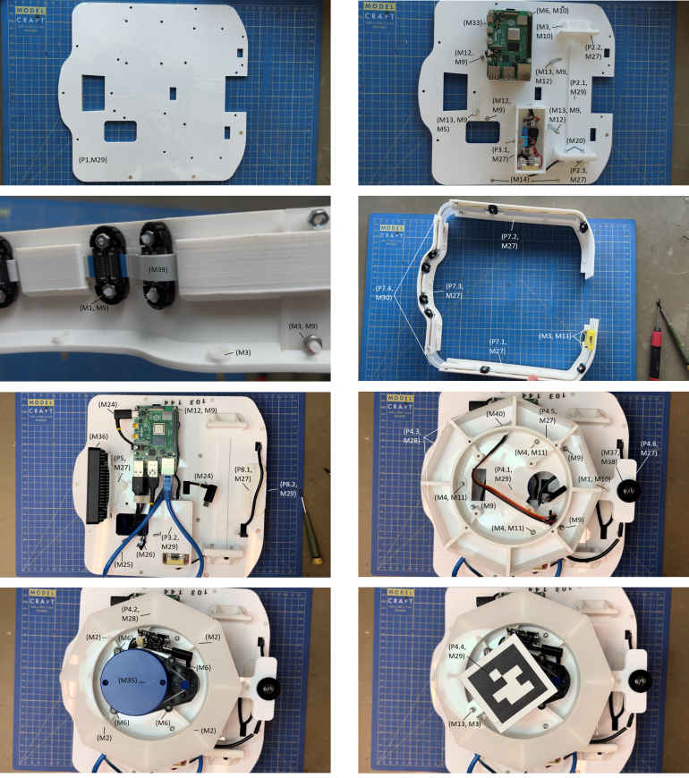 Figure 30
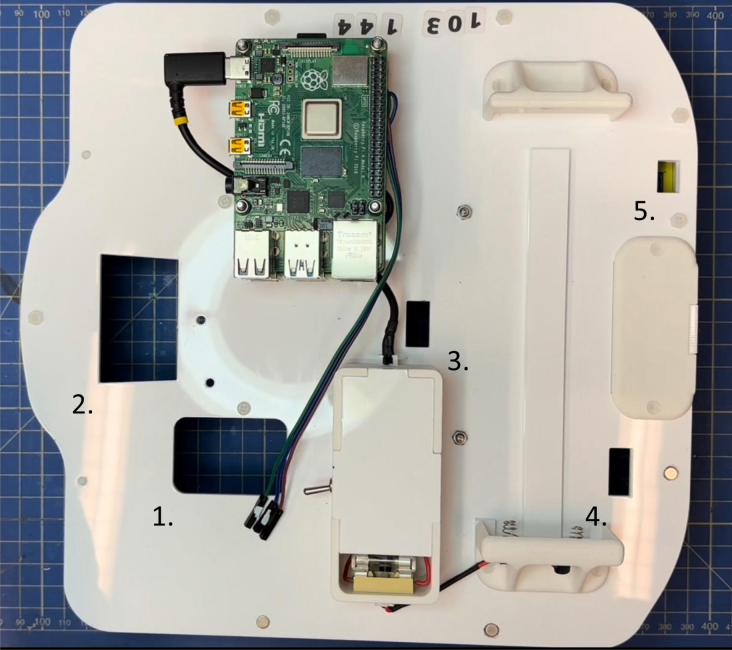 Figure 31
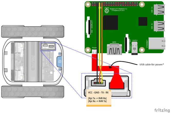 Figure 32
Peer Reviews
No public reviews on file for this paper yet. If you reviewed it on a platform where reviews are public (OpenReview, ICLR, NeurIPS, ICML), you can paste yours below so the community can read it here.
Videos
No videos yet. Explain this paper in a talk, walkthrough, or lecture? Add one.
Taxonomy
TopicsRobotics and Sensor-Based Localization · Social Robot Interaction and HRI · Robotic Locomotion and Control
Specifications table
Hardware nameMercatorSubject areaEngineering and material scienceHardware typeElectrical engineering and computer scienceClosest commercial analogTurtleBot 4Open source licenseCreative Commons Attribution 4.0 InternationalCost of hardware€1200Source file repositoryhttps://doi.org/10.5281/zenodo.17399308
Hardware in context
1
A major barrier to real world experimentation with robot swarms is the lack of modern, affordable, and reliable experimental robot platforms [1]. Experiments with physical robots remain expensive and time-consuming—challenges that scale with swarm size. Researchers also face logistical constraints: large experimental spaces are often unavailable or costly, and acquiring dozens or hundreds of robots to setup a robot swarm is financially prohibitive. Widely used platforms in single- or multi-robot research — such as AgileX Limo [2], Clearpath Husky [3], or TurtleBot 4 [4] — are typically too large and/or expensive to scale effectively for swarm robotics experiments. This has led to the development of swarm-specific platforms that prioritize low production cost and compactness, often at the expense of sensing, actuation, and processing capabilities.
Among these, the e-puck [5] and the Kilobot [6] are the most prominent, but both remain limited with respect to modern robotics research—manufactured with noisy sensors, unreliable actuators, and outdated hardware. As a result, researchers often rely on abstracted environments and simplified tasks [7] to work around hardware constraints. This sets a discrepancy between swarm robotics’ target use cases — e.g., search-and-rescue, space exploration, and environmental monitoring — and simplified experiments that still dominate much of the literature [1], [7]. Focusing research on limited robots such as the e-puck and the Kilobot prevents adopting the very capabilities that make modern field robotics possible—such as SLAM for enhanced navigation, vision-based perception for scene understanding, and people detection or re-identification for human-centric tasks [8].
In contemporary mobile robotics research, such capabilities are typically given for granted: robotic systems are expected to integrate onboard perception, state estimation, and navigation within standardized and modular software architectures [9]. In practice, these capabilities are also often tightly coupled within a software architecture supported by the Robot Operating System (ROS), which has become the de facto middleware for mobile robotics research and deployment. Compliance with ROS-based workflows enables reproducibility, modular development, and direct reuse of widely adopted software components, and is now a defining characteristic of modern mobile robotic platforms.
A few researchers have devoted effort to modernize legacy swarm robotics platforms. For example, the Pi-puck extension [10] boosts the e-puck’s processing power with a Raspberry Pi; the Xpuck achieves a similar upgrade using a Hardkernel Odroid XU4 [11]; and the ROS-compatible operating system DeimOS [12] provides modern software support without any hardware modifications. A similar upgrade is available for the Kilobot [13]. However, these solutions are still bound by the limitations of the original robot design.
The cost/capability ratio is equally critical. The Kilobot is inexpensive, but its sensing, actuation, and processing are extremely limited. More problematic is the e-puck: even though its hardware is outdated, its base price is rather high, and it climbs further when commonly required add-ons — such as the Omnivision Module extension — are included. See Table 1 for costs.
To overcome the combined hurdles of cost, scalability, and outdated sensing/compute in existing swarm platforms, we introduce Mercator—a low-cost, ROS-driven robotic platform specifically designed for advanced swarm robotics experiments. Mercator combines compactness, extensibility, and affordability with modern sensing and computation capabilities. Its main features include:
- •A varied suite of sensors and processing modules for SLAM, computer vision, and environment interaction.
- •Full compatibility with both ROS1 and ROS2.
- •A compact, robust form factor suitable for indoor and urban environments.
- •Support for modern mobile robotics research, such as people detection, re-identification, and collaborative navigation.
The platform is available in two configurations (see Fig. 1):Fig. 1. Mercator (left) and Mercator-Lite (right) with their main components.Fig. 1
- •Mercator (Standard): A fully-equipped version with comprehensive sensing and onboard computing, ideal for vision-based tasks and SLAM.
- •Mercator-Lite (Lite): A reduced-cost version with essential sensors, optimized for large-scale swarm deployment and basic swarm behavior testing.
Table 1 compares the two Mercator variants with several commercially available swarm robotics platforms commonly used in research and education. To ensure a fair and focused comparison, we limit our analysis to commercially available platforms widely adopted in swarm research. The comparison focuses on key features relevant to open-source development, modularity, and accessibility. Table 1 details ROS compatibility, ease of customization, availability of design files and code, and relative cost, as follows:Table 1. Comparison of Mercator platforms with common swarm robotics platforms.Table 1. PlatformROSCustomizableOpen SourceCost (EUR)Max SpeedRun TimeSize (L×W×H)MercatorYes (ROS1/2)YesYes 12001 m/s 2 h250 × 260 × 200 mmMercator-LiteYes (ROS1/2)YesYes 8501 m/s 4 h185 × 216 × 70 mme-puck [5]Via Pi-PuckLimitedPartial 1500+*0.15 m/s 1 h70 × 70 × 50 mmKilobot [6]NoNoPartial 1000.01 m/s 3 h33 × 33 × 30 mmTurtleBot3 BurgerYes (ROS1/2)YesYes 8000.22 m/s 2 h 30138 × 178 × 191 mmTurtleBot3 Waffle PiYes (ROS1/2)YesYes 2000+0.26 m/s 2 h281 × 306 × 141 mmTurtleBot4Yes (ROS2)YesPartial 30000.31 m/s 3 h341 × 339 × 351 mmKhepera IV [14]PartialLimitedNo 3000+0.9 m/s 2 h135 × 135 × 70 mmThymio II [15]NoLimitedYes 2000.14 m/s 3 h110 × 112 × 53 mm The indicated price comprises the base e-puck robot and the Pi-puck extension.
- •ROS: Indicates whether the platform is natively compatible with the Robot Operating System.
- •Customizable: Denotes the ease with which the robot can be reconfigured or extended.
- •Open source: Refers to the availability and maintenance of both hardware (e.g., schematics, 3D models) and software (e.g., ROS packages), enabling replication without direct contact with the developers.
- •Cost: Provides a rough estimate of affordability, crucial for scaling to large swarm sizes.
As shown in Table 1, most swarm robotics platforms are not (fully) open-source and lack native ROS compatibility. They also tend to fall into two categories: (i) expensive robots with limited capabilities due to outdated hardware (e.g., e-puck and Khepera IV), or (ii) affordable robots that are severely limited in functionality (e.g., Kilobot and Thymio II). The TurtleBot family represents the closest commercially available alternative to Mercator. However, it is primarily designed as a general-purpose robotics platform solely focused on mobile robotics. As such, TurtleBots lack native support for robot-to-robot communication and perception, which are fundamental requirements for swarm robotics research. In contrast, Mercator is explicitly designed to support swarm interactions, natively integrating interaction mechanisms well established in the swarm robotics literature — such as color-based signaling for local communication and perception [16] — without requiring additional hardware or substantial platform modification. Custom-built robots — such as Swarmanoid Project’s Footbot [17], Colias [18], and Mona [19] — while valuable for specific tasks, are often designed for narrow applications, lack standardization, and are difficult to reproduce [20]. Even when schematics and assembly instructions are published, duplicating a custom design at scale is often time-intensive and requires advanced technical skills. In contrast, Mercator was designed to bridge this gap by providing a platform that combines the affordability and scalability of simple robots with the sensing, computation, and ROS compatibility of more advanced systems—while remaining easy to assemble using off-the-shelf components and minimal technical expertise, unlike most custom-built alternatives. Its design emphasizes accessibility, low cost, and functional density, enabling researchers to build scalable swarms with advanced capabilities using readily available hardware and open-source software.
Hardware description
2
The Mercator platform extends the capabilities of the Sphero RVR+ robot,2 a commercially available robot originally designed for educational purposes. Mercator retains the RVR+’s native features — such as differential tracked drive, odometry, an IMU, and a ground color sensor — and further integrates additional computation and sensing modules to enable advanced swarm robotics experiments.
Mercator (standard)
2.1
The standard Mercator configuration is engineered for computationally intensive tasks and enhanced perception. It features:
- •Processing: Dual Raspberry Pi 4 Model B units.
- •Architecture: The primary Raspberry Pi, powered by the RVR+’s internal battery, handles low-level control and runs a ROS driver (i.e., a ROS software stack to communicate with the RVR+ low-level microcontroller). The primary Raspberry Pi interfaces with a rotating LiDAR and eight IR proximity sensors. The secondary Raspberry Pi, powered by an additional RVR battery, is dedicated to vision processing using an OAK-D spatial camera and an upward-facing fisheye camera. This secondary Raspberry Pi also manages a set of RGB LED indicators.
- •Sensing and Actuation:
- –2D rotating LiDAR (YDLIDAR X4) with a 360-degree field of view, used for real-time obstacle detection and mapping.
- –OAK-D W stereo vision camera with onboard AI inference. It provides depth estimation and object recognition capabilities and serves as the robot’s primary visual perception module.
- –Upward-facing fisheye camera (standard Raspberry Pi camera fitted with a wide-angle fisheye lens) for ceiling-based localization.
- –8 × IR proximity sensors (TeraRanger Multiflex) distributed around the robot perimeter. They provide short-range obstacle detection and proximity awareness.
- –8 × individually addressable APA RGB LEDs used for robot identification, signaling, and debugging feedback during swarm tasks. All modules connect to the Raspberry Pis via USB or GPIO interfaces.
- •Software: Ubuntu 20.04 with support for both ROS1 and ROS2. This architecture enables rapid development, modular expansion, and integration with ROS-compatible components.
All components are mounted using lightweight, 3D-printed brackets and laser-cut acrylic. The entire system is designed for reproducibility, using only off-the-shelf parts. The assembly of Mercators is straightforward and typically takes under 3 h, with a total estimated cost of approximately €1200 per robot. Support for the UWB-based communication system is under development, with a dedicated space for the devices already integrated into the design.
Mercator-lite
2.2
The Mercator-Lite is a lightweight, cost-effective variant optimized for large-scale swarm deployments. It includes:
- •A single Raspberry Pi 4.
- •A rotating LiDAR (YDLIDAR X4) and an OAK-D W camera.
Despite being endowed with fewer hardware components, Mercator-Lite maintains full software compatibility with the standard Mercator. This enables Mercator and Mercator-Lite to be operated in mixed heterogeneous robot swarms. Unlike Mercator, Mercator-Lite can be built on earlier revisions of the Sphero RVR+ (e.g., RVR), as a means to reduce costing.3 Mercator-Lite can be assembled in under 1 h, with an estimated cost of approximately €850 per robot.
Software stack and modularity
2.3
Mercator software architecture is modular, ROS-native, and designed for extensibility. Both Raspberry Pis run Ubuntu 20.04 and support a wide array of robotics libraries. Each sensor and actuator is managed by dedicated ROS nodes, allowing easy customization and integration of additional hardware. In addition, ROS facilitates fusing readings from the LiDAR and depth camera, which is used for detecting other robots and estimating their relative pose (similarly to the range-and-bearing module of the e-puck).
The system adheres to standard ROS conventions, using publish–subscribe topics with standard message types. This approach facilitates debugging, modular reuse, and data logging. To address inconsistencies in the RVR+ color sensor — caused by overly fine-grained raw RGB outputs — a dedicated ROS node simplifies and stabilizes readings by mapping them to predefined color labels using a nearest-neighbor classifier.
Mercator supports both ROS1 (Noetic) and ROS2 (Foxy). ROS1 is used as the primary development environment due to its long-standing stability, extensive ecosystem, and mature support for widely adopted packages for SLAM, navigation, and sensor interfacing, which remain central to many experimental robotics workflows. Although ROS1 has formally reached end-of-life and Ubuntu 20.04 is approaching end-of-life, both continue to be widely used in research laboratories. Their adoption therefore represents a pragmatic choice that prioritizes experimental robustness, reproducibility, and compatibility with existing hardware and software stacks over early migration to newer but still evolving frameworks. Importantly, the system architecture is designed to remain forward-compatible with ROS2. Core components are modular and abstracted from middleware-specific implementations, enabling a gradual transition toward ROS2-based communication and more scalable multi-robot frameworks as these mature and become standard practice. Interoperability between ROS1 and ROS2 is also supported through established bridging mechanisms (e.g., the ros1_bridge package4), allowing mixed deployments and incremental migration.
Finally, it is important to note that the swarm experiments examples presented in this paper rely primarily on local, on-board perception and decentralized coordination—as this is a common setup in swarm robotics literature. The collective behavior of the swarm emerges solely from the local interaction that robots have with their peers and their environment. That is, the robots operate autonomously without centralized state estimation or structured inter-robot data exchange, and therefore do not directly benefit from the more advanced multi-robot system features introduced in ROS2 (i.e., multi-robot communication over topics). In this context, deploying a ROS1 architecture in each robot provides all required functionality without imposing additional architectural complexity. Yet, we are currently developing a ROS2 equivalent of the software that is available for Mercator in ROS1. Future work will leverage ROS2 middleware to support the exchange of more structured information between robots, enabling higher-level coordination mechanisms such as identity persistence and richer collective perception [21], [22].
Simulation compatibility
2.4
Mercator is fully integrated into the ARGoS3 simulation environment [23], featuring accurate modeling of actuators and sensors via the argos-rvr plugin. Sensor noise profiles are based on real-world measurements, supporting high-fidelity simulation-to-hardware transfer.
The platform is also compatible with AutoMoDe-RVR, a control software design framework tailored for Mercator that extends the family of methods AutoMoDe [24], [25]. AutoMoDe-RVR allows the optimization-based design of control software for Mercator via the design and simulation of probabilistic finite state machine (PFSM) controllers. Although ARGoS handles control natively without ROS, software developed in simulation can be transferred to physical Mercator units with minimal modification. Control software produced with AutoMoDe has been successfully ported from the e-puck to Mercator hardware with minimal adjustments [26]—showing transferability of standard swarm behaviors across platforms. We also provide support for frameworks to design control software for Mercator via neuroevolutionary robotics (NEAT [27], CMA-ES [28], and xNES [29]). See Table 3 (S1–S10) for details on the software components.
Key features
2.5
- •Modular and ROS-native: Customizable using sensor-specific ROS nodes.
- •Seamless simulation-to-hardware pipeline: Compatible with ARGoS3 and AutoMoDe.
- •Cost-effective: Comparable in cost to legacy platforms like the e-puck, with significantly enhanced capabilities.
- •Advanced functionality: SLAM, computer vision, ceiling localization, and people tracking.
- •Heterogeneous swarm support: Unified operation across standard and Lite models.
- •Accessible design: Assembled from off-the-shelf parts with 3D-printed and laser-cut mounts.
- •Detailed specifications: See Table 2 for a complete comparison of the two Mercator variants.
In summary, Mercator can support robotics research by:Table 2. Key specifications of Mercator and Mercator-Lite.Table 2. FeatureMercatorMercator-LiteBase platformSphero RVR+Sphero RVR or RVR+Processing units2×Raspberry Pi 4B1×Raspberry Pi 4BDevicesLiDAR, OAK-D W, fisheye, IR, LEDsLiDAR, OAK-D WSoftwareUbuntu 20.04 + ROS1/2Ubuntu 20.04 + ROS1/2Power supplyInternal + external batteryInternal batteryEstimated cost €1200 €850Size (L × W × H)250 × 260 × 200 mm185 × 216 × 70 mmWeight2.8 kg1.5 kgOpen source licenseCC BY 4.0CC BY 4.0RepositoryZenodoZenodo
- •Offering an affordable and reproducible platform for repeatable swarm experiments with modern sensing and standardized ROS-based software.
- •Enabling real-world validation of collaborative SLAM, swarm perception, and decentralized coordination algorithms.
- •Serving as a hands-on system for education and training in contemporary mobile robotics workflows.
- •Facilitating studies of human–robot interaction using onboard vision-based perception.
- •Bridging swarm robotics research with modern mobile robotics standards through transferability of algorithms across platforms.
Architecture of a swarm robotics experiment with a group of Mercators
2.6
A typical swarm experiment involving Mercators is structured as follows (see Fig. 2). A group of Mercators is deployed in an experimental environment (1), which may include obstacles, mission-related objects, or other robots. A wireless router provides network connectivity (5), allowing to deploy control software into the robots and receive experiment instructions — typically to initialize or start a run — from a experiments server (3), which acts as an operation and monitoring interface for the experimental infrastructure. The environment is monitored by an external tracking system (1) — for example, Tycho [30] — which estimates the state of each robot throughout the experiment. This information is streamed (6) to the server for logging, visualization, and post-experimental analysis. The tracking system does not communicate directly with the robots and does not influence their behavior during execution. Researchers interact with the system through a workstation (4), which provides access to the server, the tracking data, and experiment control tools either locally or for from the web (7). Finally, sufficient batteries and/or charging docks should be available (8) to enable rapid turnaround between experimental runs.Fig. 2. Typical architecture of a swarm robotics experiment with Mercators. The figure illustrates the (1) Mercators, (2) tracking system, (3) experiments server, (4) workstation, (5) wireless router, (6) experiment information streamed to the server, (7) access to experiments server, and (8) charging docks for Mercator.Fig. 2
Typically, the experimental workflow proceeds as follows. Required materials, such as robot control software and configuration files, are deployed to Mercators via secure shell (SSH). On each robot, a ROS master node is launched together with the RVR driver and the required sensing and actuation components (e.g., LiDAR, cameras, LEDs). Prior to each run, robots are positioned in the environment either manually or automatically using the tracking system—i.e., driving the robots to desired starting positions. The experiment is then initiated by starting the robots’ control software. During execution, Mercators operate fully autonomously, relying exclusively on onboard sensing, local computation, and decentralized interaction mechanisms. As noted in past sections, robot-to-robot coordination is currently achieved through local perception and signaling (e.g., by using the colors of Mercator’s LEDs module), rather than through centralized communication or shared global state. The tracking system provides real-time feedback to the researchers but does not participate in the control loop. It is used to track the motion of the robots and use this information to compute their performance in the task at hand. At the end of a run, robots are halted, batteries are replaced if necessary, and the procedure can be repeated for subsequent trials.
Design files summary
3
This section summarizes the mechanical, electronic, and software components required to replicate the Mercator platform. Unless otherwise noted, the descriptions and design files refer to the full Mercator configuration (Standard version). A separate subsection at the end covers the Mercator-Lite variant, which uses a reduced list of components.
Mercator design
3.1
The mechanical structure of Mercator is composed of modular elements mounted on the Sphero RVR+. Components are fabricated using a combination of laser-cut acrylic and 3D-printed PLA or PETG parts. The design emphasizes robustness and ease of assembly.
The structure includes (see Table 3 P1–P8 for corresponding files):
- •P1 – Base plate: A laser-cut platform that attaches securely to the top of the RVR+ and serves as the foundation for all other elements.
- •P2 – Battery rack: A combination of laser-cut (P2.1) and 3D-printed (P2.2-2.3) elements mounted at the rear of the robot for housing an external RVR battery, used to power the secondary Raspberry Pi and camera modules.
- •P3 – Fuse case: A 3D-printed case (P3.1) and laser-cut lid (P3.2) that protect the voltage DC-DC regulator and the fuse connected to the external battery.
- •P4 – Sensor tower: An elevated frame composed of laser-cut (P4.1-4.4) and 3D-printed parts (P4.5-4.6), mounted on four metal spacers, and designed to carry the rotating LiDAR and a RGB LED ring. A bracket positioned at the rear of the tower holds the upward-facing fisheye camera. In addition, a flat support for a QR tag identifier is positioned above the LIDAR with the help of spacers.
- •P5 – Camera mount: A front-facing, 3D-printed bracket that positions the OAK-D W camera at a fixed height and orientation to ensure consistent stereo vision and depth perception.
- •P6 – Camera mount (Lite): A front-facing, 3D-printed bracket for the Mercator-Lite that positions the OAK-D W camera at a fixed height and orientation to ensure consistent stereo vision and depth perception.
- •P7 – Sensor belt/bumper: A 3D-printed ring (P7.1-7.3) encircling the robot to mount eight IR proximity sensors. The front-left and front-right corners (P7.4) are laser cut in flexible material. It also acts as a protective bumper during collisions. A side segment of the belt, which covers access to the RVR+’s internal battery compartment, is magnetically attached to the platform to allow quick removal and battery replacement without tools.
- •P8 – UWB module bay: A 3D-printed case and laser-cut lid at the rear of the robot for optional integration of a UWB communication device.
The rest of Table 3 lists the main electronics (P9–P15) and software (S1–S10) components.Table 3. Mechanical design files (P1–P8), and main electronic (P9–P15) and software (S1–S10) components.Table 3. DesignatorDescriptionTypeOpen s. licenseFiles locationNotesP1Base plateDXFCC BY 4.0ZenodoP2Battery rackSTL + DXFCC BY 4.0Zenodo P2.1 Base rail DXF CC BY 4.0 P2.2 Support (button side) STL CC BY 4.0 P2.3 Support (connector side) STL CC BY 4.0P3Fuse caseSTL + DXFCC BY 4.0Zenodo P3.1 Case STL CC BY 4.0 P3.2 Lid DXF CC BY 4.0P4Sensor towerSTL + DXFCC BY 4.0Zenodo P4.1 Base plate DXF CC BY 4.0 P4.2 Cover DXF CC BY 4.0 P4.3 Side windows (8) DXF CC BY 4.0 P4.4 Tag support DXF CC BY 4.0 P4.5 LEDs support STL CC BY 4.0 P4.6 Fisheye camera support STL CC BY 4.0P5Camera mountSTLCC BY 4.0ZenodoP6Camera mount (Lite)STLCC BY 4.0ZenodoP7Bumper/Sensors beltSTLCC BY 4.0Zenodo P7.1 Right part STL CC BY 4.0 P7.2 Left part STL CC BY 4.0 P7.3 Front part STL CC BY 4.0 P7.4 Corners (2) DXF CC BY 4.0P8UWB module baySTL + DXFCC BY 4.0Zenodo P8.1 Case STL CC BY 4.0 P8.2 Lid DXF CC BY 4.0P9Raspberry Pi 4 (4GB)ElectronicsM33 in BoMP10YDLIDAR X4ElectronicsM35 in BoMP11OAK-D W stereo cameraElectronicsM36 in BoMP12LattePanda camera + fisheye lensElectronicsM37 and M38 in BoMP13TeraRanger Multiflex IR sensorsElectronicsM39 in BoMP14LED Strip APA 102ElectronicsM40 in BoMP15RVR official batteryElectronicsM32 in BoMS1ARGoS3-RVRGit repoMITGitHubPlugin for the ARGoS3 simulatorS2AutoMoDe-RVRGit repoMITGitHubAutoMoDe version for MercatorS3Reference modelGit repoMITGitHubReference model for AutoMoDeS4Loop functionsGit repoMITGitHubARGoS3 loop functions for AutoMoDeS5NEAT-RVRGit repoMITGitHubNEAT version for MercatorS6Pagmo-RVRGit repoMITGitHubC-MAS and xNES versions for MercatorS7Drivers and utilityGit repoMITGitHubROS nodes for the main driver and sensorsS8SD image (RPi primary)ImageCC BY 4.0ZenodoPre-built image for main control and LIDARS9SD image (RPi secondary)ImageCC BY 4.0ZenodoPre-built image for vision stack + camera nodesS10SD image (Lite)ImageCC BY 4.0ZenodoPre-built image for Mercator-Lite
Mercator-lite variant
3.2
Mercator-Lite reuses the same software and provides a reduced list of hardware components—see Table 4. Components are mounted directly on the RVR/RVR+ and a dedicated 3D-printed bracket (P6) is designed for the OAK-D camera.
Table 4. Summary of components and resources for the Mercator-Lite variant (refer to Table 3 for part descriptions).Table 4. DesignatorComponentNotesP9Raspberry Pi 4Main compute unitP10YDLIDAR X42D LiDAR for obstacle detectionP11OAK-D W CameraStereo vision and depth inferenceP6Camera mount (Lite)3D-printed bracket for OAK-DS10SD image (Lite)Pre-built image for Mercator-Lite
Bill of materials
4
Table 5 provides a summary of the bill of materials for the standard Mercator version. Table 6 provides a summary of the bill of materials for Mercator-Lite. Both bills of materials report only the cost of hardware components and do not account for labor costs (e.g., purchasing, fabrication, and assembly) or for access to equipment such as 3D printers, laser cutters, or soldering tools. These additional costs depend on local infrastructure and available resources and should therefore be estimated separately by the user.
Table 5. Comprehensive bill of materials (Mercator).Table 5. DesignatorNameQtyUnit cost (€)Total cost (€)Source of materialMaterial typeM1M3 8 mm Nylon Countersunk Bolts280.308.40https://befr.rs-online.com/web/PolymerM2M3 16 mm Nylon Countersunk Bolts90.353.15https://befr.rs-online.com/web/PolymerM3M3 12 mm Nylon Countersunk Bolts20.300.60https://befr.rs-online.com/web/PolymerM4M3 6 mm Stainless Steel Bolts20.090.18https://befr.rs-online.com/web/MetalM5M3 12 mm Stainless Steel Bolts130.111.10https://befr.rs-online.com/web/MetalM6M3 25 mm Stainless Steel Bolts30.150.45https://befr.rs-online.com/web/MetalM7M4 6 mm Stainless Steel Bolts20.130.26https://befr.rs-online.com/web/MetalM8M3 Washers80.080.64https://befr.rs-online.com/web/MetalM9M3 Stainless Steel Nuts440.093.96https://befr.rs-online.com/web/MetalM10M3 Nylon Nuts70.292.03https://befr.rs-online.com/web/PolymerM11M3 Locknuts250.102.50https://befr.rs-online.com/web/MetalM12M3 6 mm Brass Spacers40.481.92https://befr.rs-online.com/web/MetalM13M3 25 mm Stainless Steel Spacers120.435.16https://befr.rs-online.com/web/MetalM145 mm x 3 mm Neodymium Magnets 0.55 kg31.374.11https://befr.rs-online.com/web/CompositeM155 mm x 5 mm Neodymium Magnets 0.77 kg31.705.10https://befr.rs-online.com/web/CompositeM16Step Down Voltage DC-DC Regulator19.909.90https://whadda.com/SemiconductorM17Fusible Support10.450.45https://befr.rs-online.com/web/OtherM183A Fast Fusible10.440.44https://befr.rs-online.com/web/OtherM19Switch On/Off13.713.71https://befr.rs-online.com/web/OtherM20Springs for Battery Connections20.621.24https://befr.rs-online.com/web/MetalM21Female Connector Housing, 2 mm Pitch, 2 Way, 1 Row20.070.14https://befr.rs-online.com/web/PolymerM22Male Crimp Connector Housing, 2 mm Pitch, 2 Way, 1 Row20.180.36https://befr.rs-online.com/web/PolymerM23micro-USB to USB cable (RPi to LIDAR)11.451.45https://befr.rs-online.com/web/OtherM24Right-angle USB-C to USB cable (RPi to RVR)213.6727.34https://befr.rs-online.com/web/OtherM25Ethernet Cable (Raspberry to Raspberry)11.801.80https://befr.rs-online.com/web/OtherM26Jumpers Female-Female Connection (Raspberry to RVR and LEDs)70.221.54https://befr.rs-online.com/web/OtherM27PLA 3D printer filament1a29.3629.36https://befr.rs-online.com/web/PolymerM28PLEXIGLAS © LED, White WH14 GT, 3 mm1a29.7029.70https://www.plexiglas-shop.com/PolymerM29PLEXIGLAS © XT, White WN297 GT, 3 mm1a20.9020.90https://www.plexiglas-shop.com/PolymerM30Soft PVC strip 100 × 1.2 mm1a2.032.03https://www.superplastic.be/PolymerM31Sphero RVR+1349349https://www.eduwinkel.nl/OtherM32RVR Battery2b7070https://www.eduwinkel.nl/OtherM33Raspberry Pi 4B 8Go278.71157.42https://befr.rs-online.com/web/SemiconductorM34Micro SD card (at least 32GB)25.6811.32https://befr.rs-online.com/web/OtherM35YDLIDAR X4175.9075.90https://6eu.robotshop.com/SemiconductorM36OAK-D W Camera1331.55331.55https://www.mouser.be/SemiconductorM37Camera UVC 5MP USB LattePanda127.5027.50https://6eu.robotshop.com/SemiconductorM38Fisheye lens for mobile phone14.464.46https://www.amazon.com/OtherM39TeraRanger Multiflex 8 Sensor Kit146.9546.95https://eu.robotshop.com/SemiconductorM40LED Strip APA 102250.297.25https://opencircuit.shop/SemiconductoraRepresents one unit of the product; however, constructing a single Mercator does not require its full amount.bOne battery is provided with the Sphero RVR+, but Mercator requires an additional battery.Table 6. Comprehensive bill of materials (Mercator-Lite).Table 6. DesignatorNameQtyUnit cost (€)Total cost (€)Source of materialMaterial typeM5M3 12 mm Stainless Steel Bolts140.131.82https://befr.rs-online.com/web/MetalM8M3 Washers280.082.24https://befr.rs-online.com/web/MetalM9M3 Stainless Steel Nuts40.090.36https://befr.rs-online.com/web/MetalM11M3 Locknuts180.101.80https://befr.rs-online.com/web/MetalM12M3 6 mm Brass Spacers40.481.92https://befr.rs-online.com/web/MetalM13M3 25 mm Stainless Steel Spacers80.433.44https://befr.rs-online.com/web/MetalM23micro-USB to USB cable (RPi to LIDAR)11.451.45https://befr.rs-online.com/web/OtherM24Right-angle USB-C to USB cable (RPi to RVR)113.6713.67https://befr.rs-online.com/web/OtherM26Jumpers Female-Female Connection (Raspberry to RVR)30.220.66https://befr.rs-online.com/web/OtherM27PLA 3D printer filament1a29.3629.36https://befr.rs-online.com/web/PolymerM31Sphero RVR+1349349https://www.eduwinkel.nl/OtherM33Raspberry Pi 4B 8Go178.7178.71https://befr.rs-online.com/web/SemiconductorM34Micro SD card (at least 32GB)15.685.68https://befr.rs-online.com/web/OtherM35YDLIDAR X4175.9075.90https://6eu.robotshop.com/SemiconductorM36OAK-D W Camera1331.55331.55https://www.mouser.be/SemiconductoraRepresents one unit of the product; however, constructing a single Mercator-Lite does not require its full amount.
Build instructions
5
Once the materials described in Table 5 are available, the subsequent task is to produce the mechanical parts (see Table 3 P1–P8) and assemble the robot. The tools required for this process are a screwdriver, pliers, a 3D printer, and a laser cutter. A few steps require some soldering and wire stripping, but no specialized workshop equipment is strictly necessary. The assembly steps described below follow the Mercator construction demo videos,5 which serve as a visual guide throughout the process. In addition, Fig. 3 illustrates the main steps, with annotations identifying the relevant components.
Fig. 3. Main assembly steps annotated with materials.Fig. 3
Mechanical parts production
5.1
The pieces listed in Table 3 (P1–P8) must be produced by 3D printing and laser cutting. 3D-printed pieces include P2.2, P2.3, P3.1, P4.5, p4.6, P5, P7.1, P7.2, P7.3, and P8.1. They can be produced using regular PLA (M27). We selected white PLA so that the surface the bumper (P7) reflects rather than absorbs light, improving its detectability by the IR sensors on other Mercators. Laser-cut pieces include P1, P2.1, P3.2, P4.1, P4.2, P4.3, P4.4, P7.4, and P8.2. The cover and the windows of the sensor tower (P4.2 and P4.3) must be produced with semi-translucent material to ensure proper color diffusion (M28). The corners of the bumper (P7.4) must be produced with flexible material (M30). The other parts can be produced with white Plexiglas © (M29). We selected this material for its resilience and favorable aesthetic properties, but any other rigid material (e.g., MDF) can be used to reduce costs. Similarly, nylon bolts and nuts (M1, M2, M3, and M10) have been selected to match visually with Plexiglas © parts, but can be replaced by regular steel equivalents to reduce costs.
Mercator assembly
5.2
This section describes the installation of key structural and functional components on the base plate, including the sensor belt, power supply system, computing units, and mounting elements. These steps are carried out before attaching the base to the Sphero RVR+ and are essential for ensuring proper layout, accessibility, and cable organization. Most elements are first assembled and connected to the base plate, with the exception of the sensor tower (Sections 5.2.1, 5.2.3, and 5.2.2). All necessary cables are then properly routed and connected to the electronic devices (Section 5.2.5). The sensor tower is assembled and connected last to the plate (Section 5.2.4).
General assembly
5.2.1
The following steps describe how to assemble and attach the different elements to the laser-cut base plate (P1).
- 1.Battery rack (P2): Solder a short insulated hook-up wire to each of the two springs (M20). Position the springs in the dedicated space of one of the support (P2.3), pass the wires through the rear hole and fix the springs with glue. Attach a male crimp connector (M22) to the wires. Position the laser-cut rail (P2.1) and the 3D-printed battery supports (P2.2 and P2.3) to the rear section of the base plate and secure them using the matching screw holes (M2, M3, M11). P2.3 is positioned on the top of P2.1 and both are secured together. This will house the external RVR battery (P15).
- 2.Fuse case (P3): Assemble the fuse case (see Section 5.2.2 and position it adjacent to the battery mount. Secure it using the matching screw holes (M4, M11) on the base plate.
- 3.Sensor tower (assembly) (P4): Assemble the sensor tower (see Section 5.2.4 but do not attach to the base plate yet).
- 4.Camera mount (P5): Attach the OAK-D W camera (P11) to the 3D-printed mount (P5) using appropriate bolts (M7). Then, fix the mount to the front of the plate and install the camera in a stable forward-facing position. Secure it using the matching screw hole (M2, M11).
- 5.Bumper (P7): Insert neodymium magnets (M14) in the corresponding holes in the left part of the base plate and glue them. They should align with the magnets on the left part of the bumper. Assemble the bumper (see Section 5.2.3) and attach it with nylon nuts (M10) to the base plate using matching screw holes.
- 6.UWB module bay (P8): If UWB capabilities are required, secure the UWB modules inside the module bay (M6, M11) and attach the bay on the rear side of the base plate (M2, M11).
- 7.Raspberry Pi boards (P9): Mount both Raspberry Pi 4 boards on the right side of the base plate. The bottom one will serve as the primary control unit, the upper one for visual processing. First, secure the bottom one using bolts (M5) pointing upward. It is recommended to place nuts (M9) between the board and the plate to leave some space for pins and soldering protruding out of the bottom of the board. Then, attach spacers (M13) to the bolts and secure the upper Raspberry Pi with locknuts (M11).
- 8.Mounting screw preparation: Insert and loosely secure the bolts and spacers (M5, M12) that will later be used to attach the base plate and the sensor tower to the Sphero RVR+ mounting plate. These also serve as anchor points for organizing and guiding cables underneath the base, contributing to a clean and efficient cable layout.
- 9.Connections: Proceed with the setup of internal connections (see Section 5.2.5). It is easier to connect the sensor tower once it has been secured in the next step. Also, do not connect cables to the RVR+ yet.
- 10.Sensor tower (securing): Secure the sensor tower in the center of the plate with the bolts and spacers prepared at step 3 and connect the dedicated cables to the LEDs and LiDAR.
- 11.RVR+: Remove the mounting plate of the RVR+ and secure it to the base plate using bolts and spacers prepared at step 7, additional ones (M5, M12), and locknuts (M11). It is recommended to place washers (M8) between the RVR+ mounting plate and other elements to protect it from wear and tear. Once everything is tightly secured, connect the bottom Rasperry Pi to the RVR+ following instructions in Section 5.2.5.
Fuse case assembly
5.2.2
The fuse case protects the fuse and voltage regulator monitoring the additional battery used to power the upper Raspberry Pi. Its assembly is the sole part of the building process requiring a bit of soldering, with the exception of the connectors for the battery rack.
- 1.Prepare 6 short pieces of insulated hook-up wire.
- 2.Attach a wire to the right pin of a female connector (M21) and to the IN- pin of the voltage regulator (M16). Attach another wire to the left pin of the connector and to one of the pin of the fusible support (M17)
- 3.Attach a wire to the right pin of the on/off switch (M19) and to the other pin of the fusible support (M17). Attach another wire to the center pin of the switch and to the IN+ pin of the voltage regulator (M16).
- 4.Attach a wire to the right pin of the second female connector (M21) and to the OUT- pin of the voltage regulator (M16). Attach another wire to the left pin of the connector and to the OUT+ pin of the voltage regulator. The wires should be crossed.
- 5.Install the components into the 3D-printed fuse case (P3.1) and secure them:
- •Secure the fusible support to the top part of the case using a nylon bolt (M1).
- •Insert the connector wired to the fusible support in the hole right beneath it so that it is accessible from outside the fuse case, and glue it.
- •Similarly, insert the other connector in the opposite hole and glue it.
- •Detach the top nuts of the on/off switch to be able to pass the switch in the hole on the side of the case, then secure it again with the nuts.
- •Place the fusible (M18) in its support.
- 6.Close the case with its laser-cut lid (P3.2). The lid should hold in place without glue to allow easy access to the fusible for maintenance.
- 7.Prepare the cable to connect the fuse case to the top Raspberry Pi: cut the USB-A end of a USA-A to USB-C cable (M24) to extract the two wires and attach the wires to a male crimp connector (M22).
Bumper assembly
5.2.3
The bumper is designed both to serve as a protection against collision and to support the proximity IR sensors (p13) of Mercator.
- 1.Prepare the IR sensors as specified in the sensor user guide: assemble the eight sensors into a continuous strip ending with the main connector.
- 2.Insert the pairs of bolts (M1) that will hold the eight sensors (16 bolts in total) in the three 3D-printed parts of the bumper (P7.1, P7.2, and P7.3). These serve as guides while positioning the sensors.
- 3.Loosely assemble the three parts using the two laser-cut corners (P7.4) and bolts (M1). Do not fully tighten yet to leave clearance for installing the sensors.
- 4.Install the sensors:
- (a)Start at the connector end (right side), and secure it with nuts (M9), orienting the Micro-USB toward the cable pass-through in the bumper.
- (b)Secure the first sensor with dedicated nuts (M9).
- (c)Route the data bus along the inner face of the bumper, seating it in the designated sockets. Use the pre-placed bolts as temporary supports while aligning the wiring and subsequent sensors.
- (d)Secure each sensor with its corresponding pair of nuts (M9).
- 5.Fully tighten the corners that were left slightly loose with nuts (M9).
- 6.Install flat nylon bolts (M1) facing up on the upper side of the front and right parts of the bumper so they mate with the base plate; apply a small amount of glue to lock them in place and ease the process of attaching the bumper to the base plate.
- 7.Place the three neodymium magnets (M15) in their dedicated sockets in the left part of the bumper and secure them with glue.
Sensor tower assembly
5.2.4
The sensor tower is designed to elevate and support key perception modules, including the rotating LiDAR (P10) and the upward-facing fisheye camera (P12). This configuration ensures a clear 360°horizontal scan for the LiDAR and enables the fisheye camera to capture ceiling features, which are essential for indoor localization and mapping tasks. The spacers that support the tag-identifier top plate slightly occlude the LiDAR’s field of view. Because the assembly is mounted at the rear of the robot, the impact on data quality is minimal. Moreover, if no tag-based identification is needed — or if an alternative system is used — the plate and spacers can be removed entirely. It is recommended to attach the tower to the base plate just before attaching the plate to the Sphero RVR+, after most electronic connections and cable routing have been done.
- 1.Tower support: Secure the metal spacers (M11, M13) onto the laser-cut base plate of Mercator (P1) at the three designated mounting points. Attach an additional spacer to each of these spacers. They will serve as the structural support for the sensor tower.
- 2.LEDs part 1: Insert the LED strip (P14) in the dedicated space of the LEDs support (P4.5), around the central circular part. Make sure that the connecting part of the strip aligns with the hole provided to allow the 4 jumpers (M26) to pass through and connect them already. Once correctly positioned, you may glue the strip to fix it permanently.
- 3.Tower base plate: With bolts and locknuts (M5, M11), secure the LEDs support (P4.5) to the tower base plate (P4.1), pass the jumpers of the LEDs through the rectangular hole of the tower base plate, then secure the plate to the three supports installed at step 1.
- 4.LEDs part 2: Insert the 8 side windows (p4.3) in their dedicated space of the LEDs support (P4.5). They should hold in place without glue, but you may add some. Then, fix the cover (P4.2) with bolts (M5).
- 5.LiDAR: Position the LiDAR (P10) with its motor aligned with the dedicated hole of the tower base plate (P4.1) and secure it with bolts (M5). Connect the control chip to the LiDAR and to the cable (M23) used for the connection with the bottom Raspberry Pi. Pass the cable through the rectangular hole of the tower base plate, along with the LEDs’ jumpers. The control chip may stay loose where it is as it should not interfere with other components.
- 6.Fisheye camera (P12): Place the LattePanda camera (M39) in the fisheye camera support (P4.6) with the connector side aligned with the dedicated hole, then fix the support beneath the small protruding part of the tower base plate (P4.1) with bolt and locknut (M2, M11). Insert the fisheye lens (M40) in the dedicated hole of the plate. It should hold in place, but you may glue it to fix it permanently.
- 7.ID tag: Attach two spacers (M13) together and secure them to the tower base plate with the remaining screw hole near the rear of the LiDAR (M5, M11). Print your custom ID tag and glue it to the tag support (P4.4). Position the tag above the LiDAER and secure it to the spacers with a locknut (M11).
Electronics connections
5.2.5
The following steps describe the setup of all internal connections required for power and data transmission between the various components of the robot. Each cable is routed early in the assembly process to ensure clean integration, mechanical safety, and accessibility. Cable apertures are carefully planned to minimize interference and are illustrated in Fig. 4.
- 1.Inter-board communication setup: Connect the two Raspberry Pi boards using an Ethernet cable (M25) to enable direct communication between them during robot operation.
- 2.OAK-D camera routing: Connect the OAK-D W camera to the upper Raspberry Pi using its USB-A to USB-C cable. Route the cable through the dedicated opening in the base plate (aperture 1 as indicated in Fig. 4) to guide it underneath the platform and up to the camera mount (aperture 2 as indicated in Fig. 4). This ensures a clean and protected cable path.
- 3.IR sensors routing: Connect the USB-A to micro-USB cable to the lower Raspberry Pi, then route it through the same opening in the base plate used for the camera (P9) (aperture 1 as indicated in Fig. 4). Guide the cable underneath the platform and bring it back up through the designated opening near the rear section of the base (aperture 4 as indicated in Fig. 4). Finally, pass the cable through the dedicated slot in the base to reach and connect the sensor belt (P1) (aperture 5 as indicated in Fig. 4).
- 4.Fisheye camera cable routing (P12): Connect the flat ribbon cable (FFC) from the upper Raspberry Pi’s CSI port and route it through the same opening in the base plate used for the camera and LiDAR cables (aperture 1 as indicated in Fig. 4). Guide the cable underneath the platform and bring it back up through the dedicated opening near the rear section of the base (aperture 4 as indicated in Fig. 4). The cable will be connected to the fisheye Pi Camera once the sensor tower is installed.
- 5.LiDAR and LEDs cable routing: Connect the power and data cable to the lower Raspberry Pi, then route it through the same opening in the base plate used for the OAK-D camera cable (aperture 1 as indicated in Fig. 4). Guide the cable underneath the platform and bring it back up through the second dedicated opening near the sensor tower mount (aperture 3 as indicated in Fig. 4). The LEDs jumpers can be directly connected to the appropriate pins of the upper Raspberry Pi (see Fig. 4).
- 6.UWB module routing: Connect the USB-A to micro-USB cables from the lower Raspberry Pi to each UWB module. Route the cables through the same opening in the base plate used for the other components (aperture 1 as indicated in Fig. 4), then guide them underneath the platform and connect them to the UWB modules.
- 7.Base plateEnsure that all routed cables pass neatly between the Sphero mounting plate and the base plate. This positioning helps to hold the cables in place, preventing them from shifting or getting caught in the robot’s moving parts during operation.
- 8.Power and data connection to Sphero RVR+: Once the base plate is securely attached to the Sphero RVR+, connect the lower Raspberry Pi to the robot using a USB-A to USB-C cable for power delivery (aperture 1 as indicated in Fig. 4). Additionally, establish the data connection using jumper wires between the Raspberry Pi’s GPIO pins and the Sphero’s serial interface (aperture 1 as indicated in Fig. 4). A detailed illustration of the power and data connections, including the pin mappings on both the Raspberry Pi and the robot, is provided in Fig. 5 to assist with the wiring process. Finally, connect the upper Raspberry Pi to the fuse case using the dedicated modified power cable (see Section 5.2.2).
Fig. 4. Cable apertures on the robot base plate. Each aperture (1, 2, 3, 4 and 5) is labeled according to its function and position to facilitate cable routing.Fig. 4. Fig. 5Wiring diagram [31] showing the power and serial data connections between the Raspberry Pi and the Sphero RVR+. The USB cable provides power, while jumper wires connect the GPIO pins for UART communication (TX/RX). Ensure correct orientation: Raspberry Pi TX to RVR RX, and Raspberry Pi RX to RVR TX.Fig. 5
Mercator-lite assembly
5.3
The Mercator-Lite variant follows a more compact assembly process, requiring only the materials listed in Table 6. Only the camera mount (P6) needs to be 3D-printed. Components are mounted directly onto the RVR or RVR+ mounting plate:
- 1.Camera mount: Attach the OAK-D camera (P11) to the Lite version of the camera mount (P6) and secure it on the mounting plate .
- 2.LiDAR installation and connection: Mount the YDLIDAR (P10) on the mounting plate using spacers (M13) attached two by two.
- 3.Install Raspberry Pi board: Mount the single Raspberry Pi 4 (P9) using spacers (M12).
- 4.Power and data connection to Sphero RVR+: Establish the data connection using jumper wires between the Raspberry Pi’s GPIO pins and the Sphero’s serial interface. A detailed illustration of the power and data connections, including the pin mappings on both the Raspberry Pi and the robot, is provided in Fig. 5 to assist with the wiring process.
Operation instructions
6
To operate Mercator, users can either rely on the pre-configured SD card images provided in Table 3 (S8–S10), or follow a step-by-step installation procedure to configure the software stack from scratch. This section presents both options. Before proceeding, ensure that the platform has been assembled and wired as described in Section 5.
Initial configuration and setup
6.1
Option 1: Use of pre-built images
6.1.1
The fastest way to begin using the Mercator platform is to flash the corresponding SD card image (see Table 3 S8–S10) to each Raspberry Pi and boot the system. These images contain all necessary drivers, ROS nodes, and pre-installed repositories. After flashing and booting, only network configuration may be required: Image 1001
To streamline the setup of communication between the two Raspberry Pi boards, a Bash script was created to automatically configure the network interface and ROS environment variables. This script appends the necessary commands to the /.bashrc file — only if they are not already present — ensuring that the configuration is persistent across terminal sessions. Specifically, the script:
- •Activates the Ethernet interface (eth0) and assigns it a static IP address (10.66.66.1 for the upper Raspberry and 10.66.66.2 for the lower Raspberry),
- •Sets the and environment variables required for ROS to function correctly in a multi-device setup.
This automation reduces the risk of manual errors and ensures consistent configuration, which is essential for reliable inter-device communication in ROS-based systems. The script for the upper Raspberry Pi can be found below: Image 1002
Important: No additional installation steps are required unless new components or updated software are introduced.
Option 2: Build from scratch
6.1.2
If building from scratch, the following procedure installs all the necessary software components on a clean Ubuntu 20.04 system (tested on Raspberry Pi OS 64-bit).
1. Flash ubuntu 20.04 to SD card.
Before installation, a fresh operating system image must be flashed onto each Raspberry Pi’s microSD card. We recommend using the official 64-bit Ubuntu Server 20.04 LTS for Raspberry Pi:
- •Download from: https://ubuntu.com/download/raspberry-pi
- •Flash the image using tools like:Raspberry Pi Imager: https://www.raspberrypi.com/software/
After flashing, insert the card into the Raspberry Pi, boot it, and proceed with initial setup (create a user, set up SSH/Wi-Fi, expand file system, etc.). Then update the system: Image 1003
2. Install ROS noetic.
Follow the official instructions or run: Image 1004
3. Setup catkin workspace.
Image 1005
4. Install the rvr_ros package.
Image 1006
Then build: Image 1007
Optional but recommended: Add sourcing to .bashrc.
5. LiDAR SDK.
Image 1008
6. Link Sphero SDK.
Image 1009
7. Rename LiDAR port.
Image 1010
8. Install ARGoS3 and the argos3-rvr plugin.
Install ARGoS3 beta48: Image 1011
Then the plugin: Image 1012
9. Install DAO and AutoMoDe packages.
- •RVR DAO: Image 1013
- •Loop functions: Image 1014
- •AutoMoDe: Image 1015
- •NEAT: Image 1016
10. Configure network and ethernet.
Use the scripts presented in Section 6.1.1 to configure network and ethernet connections.
Launching the system
6.2
Once setup is complete (via either option), the robot system can be launched in stages: Image 1017
An example file is available in the experiments folder of the AutoMoDe repository. Be sure to update:
- •Loop function path and label in loop_functions
- •Controller path in automode_controller
Stopping the robot: The following command cleanly kills all ROS nodes and pythons scripts. It should be used before shutting down the robot, or for an emergency stop. Image 1018
Mercator-lite setup
6.3
Mercator-Lite uses the same software stack, but only the primary Raspberry Pi is used. The same SD image (using S10) or manual setup instructions apply. Only the LiDAR and the OAK-D W camera nodes need to be launched, along with the minimal driver and control interface. Modules related to the secondary camera, LEDs, and proximity sensors can be ignored.
Validation and characterization
7
Mercator has been successfully developed, tested and validated both in simulation and in real-world scenarios. Experiments were performed to characterize its performance, robustness and suitability for research. The evaluation results are presented in this section.
Validation framework
7.1
The following tests can serve as standardized validation procedures for current and future versions of the Mercator platform. These tests aim to ensure reproducibility, reliability, and maintainability across deployments and hardware iterations.
Battery life test
7.1.1
-
•Test Purpose: Measure operational time under predefined load conditions.
-
•Procedure: Fully charge the battery, then operate the robot continuously in a random walk while running all sensors until battery depletion.
-
•Metrics:
-
–Time until RVR’s LEDs flash red (indicating that the battery is too low to ensure proper operation).
-
–Time to full recharge.
-
•Result:
-
– 2h before battery depletion ( 4h for Mercator-Lite).
-
–Full recharge requires 1h per battery.
Assembly robustness and repeatability
7.1.2
-
•Test Purpose: Evaluate the ease of assembly, risk of mechanical failure, and tolerances in repeated builds.
-
•Procedure:
-
–Disassemble and reassemble the platform.
-
–Log component fit issues, alignment errors, or failures.
-
–Optionally, conduct shake/impact tests post-assembly.
-
•Metrics:
-
–Assembly time.
-
•Result:
-
–Assembly requires 1h per Mercator, and 15 min per Mercator-Lite.
Use case 1: Transferability experiments
7.2
Kegeleirs et al. [26] present an extensive empirical evaluation where control software and design methods initially developed for the e-puck platform were deployed on Mercator robots. These experiments validate:
- i)the functional equivalence between the e-puck and the standard Mercator platform.
- ii)the platform’s compatibility with automated design pipelines such as AutoMoDe and various neuroevolutionary strategies (NEAT, CMA-ES, xNES).
- iii)the reliability of simulation-to-reality transfer for swarm behaviors with Mercator.
The results show that Mercator maintains meaningful collective behavior even when directly executing control software designed for another platform, and that it supports the direct application of full design methods without platform-specific tuning. This demonstrates not only transferability but also robustness to embodiment changes, further supporting the platform’s utility in reproducible swarm robotics research.
Use case 2: SLAM and inter-robot collaboration
7.3
In a separate project, we demonstrate the use of the Mercator-Lite variant in a heterogeneous multi-robot system. Several Mercator-Lite robots were equipped with SLAM capabilities and used its real-time mapping output to support the navigation of another robot in a shared environment.
-
•Video demonstration: https://www.youtube.com/watch?v=s-zTDPYx5do&t=2s
-
•Capabilities demonstrated:
-
–Real-time SLAM and map sharing.
-
–Inter-robot communication for assisted navigation.
-
–Operation in dynamic and partially unknown environments.
This use case confirms that Mercator-Lite can serve as a mapping and coordination node within a heterogeneous robot team, opening the door for use in collaborative exploration, mixed-capability deployments, and swarm-to-multi-agent system bridges.
Use case 3: Education and research training
7.4
Mercator has been used in master’s thesis and students’ projects. Among others:
- •Improving data sharing protocol in swarm SLAM [32].
- •Developing communication protocols for Mercator [33].
- •Enabling sensor fusion for other robots detection [34].
This use case demonstrates the suitability of Mercator for academic and educational applications. Its robust design ensures reliable performance even under varied experimental conditions, while its user-friendly interface makes it accessible to students with diverse technical backgrounds. The successful deployment of Mercators in multiple student-led initiatives highlights its practicality and ease of use, confirming its value as a dependable platform for research and hands-on learning.
Discussion
7.5
The structured validation framework proposed here supports reproducibility and quality assurance across different versions of the Mercator platform. Combined with the use cases presented above, these results highlight the platform’s ability to:
- •Serve as a drop-in replacement for legacy platforms such as the e-puck, while offering modern sensing, compute, and software support.
- •Participate in heterogeneous and collaborative robotics experiments, bridging swarm-specific research with broader multi-robot systems.
- •Enable open benchmarking and repeatable experimentation in swarm and multi-agent robotics, thanks to its open-source design and simulation compatibility.
Beyond its direct role in swarm robotics, the Mercator platform can impact several other research areas:
- •Human–robot interaction (HRI): With support for vision-based people detection and re-identification, Mercator can be used in studies of human–swarm collaboration, crowd assistance, and educational robotics.
- •Distributed AI and learning: The modular dual-Raspberry Pi architecture makes it suitable for testing distributed reinforcement learning, on-board federated learning, and collective intelligence approaches.
- •SLAM and mapping research: Its LiDAR–vision sensor combination enables robust experiments in collaborative SLAM and map sharing, especially in multi-robot exploration contexts.
- •Communication protocols: The forthcoming UWB module bay and local communication capabilities make Mercator suitable for testing decentralized communication strategies, message-passing protocols, and robustness to packet loss.
- •Educational robotics: The accessible, low-cost design allows students to engage with modern robotics concepts—ROS, SLAM, computer vision—while still being able to scale to swarm-level experiments.
While Mercator is not intended for commercial deployment, it is explicitly designed to provide swarm researchers with a platform that is compliant with modern mobile robotics capabilities, including navigation, mapping, and advanced perception. This design choice allows swarm robotics research to align with the expectations and standards of the broader mobile robotics community, from which it has historically diverged due to the reliance on ad hoc and highly simplified platforms such as Kilobot or e-puck. By adopting sensing modalities and software stacks commonly found in contemporary robotic systems—such as LiDAR, RGB-D cameras, and ROS-based architectures—Mercator facilitates the transferability of swarm algorithms and behaviors to other functionally equivalent platforms [26]. This transferability is particularly relevant for bridging swarm robotics research with larger-scale and commercial robotic systems, where comparable sensing and software infrastructures are already in place, thereby supporting a more direct pathway from laboratory swarm experiments to real-world robotic applications.
Future work will extend the Mercator family in several directions:
- •Hardware modules: Development of new sensing and actuation modules (e.g., gas sensors for environmental monitoring, manipulator arms for collective transport, or additional depth sensors for 3D SLAM).
- •Communication systems: Full integration of UWB and alternative radio systems to broaden support for large-scale experiments with realistic network constraints.
- •Design improvements: Iterative redesign of the mechanical structure to reduce assembly time, improve durability, and further decrease cost—especially for the Lite variant.
- •Energy management: Exploring higher-density or swappable battery systems to extend run-time without compromising payload capacity.
- •Software integration: Expansion of ROS2 support, middleware for large-scale swarm orchestration, and standardized benchmarking pipelines for reproducibility.
By combining modularity, affordability, and advanced sensing, Mercator provides a foundation not only for addressing current challenges in swarm robotics but also for shaping future research in distributed autonomy, HRI, and AI-enabled collective systems. Its open design ensures that improvements by the community can feed back into the platform, strengthening its role as a long-term, shared resource for robotics research.
CRediT authorship contribution statement
Miquel Kegeleirs: Writing – original draft, Visualization, Software, Methodology, Investigation, Conceptualization. David Garzón Ramos: Writing – original draft, Visualization, Software, Methodology, Investigation, Conceptualization. Jeanne Szpirer: Writing – original draft, Visualization, Validation, Software, Methodology, Investigation. Cristobal Lara Vera: Writing – review & editing, Validation, Software. Guillermo Legarda Herranz: Writing – review & editing, Software. Ilyes Gharbi: Writing – review & editing, Software. Gianpiero Francesca: Writing – review & editing, Resources, Conceptualization. Mauro Birattari: Writing – review & editing, Supervision, Resources, Methodology, Conceptualization.
Ethics statements
N/A
Declaration of competing interest
The authors declare that they have no known competing financial interests or personal relationships that could have appeared to influence the work reported in this paper.
The reference list from the paper itself. Each links out to its DOI / PubMed record.
- 1Kegeleirs M.Birattari M.Towards applied swarm robotics: current limitations and enablers Front. Robot. AI 12202510.3389/frobt.2025.1607978 PMC 1220222740584289 · doi ↗ · pubmed ↗
- 2Agile X Robotics LIMO: Mobile robot platform 2025 https://global.agilex.ai/products/limo-pro, (Accessed: 2026-02-13)
- 3Clearpath Robotics Husky A 300 Unmanned Ground Vehicle (UGV)2025 https://clearpathrobotics.com/husky-a 300-unmanned-ground-vehicle-robot/, (Accessed: 2026-02-13)
- 4Clearpath Robotics Turtle Bot 4: ROS 2 mobile robot platform 2025 https://clearpathrobotics.com/turtlebot-4/, (Accessed: 2025-12-21)
- 5Mondada F.Bonani M.Raemy X.Pugh J.Cianci C.Klaptocz A.Magnenat S.Zufferey J.-C.Floreano D.Martinoli A.The e-puck, a robot designed for education in engineering Gon 00E 7alves P.Torres P.Alves C.ROBOTICA 20092009 Instituto Polit 00E 9cnico de Castelo Branco Castelo Branco, Portugal 5965
- 6Rubenstein M.Ahler C.Nagpal R.Kilobot: A low cost scalable robot system for collective behaviors ICRA 20122012 IEEE 3293329810.1109/ICRA.2012.6224638 · doi ↗
- 7Dorigo M.Theraulaz G.Trianni V.Swarm robotics: past, present, and future [point of view]Proc. IEEE 109720211152116510.1109/JPROC.2021.3072740 · doi ↗
- 8Alatise M.B.Hancke G.P.A review on challenges of autonomous mobile robot and sensor fusion methods IEEE Access 82020398303984610.1109/ACCESS.2020.2975643 · doi ↗