Data-Driven Parameter Design of Broadband Piezoelectric Energy Harvester Arrays Using Tandem Neural Networks
Zhiyan Cai, Rensong Yin, Chong Liu, Lingyun Yao, Rongxing Wu, Hui Chen

TL;DR
This paper introduces a fast design method for broadband piezoelectric energy harvesters using neural networks, enabling rapid customization for uncertain vibration environments.
Contribution
A novel inverse-design framework using tandem neural networks for rapid parameter design of broadband piezoelectric energy harvester arrays.
Findings
A forward MLP surrogate achieves >98% prediction accuracy for PEH array frequencies in <1 second.
The TNN framework successfully maps target frequencies to feasible design parameters and is validated via COMSOL simulations.
Designed PEH arrays achieve broadband operation with bandwidths exceeding 10 Hz.
Abstract
Broadband piezoelectric energy harvesters (PEHs) are attractive for powering self-sustained sensing nodes in industrial monitoring, structural health monitoring, and distributed IoT systems, where ambient vibration spectra are often uncertain, drifting, and broadband. However, tuning multiple resonant peaks in PEH arrays usually relies on time-consuming finite element (FE) parameter sweeps or iterative optimizations, which becomes a practical bottleneck when rapid, site-specific customization is required. This study presents a data-driven inverse-design framework for a five-beam PEH array based on a tandem neural network (TNN). A forward multilayer perceptron (MLP) surrogate is first trained using 10,000 COMSOL-generated samples to predict the array’s characteristic frequencies from the design variables (end masses M1–M5 and tilt angle α), achieving >98% prediction accuracy with a…
Genes, proteins, chemicals, diseases, species, mutations and cell lines named across the full text — each resolved to its canonical identifier and authoritative record.
Click any figure to enlarge with its caption.
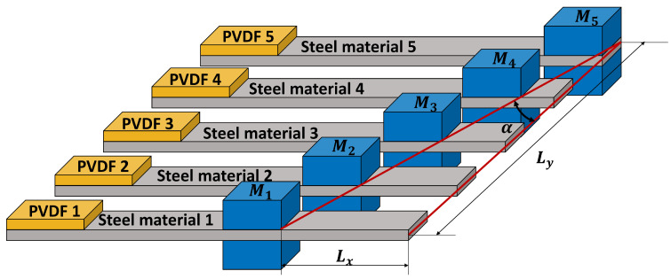 Figure 1
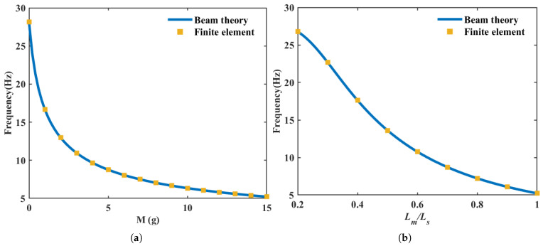 Figure 2
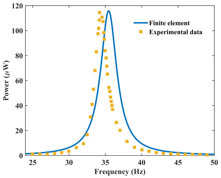 Figure 3
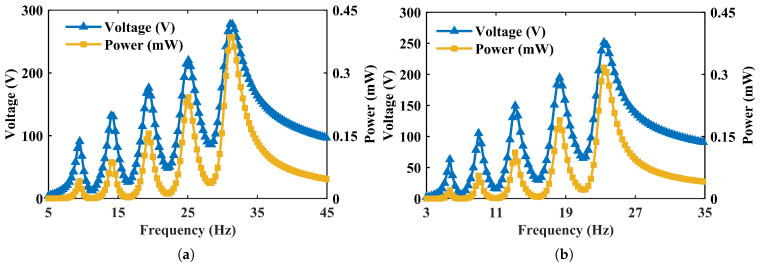 Figure 4
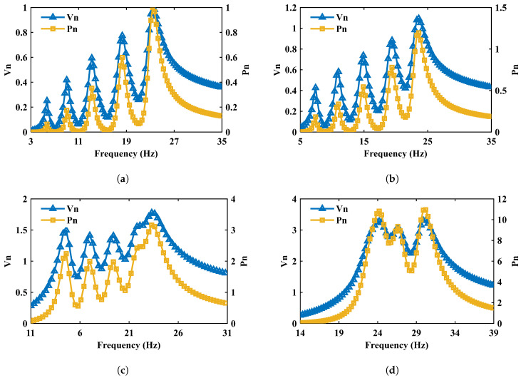 Figure 5
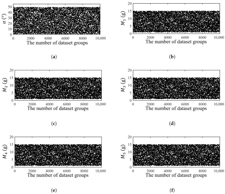 Figure 6
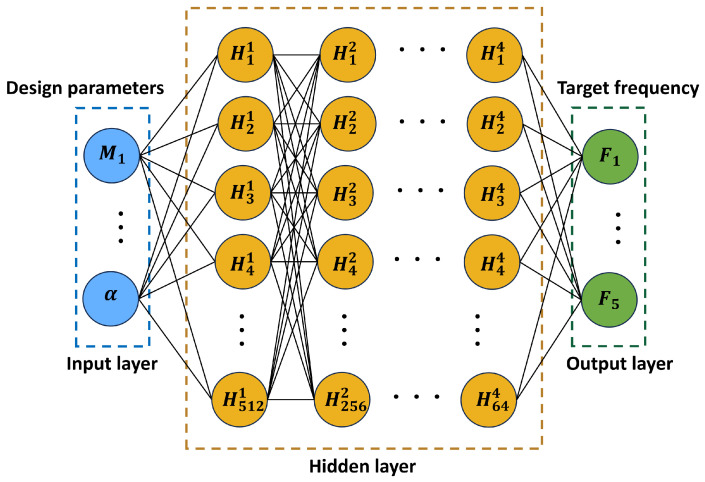 Figure 7
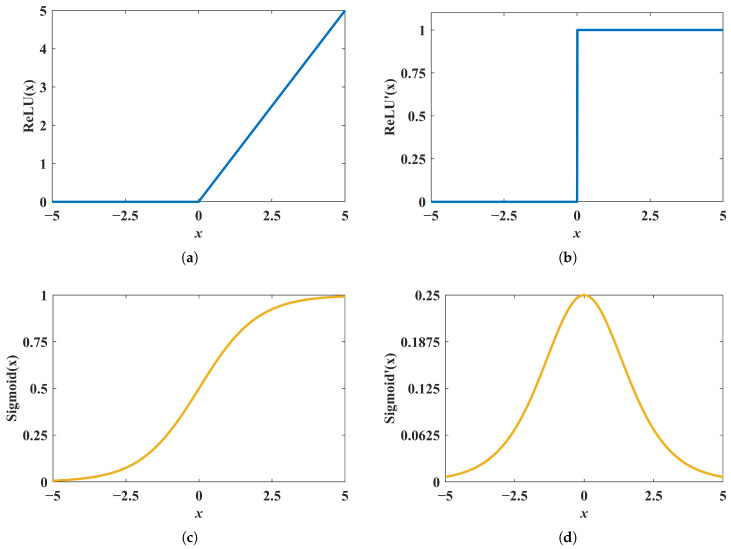 Figure 8
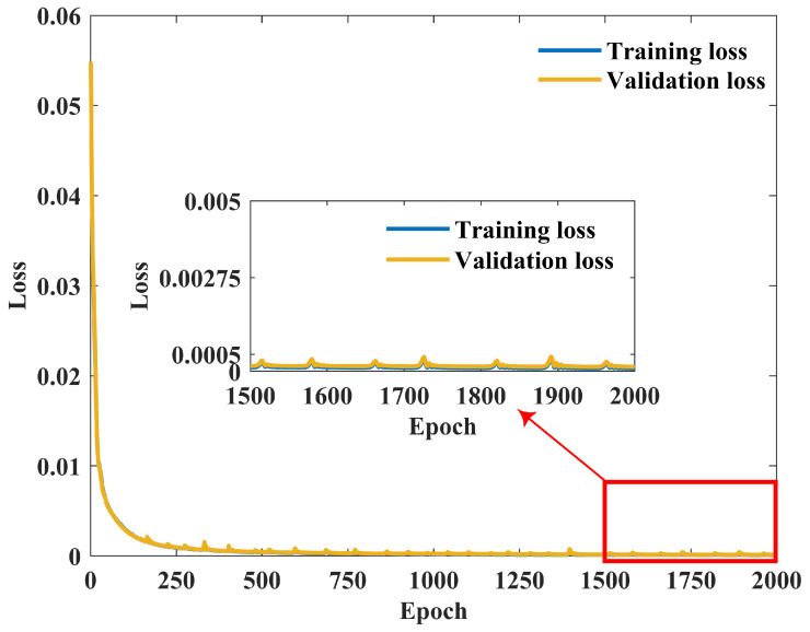 Figure 9
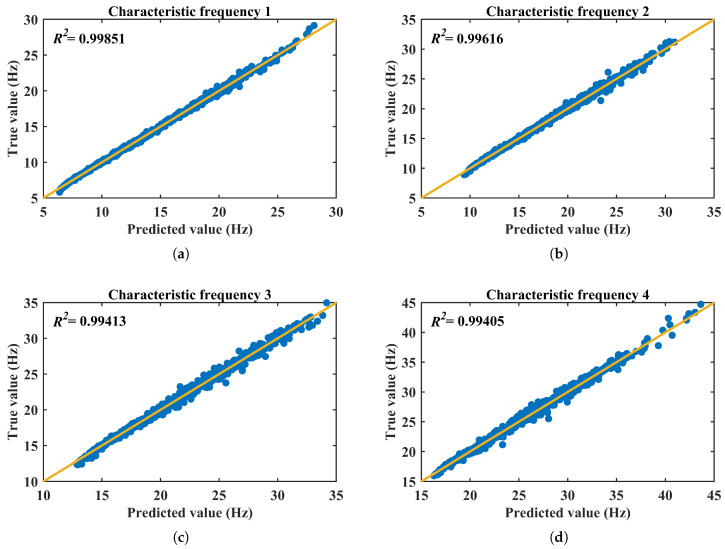 Figure 10
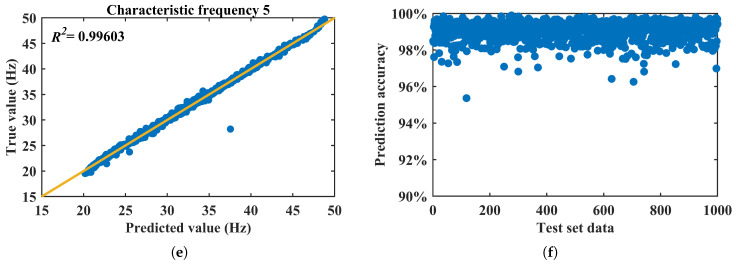 Figure 11
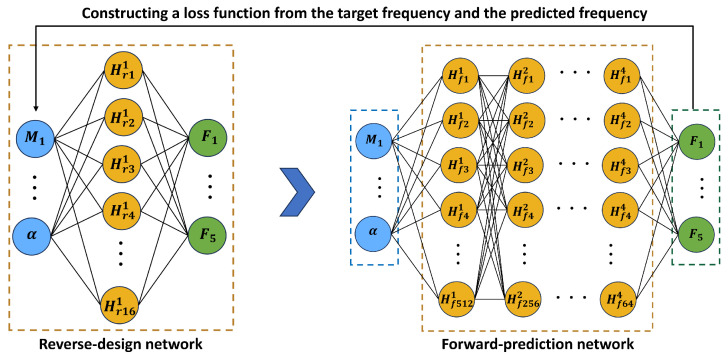 Figure 12
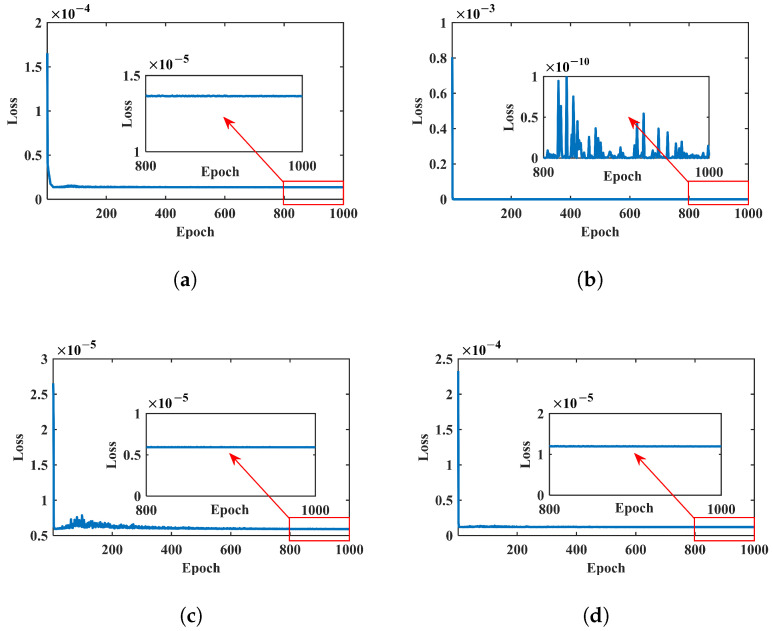 Figure 13
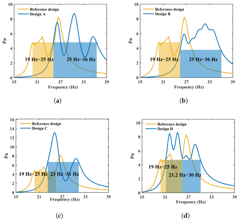 Figure 14
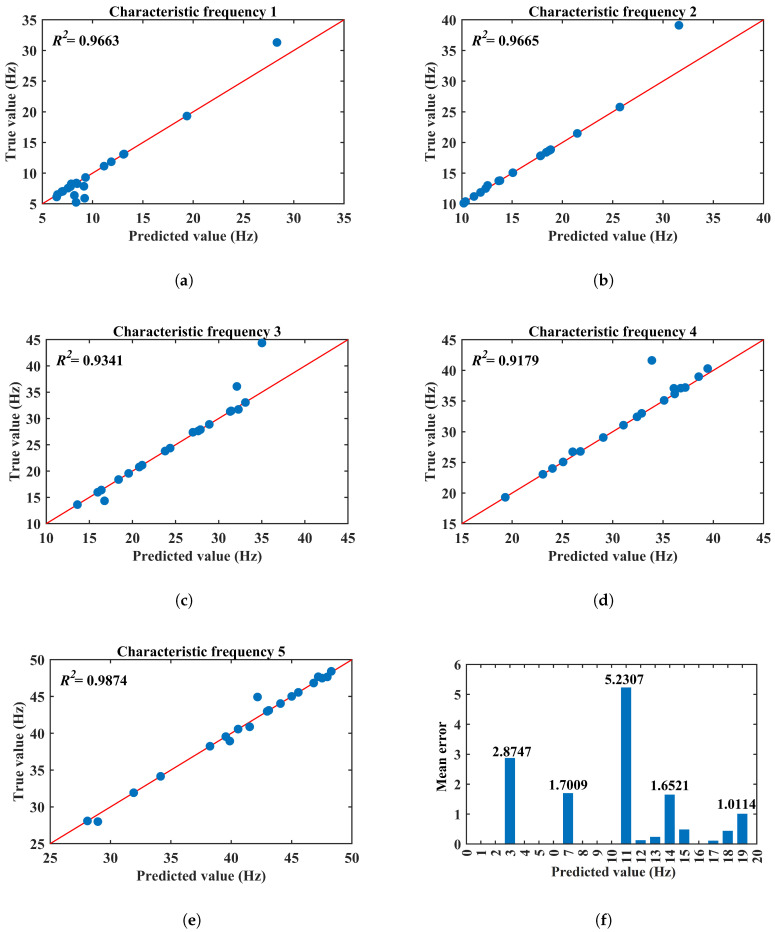 Figure 15
- —National Natural Science Foundation of China
- —Ningbo Municipal Natural Science Foundation
- —National Scientific Research Cultivation Project of Ningbo Polytechnic
Peer Reviews
No public reviews on file for this paper yet. If you reviewed it on a platform where reviews are public (OpenReview, ICLR, NeurIPS, ICML), you can paste yours below so the community can read it here.
Videos
No videos yet. Explain this paper in a talk, walkthrough, or lecture? Add one.
Taxonomy
TopicsInnovative Energy Harvesting Technologies · Energy Harvesting in Wireless Networks · Ferroelectric and Piezoelectric Materials
1. Introduction
Energy harvesting converts ambient energy into electrical power and offers a practical pathway toward self-powered low-power devices such as wireless sensor nodes [1,2], wearable electronics [3], and embedded monitoring systems [4,5], where battery replacement can be costly or impractical. In particular, the deployment of Internet of Things (IoT) sensor networks for long-term environmental and infrastructure monitoring imposes stringent requirements on energy autonomy, reliability, and adaptability to varying ambient vibrations [6]. Among common ambient sources, mechanical vibration is widely available in transportation, industrial equipment, and civil infrastructure, making vibration-driven energy harvesting an active research area. Piezoelectric energy harvesters are particularly attractive because they can generate relatively high voltage, they provide high energy density, and they can be miniaturized and integrated with micro-fabrication processes [7,8].
A persistent limitation of conventional linear PEHs is their inherently narrow operating bandwidth: peak output typically occurs near a single resonance, and performance drops sharply when the excitation frequency deviates from that point. In realistic environments, vibrations often have time-varying or broadband spectra, which motivates design methodologies that can broaden the effective operating frequency range without excessive structural complexity or impractical tuning requirements.
To address the bandwidth limitation, existing approaches can be broadly grouped into (i) nonlinear mechanisms and (ii) resonance tuning/tracking strategies [9]. Nonlinear harvesters—often based on bistability, multistability, magnetic interactions, or piecewise stiffness—can exhibit amplitude-dependent frequency responses and potentially broaden the response band under certain operating conditions [10,11]. However, nonlinear designs may introduce additional complexity, parameter sensitivity, and fabrication/integration challenges, and their broadband advantage can depend strongly on excitation levels and system damping. Resonance tuning methods, including adjustable proof masses and adaptive stiffness mechanisms, aim to shift the resonance to match changing excitation frequencies [12,13] but may require additional components, control strategies, or increased system complexity.
A complementary and scalable pathway is array-based broadband harvesting, where multiple cantilever beams are designed with staggered characteristic frequencies so that the aggregate response covers a wider band. In array PEHs, bandwidth broadening can be achieved by distributing end masses across beams and by modifying geometric or configuration parameters (e.g., mass block placement/tilt) to tailor individual resonances and superimpose multiple peaks [14,15]. While effective, array design introduces a practical bottleneck: as the number of design variables increases (e.g., multiple end masses plus configuration angles), the process of forward simulation and inverse tuning becomes high-dimensional, strongly coupled, and time-consuming if performed through repeated finite element method (FEM) sweeps.
This motivates data-driven design approaches that can replace or reduce costly FEM iterations. Recent years have seen rapid progress in surrogate modeling and parameter design using machine learning, particularly for complex multiphysics systems where direct optimization is expensive, such as in solving nonlinear partial differential equations [16,17] and designing elastic wave metamaterials [18,19,20,21,22,23,24]. In energy-harvesting research, modern studies increasingly combine simulation data with learning-based predictors to accelerate performance estimation and enable efficient optimization under realistic constraints [25,26].
In inverse design of mechanical metamaterials, a variety of data-driven approaches have been explored, including conditional GANs, invertible neural networks (INNs), and surrogate model with iterative optimization frameworks (e.g., Bayesian optimization) [27,28,29]. We adopt a tandem neural network (TNN) mainly because the performance to structure mapping in this problem is inherently a non-unique mapping; directly training an inverse network to regress a single ground-truth structural label can easily lead to overfitting and reduced design diversity. Instead, the TNN is trained in a forward-consistent manner—an inverse network proposes a design, a pre-trained forward model predicts its performance, and the loss is defined as the mismatch between the predicted and target performance—so that the solution is driven by the satisfaction of physical and target criteria rather than the reproduction of a particular training-sample geometry [27]. Moreover, compared with GAN-based methods that may suffer from training instability and limited controllability, as well as Bayesian-optimization-type methods that typically require multiple iterative evaluations for each new target, a TNN concentrates computation in a one-time offline training stage and can generate candidate designs for arbitrary targets via a single, fast inference step. This efficiency advantage—i.e., replacing expensive simulations with a learned surrogate to substantially accelerate optimization/inverse design—has also been quantitatively demonstrated in related studies [30].
In this work, we propose a data-driven inverse-design framework for a broadband piezoelectric energy harvester array using a TNN, building upon the array configuration studied by Kouritem et al. [14]. We choose the TNN formulation because the inverse mapping from target frequency sets to design parameters is inherently non-unique, and the tandem coupling trains the inverse network through a forward-consistency objective using a frozen, differentiable forward surrogate, which stabilizes learning under constraints and avoids iterative FEM-based tuning during inference. The key idea is to first learn an accurate forward surrogate that maps the design variables (end-mass distribution across beams and a configuration/tilt parameter) to the array’s characteristic frequencies using a large FEM-generated dataset, then couple this frozen forward surrogate with an inverse network so that the inverse-prediction mechanism is trained to satisfy target frequency sets while remaining within bounded, physically meaningful design ranges. This tandem coupling provides an efficient spectrum-to-parameter pathway for fast array customization and reduces reliance on repeated FEM trial-and-error tuning.
The remainder of this paper is organized as follows. Section 2 presents the PEH array configuration and the FEM-based dataset generation. Section 3 details the forward surrogate model and the tandem inverse-design architecture, including training strategy and constraint handling, and reports the validation results with discussions on design performance, robustness considerations, and comparison with baseline design approaches. Finally, Section 4 concludes the paper and outlines future extensions such as multi-objective power-based optimization, tolerance robustness analysis, and experimental verification.
2. Modeling and Simulation
2.1. Theoretical Modeling
Piezoelectric energy harvesters (PEHs) are primarily characterized by their resonance (modal) frequencies, which largely determine their operating performance. When the excitation frequency deviates from the resonant frequency, both the vibration amplitude and the electrical output drop significantly. Therefore, tuning the characteristic frequencies by adjusting structural parameters provides the foundation for improving harvesting efficiency and for realizing broadband responses.
To accurately describe the dynamic behavior of the array adopted in this study, which is a cantilever array with tunable tip masses, a segmented analytical model is established. As shown in Figure 1, each cantilever beam consists of three segments: Segment I ( ), a composite beam section formed by bonding a piezoelectric layer to an elastic substrate; Segment II ( ), a purely elastic substrate beam section; and Segment III ( ), and an elastic substrate beam section carrying a tip mass M. Here, the position of the proof mass, , is controlled by the inclination angle α (with ), which is one of the key design variables for achieving a broadband response from the array.
Based on the classical Euler–Bernoulli beam theory (neglecting shear deformation and rotary inertia), the equations governing the transverse vibration of each segment are as follows [31,32]:
where is the transverse deflection, is the equivalent bending stiffness, and is the mass per unit length. The subscripts correspond to the composite segment, the elastic segment, and the tip-mass tuning segment, respectively (see Appendix A for the detailed segmentation and parameters).
By applying separation of variables, the general solutions of the mode shapes and the dispersion relations can be obtained (see Appendix A for details). Under the boundary conditions at the clamped end ( ) and the free end ( ), together with the continuity conditions at the interfaces ( and ), the condition for nontrivial solutions can be reduced to the following characteristic equation for the circular frequency ω:
where is a coefficient matrix derived from the boundary and continuity conditions. The smallest positive real root gives the first natural circular frequency of the system, and the corresponding natural frequency is .
This analytical model fully accounts for the piezoelectric composite effect, geometric non-uniformity, and the inertial coupling associated with the tunable tip mass and thus can accurately capture how the stiffness and mass distributions regulate resonance. The high-accuracy analytical results provide a reliable validation benchmark for the finite element model in Section 2.2, thereby ensuring sufficient fidelity of the dataset used for subsequent neural-network training.
2.2. Finite Element Model and Validation
A single cantilever-beam piezoelectric energy harvester typically delivers its maximum output only near its characteristic frequency, which restricts performance under variable excitations. To broaden the operational band, multiple cantilever beams can be combined into an array so that their characteristic frequencies are distributed across a target range, thereby producing a broadband response. This array-based broadband strategy has been extensively investigated by Kouritem et al. [14], who used a five-beam array and tuned each beam’s resonance by adjusting the attached end-mass configuration. The present work follows the same array concept and adopts the model framework established in [14]. It is crucial to emphasize that the novelty of this study lies not in this established geometric configuration but in the introduction of a novel data-driven design framework to efficiently determine its optimal parameters ( and α) for target broadband performance. FE simulations are performed in COMSOL Multiphysics 6.2. The FE geometry (Figure 1) consists of five individual cantilever beams with end-mass blocks – attached to the free ends. The position/configuration of the mass blocks is characterized by a mass-block tilt angle α, defined by .
The substrate beam is modeled as steel and the piezoelectric layer is modeled as polyvinylidene fluoride (PVDF). The corresponding material properties are provided in Table 1 (e.g., the elastic modulus and density of the steel and the compliance, piezoelectric coefficient, permittivity, and density of the PVDF), and the geometric parameters are summarized in Table 2 (beam length/width and piezoelectric patch dimensions).
To validate the accuracy of the finite element (FE) model, a segmented-beam analytical model established in Section 2.1 was used to investigate the influence of the proof-mass parameters on the first natural frequency of a single cantilever, and the results were compared with the FE predictions.
Figure 2a shows the variation trend of the first natural frequency with respect to the proof mass M (from 0 g to 15 g) when the cantilever thickness is mm and the proof-mass position is set to . The analytical solutions agree closely with the FE results. Figure 2b further presents, for a fixed mass of g, the relationship between the frequency and the mass position (varying from to ), similarly demonstrating a high level of consistency between the two approaches.
These comparisons sufficiently verify the computational accuracy of the FE model in accounting for the effect of the proof mass, thereby providing a reliable numerical basis for the subsequent parametric analysis and data-driven design of the array.
To further validate the accuracy of the finite element (FE) modeling approach used to generate the complete dataset for this study, we benchmarked it against independent experimental data reported by Song et al. [33] for a PVDF-based energy harvester. Specifically, we replicated the two-layer PVDF cantilever beam structure described in the literature, which features an end mass of 1.872 g. In the simulation, the structure was subjected to the same base excitation acceleration as in the experiment, i.e., 0.5 g, with an isotropic loss factor of 0.07 and an optimal load resistance of applied across the electrical outputs. As shown in Figure 3, the frequency-dependent response (output voltage/power) predicted by our COMSOL model under these calibrated conditions shows excellent agreement with the measured results. This confirms the reliability of the finite element simulations employed in this study and their ability to accurately capture the electromechanical coupling response of the piezoelectric cantilever beam.
For electrical output evaluation, a resistive load is applied. Per Kouritem et al. [14], the optimal resistance is taken as . Under the excitation conditions reported in [14], the frequency response is computed with an excitation amplitude of 3.5 mm, and the output voltage and output power are extracted as the primary performance metrics for subsequent comparisons and for generating the learning dataset used in Section 3. This focus allows us to rigorously validate the TNN framework on a well-defined, high-dimensional parameter optimization problem within a proven structural configuration, while geometric parameters (e.g., beam length and width) are held constant to maintain consistency with the baseline model [14] and to isolate the efficacy of the proposed design method.
2.3. Parametric Analysis of Design Variables
In this subsection, we investigate the effects of the end-mass distribution ( – ) and the mass-block tilt angle α on the frequency-response characteristics of the five-beam PEH array. All simulations in this study, including those for the parametric analysis in this section and the generation of the 10,000-sample training dataset in Section 3, were conducted under a consistent set of conditions defined by the benchmark study [14]: a base excitation amplitude of 3.5 mm, a load resistance of , and a system damping factor of 0.09. Unless otherwise stated, all electrical quantities reported in this section (e.g., voltage and power) refer to peak values.
To enable a clear comparison of the influence of the tilt angle α on the output performance (including voltage, power, and operational bandwidth), we adopted the response of the graded mass distribution shown in Figure 4 ( , – ) as the baseline. Its peak voltage and peak power are denoted as and , respectively. The voltage and power responses for different values of α are then normalized, yielding the normalized voltage and normalized power . This consistent normalization method is also applied to the results of the inversely designed arrays in the following section for a fair performance evaluation.
Figure 4 compares the peak output voltage and peak output power responses under two representative mass configurations at : (i) a uniform distribution and (ii) a graded distribution , , , , and . The results show that changing the end-mass values shifts the operating (characteristic) frequencies of the individual cantilevers significantly, while the influence on the peak values of output voltage and power is comparatively small. This indicates that adjusting – is an efficient and direct lever to allocate the resonance peaks across a desired frequency band in the array configuration.
Figure 5 further investigates the influence of the tilt angle α while keeping the mass distribution fixed (the graded set above). Four angles are examined: , , , and . In contrast to mass tuning, α affects not only the locations of the resonance peaks but also the overall levels of output voltage and power. Notably, a pronounced broadband effect emerges when , and the output power becomes substantially higher than that at . These trends are consistent with the observations reported in the reference array study, supporting the reliability of the present FE simulations.
The above results demonstrate that the end-mass distribution – primarily controls the allocation of characteristic frequencies, whereas the tilt angle α provides a strong additional mechanism for broadband enhancement. Therefore, – and α are selected as the key design variables for the data-driven forward prediction and the tandem-network parameter design developed in Section 3.
3. Deep Learning Neural Network
Figure 3 and Figure 5 demonstrate that the end-mass distribution – and the mass-block tilt angle α have a strong influence on the characteristic frequencies and broadband response of the five-beam array harvester. Accordingly, the design-parameter vector is defined as , and the corresponding characteristic-frequency vector is defined as . The overall strategy in this section is to first train a fast forward surrogate that approximates the finite element mapping , then construct a constrained inverse-design model that maps target frequencies without requiring expensive FE evaluations during optimization.
3.1. Forward-Prediction Network for Predicting Operating Frequency
To enable fast parameter design of the array energy harvester, we first construct a forward surrogate to replace repeated FE simulations. In the inverse-design context, the target is a prescribed characteristic-frequency set, while the design variables are the five end-mass values ( – ) and the mass-block tilt angle (α). Embedding FE simulations in the learning loop would require running COMSOL at each iteration to obtain the corresponding operating frequencies, which is computationally inefficient. Therefore, we generate a simulation dataset using COMSOL and train a neural-network-based forward-prediction model to approximate the FE mapping from design variables to characteristic frequencies. Once trained, this model provides a low-cost and differentiable forward simulator for subsequent parameter design. To generate the training dataset, the six design variables were sampled within the bounded design space and . Each variable was independently drawn from a uniform distribution over its allowed range, and each sampled design point was evaluated by COMSOL to obtain the corresponding characteristic-frequency vector . Figure 6 visualizes the resulting 10,000 samples and shows that all variables span the full prescribed ranges without obvious clustering, indicating adequate coverage of the design space for training the surrogate model.
An MLP is adopted as the forward-prediction network because it can approximate complex nonlinear relationships using stacked fully connected layers. As shown in Figure 7, the network input is the six-dimensional design vector , where – denote the end-mass values of the five cantilever beams and α characterizes the mass-block configuration. The network output is the five-dimensional frequency vector – , representing the characteristic frequencies of the array harvester. Nonlinear activation functions are required to enhance representational capacity and ensure stable training. A ReLU is used in the hidden layers to mitigate gradient vanishing/explosion and improve convergence in deep fully connected architectures, whereas a sigmoid function is used at the output layer to constrain predictions to after normalization. Figure 8 illustrates the function curves and derivatives of and , clarifying their respective roles in the network.
The forward network is trained using supervised learning on a dataset generated from FE simulations. The dataset contains 10,000 samples and is split as follows: 80% for training, 10% for validation, and 10% for testing. The learning objective is to minimize the mean squared error (MSE) between predicted frequencies and FE ground truth:
where L is the loss, n is the output dimension ( ), is the FE value of the ith output frequency, and is the corresponding network prediction. The forward MLP is implemented in TensorFlow and trained for 2000 epochs using the Adam optimizer with a learning rate of . The network architecture comprises five fully connected layers with neuron counts of 512, 256, 128, 64, and 5, respectively. Batch normalization is applied after each hidden layer, and ReLU activation is used in the hidden layers, while the output layer uses a sigmoid activation function to constrain predictions to the normalized range . The batch size is set to the full training set per iteration because each design configuration is unique. Early stopping is not applied, as the training converged stably within 2000 epochs, as shown in the learning curve (Figure 9).
To evaluate prediction performance on unseen samples, the coefficient of determination ( ) is used:
where is the mean of the true values. Figure 10 reports the test-set verification results. Figure 10a–e compare the predicted and true characteristic frequencies for beam 1 to beam 5, respectively, using the 1000 samples in the test set. In each figure, the data points cluster closely around the diagonal line, indicating strong agreement between the MLP predictions and the FE results. The reported values are consistently high for all five outputs (approximately 0.994–0.999), confirming that the forward model captures the nonlinear mapping from – to – with high fidelity. Figure 10f summarizes the overall prediction accuracy across the 1000 test samples; the manuscript reports that the test-set accuracy exceeds 90% and that the inference time is less than 1 s. These results demonstrate that the forward-prediction MLP can reliably replace repeated FE evaluations and provide the foundation for the constrained inverse-design framework introduced in the next subsection.
3.2. Constrained Parameter Design Using a TNN and FE Verification
Although the forward-prediction MLP in Section 3.1 can accurately predict the characteristic frequencies of the array harvester, using it for parameter design by directly updating the design variables through gradient descent may lead to unsatisfactory or even incorrect results. The main reason is that, without constraints, the optimized design parameters can drift beyond the learning domain of the MLP, where the surrogate model may misjudge the frequency response. Therefore, constraints must be imposed on the design variables to prevent the optimization from “falling into the wrong area.” In the present work, this is achieved by connecting an inverse-design network to the trained forward-prediction network so that the inverse network’s output range is naturally limited by its output-layer activation, while still enabling end-to-end training through a frequency-mismatch loss. This coupled structure is referred to as a tandem neural network (TNN) [34].
Figure 11 illustrates the complete TNN pipeline for parameter design. The target operating-frequency set (i.e., the set of desired characteristic frequencies) is first fed into the inverse-design network. The inverse network outputs a candidate parameter set (mass-block values and tilt angle). These predicted parameters are then passed into the forward-prediction network trained in Section 3.1, which outputs the corresponding predicted operating frequencies. The predicted frequencies and the target frequencies together form the loss function. During training, only the inverse-design network is updated: it continuously optimizes its internal weights and biases to minimize the frequency mismatch, while the forward-prediction network acts as a fixed surrogate evaluator. In this way, the parameter design remains data-supported and bounded but can still be optimized efficiently using backpropagation.
The inverse network is implemented in TensorFlow and trained using the Adam optimizer with an initial learning rate of and an exponential decay schedule (decay rate of 0.8 every 5000 steps). The network architecture comprises one hidden layer with 16 neurons, using tanh activation, followed by an output layer with six neurons (corresponding to the five end masses and the tilt angle) with Sigmoid activation to constrain outputs to the normalized range . The training is performed for 100,000 epochs with a batch size of one (each target frequency set is processed individually). The forward-prediction MLP remains fixed during this process, and only the inverse network weights are updated to minimize the mean squared error between the target and predicted characteristic frequencies.
Figure 12 shows the convergence (loss) curves of the TNN inverse-design training for four representative target characteristic-frequency sets (Groups A–D). The rapid decrease in the loss indicates efficient convergence of the constrained inverse-design process for all target sets. After convergence, the corresponding inverse-designed parameters are obtained. For example, the solution for Group D yields Design B with and masses – , , , , and .
The COMSOL results confirm that the TNN can accurately generate the array parameters needed to realize the desired broadband response; for the four design cases, the resulting −3 dB bandwidth is approximately 10 Hz, demonstrating that the proposed TNN-based inverse-design strategy produces physically valid broadband array PEH designs when validated by FE analysis. Notably, the performance of these TNN-generated designs (see Figure 13) compares favorably with the optimized design from [14], which represents the state of the art achieved through an exhaustive parameter sweep. This demonstrates that our data-driven inverse design framework is not only efficient but also capable of synthesizing high-performance solutions that match or surpass those found by traditional, computationally expensive optimization methods.
To further verify the generalizability of the TNN within the trained design domain, we performed an additional inverse-design test on 20 randomly generated target-frequency sets. The results (detailed in Appendix B) show that the model maintains good inverse-prediction accuracy ( ) over most of the domain, with a slight error increase only for a few designs whose parameters lie near the domain boundaries. This boundary-region performance can be further improved in future work by augmenting training samples near the limits or by adaptive sampling strategies.
4. Conclusions
This study demonstrates that the end-mass distribution – and the tilt angle α serve distinct and complementary functions in broadband PEH array design: the masses primarily dictate the allocation of resonant frequencies, while the tilt angle is key to enhancing the bandwidth and output level through modified system dynamics, consistent with prior physical insights [14]. Building on this understanding, this paper develops a data-driven inverse-design workflow for a five-beam PEH array using a tandem neural network (TNN). A forward MLP surrogate is trained using 10,000 FE-generated samples to learn the mapping from the design variables to the characteristic frequencies, achieving high predictive accuracy and sub-second inference. Building on the trained surrogate, an inverse-design network is coupled with the frozen forward network to form the TNN, enabling direct spectrum-to-parameter design under bounded and physically feasible ranges. For two representative target frequency groups, the TNN converges rapidly and produces corresponding mass/tilt designs, and independent FE simulations verify that the designed arrays achieve broadband frequency responses with bandwidths exceeding 10 Hz. From a practical standpoint, this spectrum-to-parameter pathway enables rapid customization of array harvesters for site-specific and time-varying vibration spectra, which is particularly valuable for deploying self-powered sensing nodes where the dominant excitation frequencies are uncertain or drifting.
In contrast to traditional FEM-driven design workflows (e.g., manual parameter sweeps or iterative optimization that repeatedly calls high-fidelity FE simulations for each target), the proposed TNN framework shifts most of the computational cost to an offline dataset-generation/training stage and then avoids repeated FE evaluations during parameter design. As a result, candidate designs can be generated efficiently through the differentiable surrogate and backpropagation, while the final designs remain reliable because they are constrained within the admissible parameter bounds and are independently validated by COMSOL simulations. This combination of computational efficiency and verified design quality highlights the practical value of the proposed approach for rapid customization of PEH arrays under varying target spectra, substantially reducing engineering time and dependence on trial-and-error FEM tuning. In future practical developments, the proposed workflow can be integrated into an engineering design loop in which field-measured vibration spectra are first translated into target characteristic-frequency sets, followed by near-instant parameter generation via the trained TNN and a small number of FE or experimental checks for final verification. Such an approach can significantly shorten the design cycle for broadband PEH arrays and facilitate scalable, application-specific deployment (e.g., for machine-condition monitoring, structural health monitoring, and distributed IoT sensor networks) without relying on exhaustive parameter sweeps.
The current approach is limited by the predefined training domain ( and ), and parameter designs outside the learned ranges may degrade in accuracy; moreover, the present parameter design targets characteristic frequencies using mass/tilt parameters only. Future work will incorporate power-oriented objectives (including load/circuit matching), evaluate robustness under manufacturing tolerances (e.g., perturbations in and α), extend the design space to additional geometric variables (e.g., beam length/width and patch layout), and include experimental validation on fabricated prototypes; multi-objective formulations (e.g., multi-band power targets) will also be explored to enable application-specific broadband and high-efficiency designs. In addition, integrating the inverse-designed PEH arrays with power-management electronics and storage modules and coupling the framework with in situ spectral identification may further enable practical system-level prototypes that deliver more stable power under realistic broadband and nonstationary vibrations.
The reference list from the paper itself. Each links out to its DOI / PubMed record.
- 1Makki N. Pop-Iliev R. Battery-and Wire-Less Tire Pressure Measurement Systems (TPMS) Sensor Microsyst. Technol.2012181201121210.1007/s 00542-012-1480-6 · doi ↗
- 2Peigney M. Siegert D. Piezoelectric Energy Harvesting from Traffic-Induced Bridge Vibrations Smart Mater. Struct.20132209501910.1088/0964-1726/22/9/095019 · doi ↗
- 3Izadgoshasb I. Lim Y.Y. Lake N. Tang L. Padilla R.V. Kashiwao T. Optimizing Orientation of Piezoelectric Cantilever Beam for Harvesting Energy from Human Walking Energy Convers. Manag.2018161667310.1016/j.enconman.2018.01.076 · doi ↗
- 4Dagdeviren C. Yang B.D. Su Y. Tran P.L. Joe P. Anderson E. Xia J. Doraiswamy V. Dehdashti B. Feng X. Conformal Piezoelectric Energy Harvesting and Storage from Motions of the Heart, Lung, and Diaphragm Proc. Natl. Acad. Sci. USA 20141111927193210.1073/pnas.131723311124449853 PMC 3918766 · doi ↗ · pubmed ↗
- 5Ali F. Raza W. Li X. Gul H. Kim K.-H. Piezoelectric Energy Harvesters for Biomedical Applications Nano Energy 20195787990210.1016/j.nanoen.2019.01.012 · doi ↗
- 6Paccoia V.D. Bonacci F. Clementi G. Cottone F. Neri I. Mattarelli M. Toward Field Deployment: Tackling the Energy Challenge in Environmental Sensors Sensors 202525561810.3390/s 2518561841012858 PMC 12473342 · doi ↗ · pubmed ↗
- 7Wu N. Bao B. Wang Q. Review on Engineering Structural Designs for Efficient Piezoelectric Energy Harvesting to Obtain High Power Output Eng. Struct.202123511206810.1016/j.engstruct.2021.112068 · doi ↗
- 8Moon K. Choe J. Kim H. Ahn D. Jeong J. A Method of Broadening the Bandwidth by Tuning the Proof Mass in a Piezoelectric Energy Harvesting Cantilever Sens. Actuators A 2018276172510.1016/j.sna.2018.04.004 · doi ↗