Differential Reflecting Frequency Modulation with QAM for RIS-Based Communications
Yajun Fan, Le Zhao, Wencai Yan, Haihua Ma

TL;DR
This paper introduces a new communication system using reconfigurable surfaces that reduces the need for channel information and improves performance with a new modulation technique.
Contribution
The paper introduces DRFM with QAM, a novel modulation scheme that enhances throughput and performance without requiring channel state information.
Findings
DRFM operates without channel state information at the transmitter, RIS, or receiver.
The proposed QAM-aided DRFM outperforms traditional PSK, APSK, and star-QAM modulations.
Simulation results show DRFM has acceptable SNR penalty compared to coherent detection methods.
Abstract
Reconfigurable intelligent surface (RIS)-aided index modulation (IM) shows great potential for next-generation wireless communications. Nevertheless, obtaining channel state information (CSI) for RIS-based IM incurs high pilot overhead, particularly for multi-domain IM. In this paper, we integrate orthogonal frequency division multiplexing into RIS-aided differential reflecting modulation (DRM) communications, introducing the differential reflecting frequency modulation (DRFM) system. In DRFM, information bits are jointly conveyed through the activation permutations of reflecting patterns, grouped carriers, and constellation symbols. The transmitter combines the differentially coded reflecting-time block and the time–frequency block using the Kronecker product. This allows DRFM to operate without relying on CSI at the transmitter, RIS, or receiver. Moreover, we design a novel high-rate…
Click any figure to enlarge with its caption.
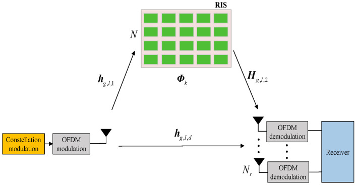 Figure 1
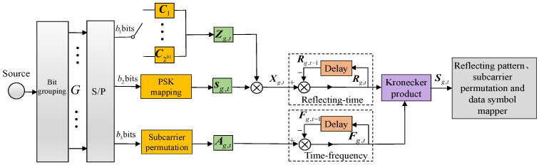 Figure 2
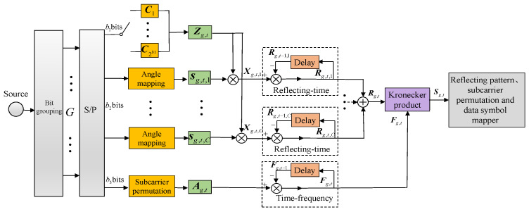 Figure 3
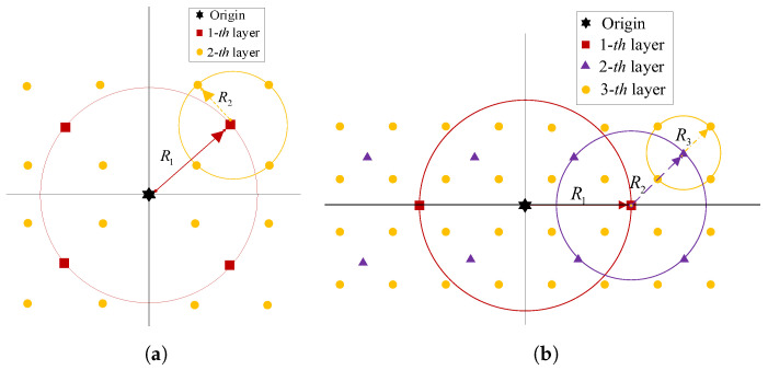 Figure 4
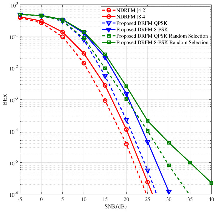 Figure 5
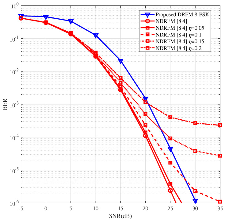 Figure 6
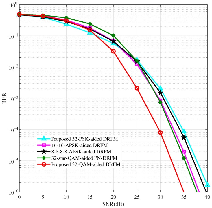 Figure 7
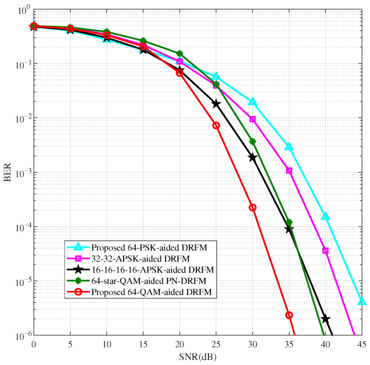 Figure 8
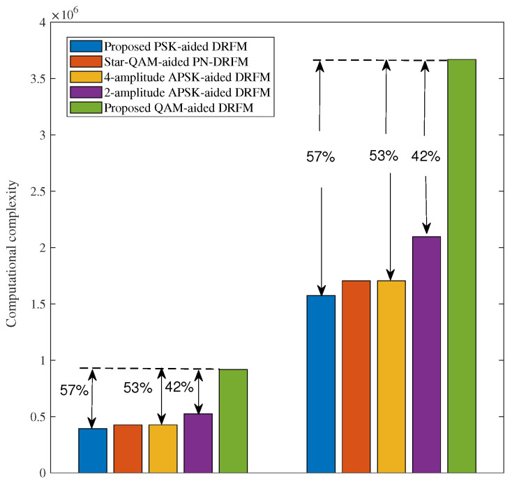 Figure 9
- —Natural Science Foundation of Henan
- —Cultivation Project of National Natural Science Foundation of Henan University of Technology
- —Doctoral Foundation of Henan University of Technology
- —Open Fund of Laboratory of Grain Information Processing and Control of Henan University of Technology
- —Key R&D and Promotion Projects in Henan Province
Peer Reviews
No public reviews on file for this paper yet. If you reviewed it on a platform where reviews are public (OpenReview, ICLR, NeurIPS, ICML), you can paste yours below so the community can read it here.
Videos
No videos yet. Explain this paper in a talk, walkthrough, or lecture? Add one.
Taxonomy
TopicsAdvanced Wireless Communication Technologies · Advanced Wireless Communication Techniques · Advanced Antenna and Metasurface Technologies
1. Introduction
1.1. Background
Owing to its advantages in energy efficiency and error performance, index modulation (IM) is a promising technology for sixth-generation wireless communications [1,2,3,4]. The IM technique conveys additional bits via common resources such as antennas [5,6,7], frequencies [8,9], timeslots [10], codes [11], and beamspace. As another emerging IM technique, reconfigurable intelligent surface (RIS)-based reflection modulation (RM) regards different reflection patterns of the RIS as the index entities of IM signals [12,13]. The RIS consists of a substantial number of low-cost passive reflective elements. These elements, with the assistance of an intelligent controller, are capable of modulating the phase shift and amplitude gain of the passive reflection of incident electromagnetic waves [14]. By leveraging the dimension of reflection patterns, the RM technology enhances the channel gain of the communication system.
However, the receivers in all of the aforementioned schemes focus on IM for coherent communications, in which highly precise channel state information (CSI) is of the utmost necessity for signal detection [15,16,17]. Whether in traditional multiple-input multiple-output (MIMO) wireless communication systems or in RIS-assisted MIMO systems, channel estimation is a challenging and resource-intensive task. Additionally, the performance degradation resulting from channel estimation errors is unavoidable. To circumvent complex channel estimation, a commonly adopted approach is to employ differential modulation [18] for the joint IM entity across diverse domains. Leveraging the time dimension, differential spatial modulation (DSM), a representative non-coherent modulation scheme in the spatial domain, encodes a portion of the information bits within the activated antenna index matrices of a space-time block. By means of differential processing implemented at the transmitter, coupled with the corresponding non-coherent detection strategies employed at the receiver, DSM eliminates the requirement for highly accurate CSI and further reduces the complexity.
Inspired by DSM, the differential reflecting modulation (DRM) scheme was introduced for RIS-based communication systems [19,20], where additional information bits are conveyed via the activation permutation of the reflecting patterns. To further augment the beamforming gain of RIS, a method integrating RIS beam training and differential phase shift keying modulation at the transmitter was proposed [21]. Additionally, to eliminate the requirement for synchronizing the transmitted bits at both the transmitter and the RIS, an RIS-assisted differential transmitted spatial modulation was put forward [22], where the DSM-encoding process is implemented at the transmit antennas, with a single antenna activated per timeslot. Although the aforementioned RIS-based communication schemes [19,21] can avoid resource-consuming channel estimation, they operate solely within a single domain of IM. Consequently, this leads to low transmission efficiency.
1.2. Related Works and Motivations
In terms of boosting the transmission efficiency, very few existing studies [23,24,25,26] have focused on dual-domain differential modulation for RIS-enabled communication systems. Specifically, in [23], two differential schemes, namely DRM-aided spatial modulation and DSM-aided reflecting modulation, were presented, which are designed for joint differential IM in both the space and reflection domains [24]. To further enhance the bit error rate performance and decrease the decoding complexity, the authors of [25] proposed a multi-domain joint rectangular differential IM system that utilizes RF mirrors. This scheme devises a space media precoding codebook, which serves to jointly regulate the activation patterns of RF mirrors and antenna activation, enabling more efficient mapping within the space media domain. Similarly, the authors of [26] put forward the rectangular differential reflecting spatial modulation system, where a rectangular dispersion matrix is utilized to jointly map a digital beamforming weight vector and an RIS reflection pattern, thereby performing rectangular differential modulation. However, the studied RIS-based differential communication systems do not take frequency-domain resources into account. To address such limitations, we focus on differential reflecting frequency modulation (DRFM) for the RIS-aided communication system.
It is well known that, in most existing research on differential modulation systems, constant-modulus constellations—for instance, phase shift keying (PSK)—are adopted at the differential encoder [18]. Nevertheless, choosing such a constellation results in either reduced throughput or deteriorated error rate performance because of the small minimum distance in PSK. To increase the minimum distance while maintaining the constellation size, the authors of [27] put forward two-ring amplitude phase shift keying (APSK) modulation for the DSM system. A power level change coefficient normalizes the transmit signal power during differential processing between the rings of the APSK constellation. It has been shown that APSK-modulated DSM systems improve the bit error rate (BER) performance relative to conventional PSK-modulated DSM. Analogously, the authors of [28] presented a multi-ring amplitude phase modulation scheme. Through an in-depth analysis of the average bit error probability, the ratio of rings within the multi-amplitude constellation was optimized, which led to a further enhancement in the BER performance in the DSM system. In [29], a generalized transmission scheme, namely the precoding-normalized DSM scheme, was proposed for constant-modulus constellation modulation. Through normalizing the power of all symbols in the preceding transmit matrix during differential transmission, the BER performance was further improved. Different from the above modulation schemes, the authors of [30] proposed a quadrature amplitude modulation (QAM) method and applied it to the DSM system. The transmitted QAM constellation is encoded and transmitted in a hierarchical differential manner through the composite phase shift method. Inspired by the above idea, a non-constant QAM constellation modulation scheme is studied for the proposed DRFM system in this work.
1.3. Contributions
Compared with existing work, the main contributions of this study are summarized as follows:
- DRM is generalized from single-carrier to multi-carrier scenarios for RIS-based communications. In DRFM, information bits are jointly conveyed through the activation permutations of reflecting patterns, grouped carriers, and constellation symbols.
- An overall DRFM transceiver design is presented. The transmitter integrates the differentially coded reflecting-time block and the time–frequency block using the Kronecker product. At the receiver, differential detection allows operation without acquiring CSI.
- A non-constant QAM constellation modulation scheme is studied for the proposed DRFM system. The transmitted QAM constellation is encoded and transmitted in a hierarchical differential manner through the composite phase shift method.
1.4. Organization and Notations
The remainder of this paper is organized as follows. Section 2 describes the PSK-aided DRFM system, including the system description and transceiver design. Section 3 details the QAM-aided DRFM system, covering the transmitter design and receiver detection. Simulations are presented in Section 4, and Section 5 concludes the paper.
Notations: , and a stand for a matrix, a vector and a scalar, respectively. denotes the transpose operator of a vector. represents the Frobenius norm of a vector. indicates that a row vector is transformed into a diagonal matrix. stands for the floor operation. denotes the modulo operation. The identity matrix is represented by . The complete list of acronyms is presented in Table 1.
2. PSK-Aided DRFM System
2.1. System Description
In this work, we consider an RIS-based single-input multiple-output (SIMO) orthogonal frequency division multiplexing (OFDM) communication system model, as illustrated in Figure 1. represents the number of receiver (Rx) antennas, and N denotes the number of RIS reflecting units. Given the differential encoding mechanism at the transmitter (Tx), in this section, the Tx is tasked with sending M-ary phase shift keying (PSK) symbols.
Assume that the OFDM modulator is composed of F subcarriers, which are partitioned into G groups. Each group g contains subcarriers. For group g, subcarrier l, let , , and stand for the channel vector between the RIS and the Tx, the channel matrix between the Rx and the RIS, and the channel vector between the Rx and the Tx, respectively. The channels are modeled as quasi-static Rayleigh fading channels, similarly to [19]. Unlike conventional RIS-aided systems, where the RIS passively improves the channel conditions, the proposed DRFM scheme brings about a paradigm shift. In this new approach, the RIS itself functions as an active information modulator in the spatial domain. This forms the fundamental reflecting dimension of our index modulation. Specifically, a predefined codebook consisting of K distinct reflection patterns is defined as . Each candidate pattern is a diagonal matrix. The n-th diagonal entry satisfies for an ideal phase-shifting element or 0 to represent an inactive element, with a phase shift . During the transmission process, a subset of these patterns is actively selected over time in accordance with the input data bits. In this way, information is directly embedded into the wireless channel through controlled reflections. This dynamic, information-driven reconfiguration of the RIS represents the physical implementation of reflecting modulation in DRFM.
2.2. Transceiver Design
2.2.1. Differential Encoding Scheme
At the Tx, the original input bit stream is divided into G branches. Each branch comprises bits. During transmission, a block will occupy L symbol timeslots, such that . As shown in Figure 2, at group g, time instant t, the first bits are used to select the reflecting-time permutation matrix . Similarly to DSM, there are valid permutation matrices, namely . In the mapping process, however, only matrices are chosen for the mapping operation. The other are mapped into K M-ary PSK symbols . Finally, the rest are used to select the time–frequency permutation matrix . Assume that, over L subcarriers, the permutation of the activated reflecting patterns in K time instants stays constant. Under this premise, according to [9], the spectral efficiency of DRFM can be expressed as
where is the length of the cyclic prefix added at the Tx.
Assume that the Tx and the RIS can achieve good synchronization; the reflecting-time block that contains both the reflection pattern and symbol information can be expressed as
Based on differential encoding, the new time–frequency matrix and reflecting-time matrix are separately generated as
where and , respectively, represent the time–frequency matrix and the reflecting-time matrix of group g at the previous time instant. At group g, time instant t, a non-zero element located at the position of indicates that subcarrier n at timeslot w is activated to convey information. Similarly, a non-zero element at the position of signifies that reflection pattern m at timeslot w is activated to transmit the modulated symbol . When , and are designated as initial matrices. By leveraging the Kronecker product [9] to integrate the three-dimensional information of the reflection pattern, time, and frequency, the transmitted two-dimensional matrix can be formulated as
Assume that and , respectively, denote the sets encompassing all possible forms of and in Equation (5). For DRFM, it is necessary to satisfy the following: (1) given that and , then ; (2) given that and , then .
2.2.2. Channel Model
According to [9], at group g, the frequency-domain channel coefficient matrix can be expressed as
where represents the frequency-domain channel matrix of subcarrier l in group g. Specifically, according to [19], the matrices , , , and are, respectively, set as
where Equations (7)–(10) formulate the aggregated channel matrices for subsequent derivations. In particular, Equation (7) aligns the direct path with each candidate RIS pattern. Equations (8) and (10) expand the RIS–receiver and RIS–transmitter channels, respectively, to match the dimensions of the RIS pattern set. Equation (9) encompasses all K possible reflection patterns from which the transmission patterns need to be selected within a finite set. Given that neither the transceivers nor the RIS have access to the CSI, we adopt the optimization criterion put forward in [19]. The objective of this criterion is to maximize the minimum mutual Euclidean distance, thereby enabling the derivation of all K reflection patterns. The mentioned formulations offer a concise foundation for the system model presented in Equation (11). Furthermore, although RIS commonly assists blocked links, the direct path is included to maintain model generality. It can be set to zero when the direct path is not present.
2.2.3. ML Detector
At the Rx, the received matrix at group g, time instant t can be expressed as
where denotes the complex additive white Gaussian noise matrix with zero mean and .
Substituting Equations (3)–(5) into Equation (11) yields
In the aforementioned equation, we simplify it by leveraging the “mixed-product property” of the matrix product and Kronecker product. Specifically, given that , , , and are four matrices such that the matrix products and are well defined, the property holds. By virtue of this property and Equation (11), Equation (12) can be transformed into
where denotes the received noise of the Rx at group g, time instant t.
Consequently, the optimal maximum-likelihood (ML) detector can function without any knowledge of CSI by
where and are the sets of all legitimate and , respectively. Equation (14) is solved by a joint exhaustive search over all valid combinations of the reflecting pattern matrix from and the symbol matrix from . The pair that minimizes the Frobenius norm metric is selected. Decoding involves three parallel streams of bit recovery corresponding to the three bit partitions, i.e., , , and . First, the time–frequency permutation bits are directly recovered by performing a codebook lookup on the estimated matrix . The core of decoding lies in the decomposition of the reflecting-time block, defined as , where is a permutation matrix. Crucially, the specific permutation pattern of the matrix can be directly identified from the unique position of the non-zero element in each row of the estimated . This allows the receiver to unambiguously determine which predefined permutation matrix was transmitted. Once is known, the estimated constellation symbol vector is obtained by applying the inverse permutation to the vector of non-zero elements extracted from . Finally, the remaining bits are recovered. The identified matrix undergoes a second codebook lookup to recover the reflection pattern index bits. Simultaneously, the constellation bits are demapped. For PSK, is processed by a standard PSK demapper.
3. QAM-Aided DRFM System
As is well known, a differential modulation system demands a differential coding mechanism at the transmitter. Thus, in Section 2, we put forward a PSK-based DRFM system to circumvent amplitude accumulation problems in the differential process. For high-order modulation, compared to non-constant-modulus modulations like QAM, PSK modulation has a smaller minimum Euclidean distance between constellation points. This results in the relatively poor bit error performance of the differential system. To tackle this issue, we propose conducting the hierarchical transmission of the QAM constellation. In each layer, PSK is utilized for differential coding and transmission. This approach serves to prevent the issue of amplitude accumulation during the transmission of the QAM constellation. To further mitigate error propagation effects, we introduce QAM into the DRFM system.
3.1. Transmitter Design
A block diagram of the proposed QAM-aided DRFM transmitter is given in Figure 3. Similarly to the PSK-aided Tx mapping scheme in Section 2, bits and bits are employed to select the reflecting-time permutation matrix and the time–frequency permutation matrix , respectively. The difference is that the bits are mapped into K M-ary QAM symbols ( , ). Figure 4 depicts the QAM constellation diagrams of various orders. Specifically, Figure 4a shows 16-QAM and Figure 4b represents 32-QAM. Here, denotes the total number of superimposed layers. Evidently, each QAM symbol is formed by superimposing multiple independent layers of BPSK or QPSK symbols. From Figure 4a, the 16-QAM modulation symbol is obtained by vectorially adding the first-layer QPSK vector (the four square points on the red circle) and the second-layer QPSK vector (the four dot points on the yellow circle). The bit mapping of modulation symbols in each layer is accomplished via distinct angle mappings. The angular vector of the c-th layer’s modulation symbols can be denoted as ( ). If m is odd, the first-layer angular mapping rule is as follows: when the one bit , the mapping results in ; when , the mapping gives . When m is even, the first-layer angular mapping rule is as follows: when the two bits , and 11, the mapping results in and , respectively.
Based on the angle mapping, the transmission signal vector of layer c is obtained as . From this, the reflecting-time block of layer c is
By means of differential encoding processing, the reflecting-time transmission matrix of layer c can be expressed as
where need to satisfy the following conditions:
- (1)If m is odd, the initial matrix of the 1st layer is ; Conversely, when m is even, . For other layers ( ), . Here, ( ) and ( ) denote the magnitudes of constellation mapping for each layer.
- (2)The same reflecting-time permutation matrix is assigned across all layers. This assignment guarantees that, for in different layers, each column and row has only one non-zero value at the same position.
After superimposing all layers, according to [30], the final reflecting-time transmission matrix can be expressed as
where each column and row of has precisely one non-zero value, meaning that, at each instant, only one reflection mode is activated exactly once in K consecutive timeslots.
The differential encoding processing of the time–frequency transmission block is in accordance with Equation (3). As in Equation (5), the final fused two-dimensional matrix can be formulated as
3.2. Receiver Detection
At the receiver, the frequency-domain signal matrix received in group g, time instant t can be expressed as
where . Similarly, the zero-noise received matrix in group g, time instant , layer c is . According to Equations (12) and (13), can also be expressed as
Substituting Equation (20) into Equation (19) yields
where is the set of all legitimate in layer c. Equation (21) fundamentally relies on a search over the finite alphabets of and the per-layer symbols . The search space is extended to jointly cover the reflecting pattern and the set of per-layer symbol matrices , each from its corresponding constellation set . Similarly to the PSK-aided DRFM system, once is known, the estimated layer symbol vector is obtained by applying the inverse permutation to the vector of non-zero elements extracted from each per-layer block . Then, each layer’s vector is first PSK-demapped, and the resulting bits from all C layers are then recombined according to the transmitter’s superposition rule to reconstruct the original high-order QAM symbol bits. When m is odd, for the first layer ( ), the initial zero-noise received matrix is defined as . For the subsequent layers with , the initial zero-noise received matrices are expressed as . When m is even, for each layer with , the initial zero-noise received matrix is set to . In accordance with Equations (21) and (22), the receiver requires the previous -th time–frequency permutation matrix and the reflecting-time signal matrix to determine the zero-noise received matrix for the detection process in the current t-th block. Consequently, any amplitude errors in the detected signal may give rise to the issue of error accumulation and propagation.
4. Simulations and Analysis
In this section, we showcase the simulation results of the proposed DRFM system and the applicable high-order QAM modulation scheme. To demonstrate the BER performance of the proposed DRFM system, we compare DRFM with non-DRFM (NDRFM). In NDRFM, perfect CSI (i.e., perfect , , and ) is adopted for coherent detection. Notably, to ensure a fair comparison, the Kronecker product is incorporated into the operational framework of NDRFM as well. Under this premise, the spectral efficiency of NDRFM can be expressed as
To further verify the BER performance of the high-order QAM scheme suitable for DRFM, we incorporate two-amplitude APSK modulation [27] and four-amplitude APSK modulation [28] into the proposed DRFM system. Moreover, we implement the precoding normalized (PN) scheme cited in reference [29] within the DRFM framework, obtaining a PN-DRFM system based on star-QAM modulation for a comparative analysis. In the comparison, we consider an RIS with elements, each using 1-bit coding ( ), resulting in valid reflecting patterns. Following [19], patterns are selected via the stepwise depletion algorithm. The related simulation parameters are listed in Table 2. The SNR is . The carrier frequency is set as GHz.
In Figure 5, we present and compare the BER performance of the proposed PSK-aided DRFM and NDRFM in RIS-based reflecting-frequency dual-domain IM schemes. For an SE of 1.2 bps/Hz, DRFM uses QPSK modulation, while NDRFM uses mixed QPSK and BPSK modulation. For an SE of 1.6 bps/Hz, DRFM employs 8-PSK modulation, and NDRFM adopts mixed 8-PSK and QPSK modulation. To ensure fairness, both systems employ ML detection. Figure 5 illustrates that, under the given simulation setups, DRFM is at a 3–4 dB disadvantage relative to NDRFM, while eliminating the receiving end’s need to acquire CSI. For further comparison, in Figure 5, we include the BER of DRFM with the reflecting pattern selection in [19] and contrast it with random selection, demonstrating the superiority of this reflecting pattern selection.
Recall that, in the previous simulation, perfect CSI was assumed for NDRFM. However, NDRFM demands substantial resources for channel estimation, and perfect CSI is rarely available. To evaluate the impact of CSI estimation errors on performance degradation, in Figure 6, we further compare the proposed DRFM and NDRFM with imperfect CSI. From Figure 6, the performance of NDRFM deteriorates notably as the CSI estimation error rises. When , the performance gap between DRFM and NDRFM is small. When , in the high-SNR range, DRFM with coherent detection outperforms NDRFM, with NDRFM showing a significant floor effect.
To further validate the effectiveness and reliability of the high-order QAM modulation scheme, we apply the proposed QAM and existing non-constant-modulus modulation schemes [27,28,29] to DRFM for performance comparison. Figure 7 and Figure 8 display the BER performance comparison of DRFM using QAM, multi-amplitude APSK (two-amplitude and four-amplitude APSK), PSK, and PN-DRFM using star-QAM for and modulations, with spectral efficiencies of 2.4 bit/s/Hz and 2.8 bit/s/Hz, respectively. Ref. [27] states that the two amplitudes of two-amplitude APSK are . Refs. [28,29] indicate that the optimal amplitude ratios of four-amplitude APSK and star-QAM are identical. For and , their optimal amplitude ratios are 1.5 and 1.35, respectively.
As shown in Figure 7 and Figure 8, in the high-SNR region, the BER performance of the proposed QAM-aided DRFM system is better than that of the star-QAM-aided PN-DRFM system and the multi-amplitude APSK and PSK-aided DRFM systems. This is due to the relatively uniform distribution of QAM constellation points, leading to the highest utilization of spatial degrees of freedom. Among the other modulation methods, the utilization of spatial degrees of freedom, from high to low, follows the order of star-QAM, multi-amplitude APSK, and PSK. As shown in Figure 7, the QAM intersects with PSK at an SNR of 16 dB. The intersection points of several other modulation methods with PSK are between approximately 15 dB and 23 dB. At BER = , when compared to the DRFM systems employing PSK, two-amplitude APSK (16-16-APSK, where two concentric rings each contain 16 phase points), four-amplitude APSK (8-8-8-8-APSK, where four rings each contain 8 points), and the PN-DRFM system using star-QAM, the QAM-based DRFM system achieves performance gains of approximately 6 dB, 3.5 dB, 5 dB, and 3 dB, respectively. In Figure 8, where and at a BER of , relative to the DRFM systems using PSK, two-amplitude APSK (32-32-APSK), and four-amplitude APSK (16-16-16-16-APSK), and the PN-DRFM system with star-QAM, the QAM-based DRFM system attains performance gains of around 10 dB, 8 dB, 4.5 dB, and 4 dB, respectively.
Table 3 compares the complexity of different constellation modulations within one carrier group of DRFM—specifically, the number of real-valued multiplication operations required. Here, B denotes the number of bits transmitted in one reflecting-time–frequency block. As shown in Table 3, necessitates real-valued multiplication operations. The 2-norm operation demands real-valued multiplication operations. The QAM scheme presented in this paper partitions the QAM constellation into C-layer differential transmissions. Consequently, the number of real-valued multiplications grows by a factor of relative to PSK. Thus, it exhibits the highest computational complexity. Figure 9 depicts the complexity comparison under specific settings: , , and and 64. Relative to PSK, star-QAM, four-amplitude APSK, and two-amplitude APSK, the complexity of the QAM-based DRFM system increases by approximately 57%, 53%, 53%, and 42%, respectively. Nevertheless, as is evident from Figure 8, when and , compared to the DRFM systems using PSK, two-amplitude APSK, and four-amplitude APSK, and the PN-DRFM system using star-QAM, the proposed QAM-aided DRFM system achieves performance gains of around 10 dB, 8 dB, 4.5 dB, and 4 dB, respectively.
5. Conclusions
In this paper, we generalize DRM from single-carrier to multi-carrier scenarios and propose the DRFM system for RIS-based communications. In DRFM, the transmitter integrates the differentially coded reflecting-time block and the time–frequency block using the Kronecker product. At the receiver, differential detection allows operation without acquiring CSI. Moreover, a non-constant QAM constellation scheme is explored for the DRFM system. The transmitted QAM constellation is encoded and transmitted hierarchically and differentially via the composite phase shift method. Numerical simulations have been carried out to validate the advantages of the DRFM system and the applicable QAM constellation modulation scheme in terms of the BER. The performance was evaluated under ideal synchronization as a baseline to validate the core concept. Future work will investigate robustness to synchronization errors and extend this CSI-free paradigm to multi-user scenarios, leveraging classical RIS phase optimization techniques.
The reference list from the paper itself. Each links out to its DOI / PubMed record.
- 1Cheng X. Zhang M. Wen M. Yang L. Index modulation for 5G: Striving to do more with less IEEE Wirel. Commun. Mag.20182512613210.1109/MWC.2018.1600355 · doi ↗
- 2Basar E. Wen M. Mesleh R. Di Renzo M. Xiao Y. Haas H. Index modulation techniques for next-generation wireless networks IEEE Access 20175166931674610.1109/ACCESS.2017.2737528 · doi ↗
- 3Wen M. Chen X. Li Q. Basar E. Wu Y.-C. Zhang W. Index Modulation Aided Subcarrier Mapping for Dual-Hop OFDM Relaying IEEE Trans. Commun.2019676012602410.1109/TCOMM.2019.2920642 · doi ↗
- 4Zhou Y. Liu L. Wang L. Hui N. Cui X. Wu J. Peng Y. Qi Y. Xing C. Service-aware 6G: An intelligent and open network based on the convergence of communication, computing and caching, Digital Communications and Networks Digit. Commun. Netw.2020525326010.1016/j.dcan.2020.05.003 · doi ↗
- 5Mesleh R.Y. Haas H. Sinanovic S. Ahn C.W. Yun S. Spatial modulation IEEE Trans. Veh. Technol.2008572228224110.1109/TVT.2007.912136 · doi ↗
- 6He L. Wang J. Song J. Spatial modulation for more spatial multiplexing: RF-chain-limited generalized spatial modulation aided mm-wave MIMO with hybrid precoding IEEE Trans. Commun.20186698699810.1109/TCOMM.2017.2773543 · doi ↗
- 7Fan Y. Wu J. Guo Y. Yang J. Zhao L. Yan W. Yang S. Ma H. Zhu C. DAF-Aided ISAC Spatial Scattering Modulation for Multi-Hop V 2V Networks Sensors 202525618910.3390/s 2519618941095015 PMC 12527024 · doi ↗ · pubmed ↗
- 8Basar E. Aygolu U. Panayirci E. Poor H.V. Orthogonal frequency division multiplexing with index modulation IEEE Trans. Signal Process.2013615536554910.1109/TSP.2013.2279771 · doi ↗