Recent Advances in Mediator and Proton Relay Usage in Molecular Catalysis
Yu‐Lin Chi, Wei‐Shuo Chuang, Jing‐Ke Lin, Yu‐Heng Wang

TL;DR
This paper reviews recent advances in using mediators and proton relays to improve molecular catalysts for energy-related reactions.
Contribution
The paper systematically benchmarks the use of EPTMs, RMs, and PRs in molecular catalysis using kinetic and thermodynamic analyses.
Findings
EPTMs, RMs, and PRs enhance catalytic efficiency in reactions involving CO2, O2, H2O, and N2.
Linear free energy relationships and catalytic Tafel plots provide insights into reaction mechanisms and selectivity.
The review offers a foundation for the rational design of molecular catalysts for energy conversion.
Abstract
Electron–proton transfer mediators (EPTMs), redox mediators (RMs), and proton relays (PRs) have been incorporated into diverse homogeneous molecular catalysts to enhance catalytic efficiencies in the reactions of energy‐related small molecules (e.g., CO2, O2,H2O, and N2) and organic compounds. However, the benefits of using EPTMs, RMs, and PRs in molecular catalysis have not been comprehensively or quantitatively benchmarked. This review highlights the latest developments in this field, focusing on the kinetics, thermodynamics, and selectivities of multiple proton–electron redox processes, as well as their corresponding advantages. The reaction mechanisms, linear free energy relationships, and catalytic Tafel plots are considered to provide a solid foundation for evaluating these catalytic systems and the strategic development of molecular catalysts. These efforts are expected to…
Genes, proteins, chemicals, diseases, species, mutations and cell lines named across the full text — each resolved to its canonical identifier and authoritative record.
Click any figure to enlarge with its caption.
 Scheme 1
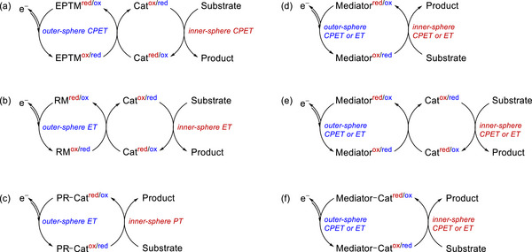 Scheme 2
 Figure 1
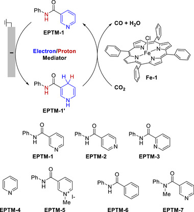 Figure 2
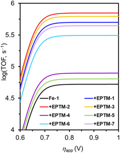 Figure 3
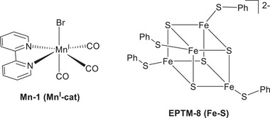 Figure 4
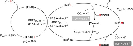 Figure 5
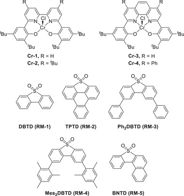 Figure 6
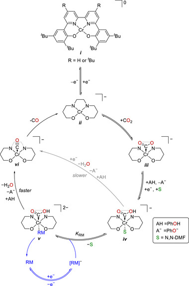 Figure 7
 Figure 8
 Figure 9
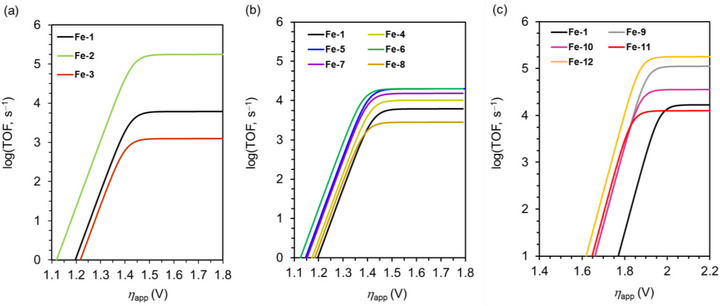 Figure 10
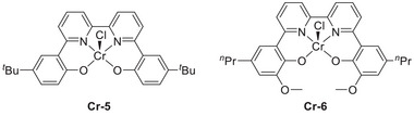 Figure 11
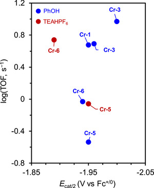 Figure 12
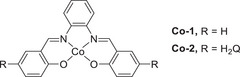 Figure 13
 Figure 14
 Figure 15
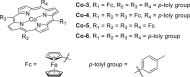 Figure 16
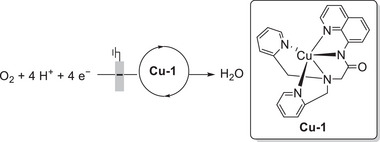 Figure 17
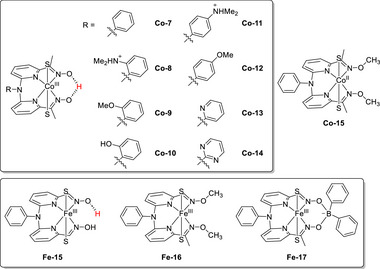 Figure 18
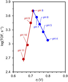 Figure 19
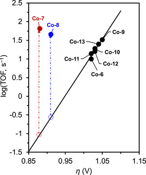 Figure 20
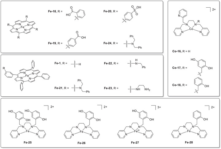 Figure 21
 Figure 22
 Figure 23
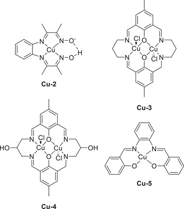 Figure 24
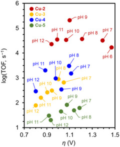 Figure 25
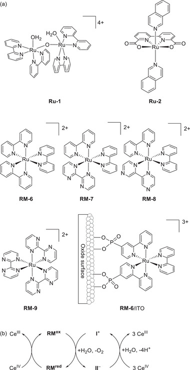 Figure 26
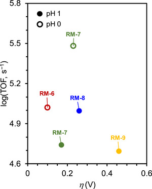 Figure 27
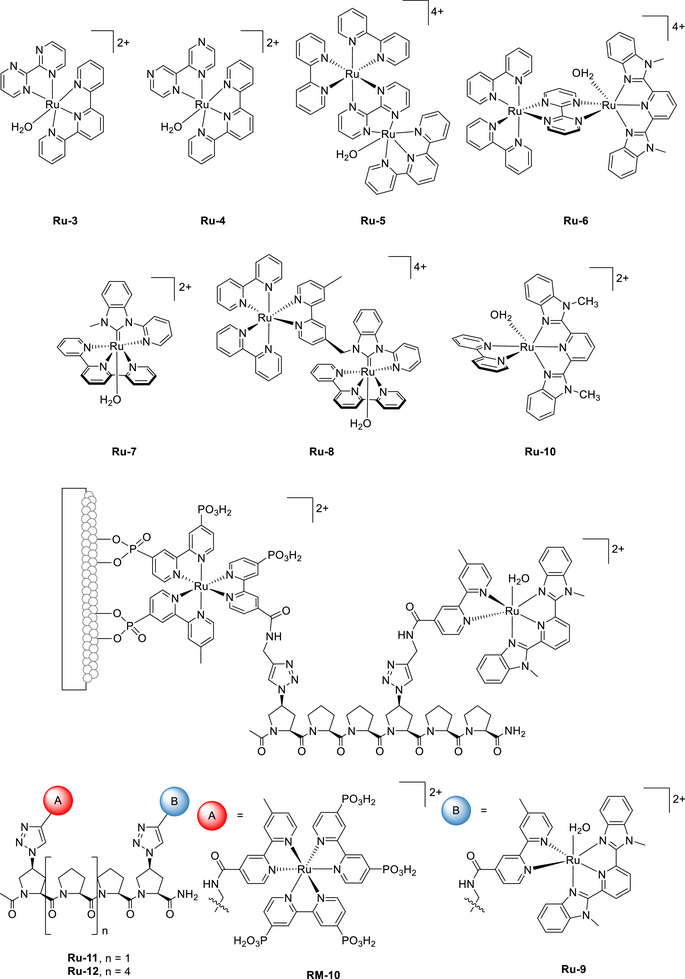 Figure 28
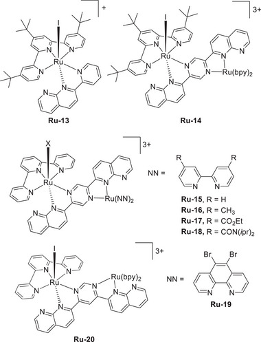 Figure 29
 Figure 30
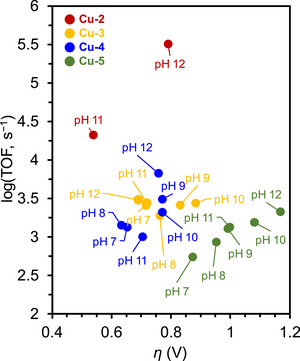 Figure 31
 Figure 32
 Figure 33
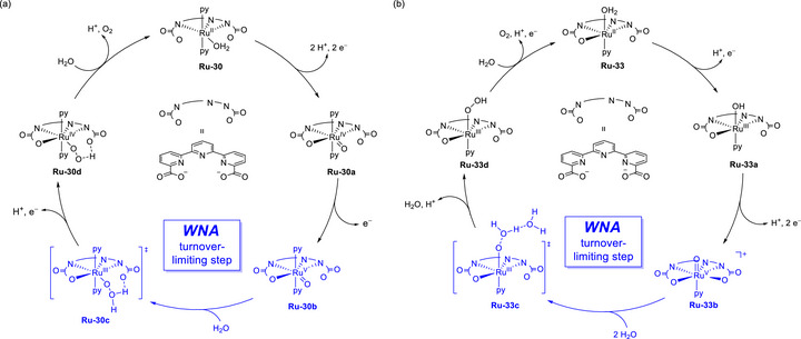 Figure 34
 Figure 35
 Figure 36
 Figure 37
 Figure 38
 Figure 39
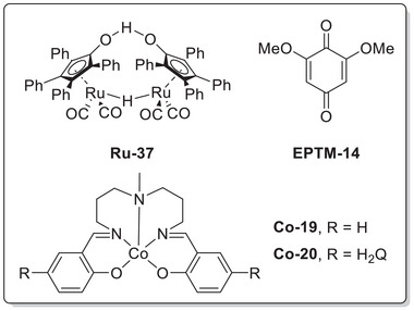 Figure 40
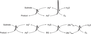 Figure 41
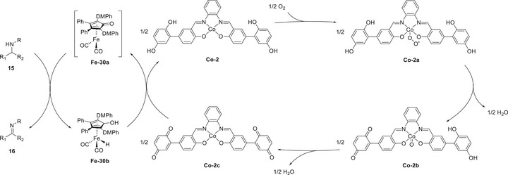 Figure 42
 Figure 43
 Figure 44
 Figure 45
 Figure 46
 Figure 47
| Catalyst/EPTM | Charge [C] |
FECO [%] |
[mA cm−2] |
TOFmax [s−1] |
|
|---|---|---|---|---|---|
|
| 41.8 | 93 | 0.67 | 5.24 × 10⁴ | 0.660 |
|
| 119.2 | 86 | 2.07 | 5.00 × 10⁵ | 0.659 |
|
| 141.0 | 108 | 2.45 | 7.01 × 10⁵ | 0.658 |
|
| 132.7 | 87 | 2.31 | 6.23 × 10⁵ | 0.659 |
|
| 50.4 | 94 | 0.82 | 7.85 × 10⁴ | 0.659 |
|
| 46.0 | 92 | 0.74 | 6.39 × 10⁴ | 0.658 |
|
| 94.5 | 104 | 1.63 | 3.10 × 10⁵ | 0.660 |
|
| 112.5 | 100 | 1.95 | 4.44 × 10⁵ | 0.659 |
| Conditions |
| FECO / FEHCOOH [%] | TOF [s−1] |
|
|---|---|---|---|---|
|
| −1.85 | 91/0 | – | 0.22 |
|
| −1.85 | 0/30 | – | 0.22 |
|
| −1.85 | 9/87 | – | 0.22 |
|
| −1.85 | 6/92 | 20.3 ± 2 | 0.22‐0.34 |
|
| −1.70 | 6.7/91 | 0.46 | 0.07‐0.19 |
|
| −1.65 | 3/78 | 0.4 | 0.02‐0.14 |
|
| −2.05 | 32/56 | – | 0.42‐0.54 |
| Entry | Condition | Potential (V vs Fc+/Fc) | FECO [%] | TOFCPE [s−1] |
|
|---|---|---|---|---|---|
| 1‐A |
| −2.30 | 111 ± 14 | 7.12 | 0.11 |
| 1‐A' |
| −2.30 | 95 ± 8 | 9.29 | 0.16 |
| 1‐A" |
| −2.30 | 111 ± 14 | 7.12 | 0.11 |
| 1‐b |
| −2.30 | 91 ± 10 | 36.8 | 0.69 |
| 1‐B |
| −2.30 | 102 ± 12 | 65.3 | 0.41 |
| 1‐B' |
| −2.30 | 102 ± 14 | 65.3 | 0.41 |
| 1‐C |
| −2.25 | 98 ± 17 | 74.5 | 0.35 |
| 1‐D |
| −2.30 | 98 ± 6 | 64 | 0.4 |
| 1‐E |
| −2.20 | 100 ± 2 | 69.3 | 0.28 |
| 2‐A |
| −2.30 | 95 ± 8 | 9.29 | 0.16 |
| 2‐B |
| −2.30 | 109 ± 9 | 163 | 0.41 |
| 2‐C |
| −2.25 | 97 ± 6 | 208 | 0.35 |
| 2‐D |
| −2.30 | 98 ± 4 | 149 | 0.4 |
| 2‐E |
| −2.20 | 97 ± 5 | 194 | 0.28 |
| 2‐F |
| −2.20 | 100 ± 2 | 63.4 | 0.12 |
| 3‐A |
| −2.30 | 101 ± 3 | 4.9 | 0.12 |
| 3‐B |
| −2.30 | 94 ± 7 | 56.3 | 0.41 |
| 3‐E |
| −2.20 | 102 ± 3 | 126 | 0.28 |
| 3‐F |
| −2.20 | 103 ± 5 | 328 | 0.12 |
| 4‐A |
| −2.10 | 91 ± 3 | 0.24 | 0.09 |
| 4‐B |
| −2.30 | 77 ± 2 | 27.4 | 0.41 |
| 4‐F |
| −2.20 | 97 ± 5 | 34 | 0.12 |
|
| |||
|---|---|---|---|
| Catalyst | TOF [s−1] |
| Refs. |
|
| 6.17 × 10³ | 1.42 | [ |
|
| 1.78 × 10⁵ | 1.43 | [ |
|
| 1.26 × 10³ | 1.40 | [ |
|
| 1.02 × 10⁴ | 1.41 | [ |
|
| 2.00 × 10⁴ | 1.401 | [ |
|
| 2.00 × 10⁴ | 1.38 | [ |
|
| 1.51 × 10⁴ | 1.40 | [ |
|
| 2.82 × 10³ | 1.388 | [ |
|
| 1.12 × 10⁵ | 1.90 | [ |
|
| 3.55 × 10⁴ | 1.87 | [ |
|
| 1.26 × 10⁴ | 1.83 | [ |
|
| 1.78 × 10⁵ | 1.91 | [ |
|
| 4.80 × 10² | − | [ |
|
| 1.00 × 10² | − | [ |
| Conditions |
| FECO [%] | TOF [s−1] |
|
|---|---|---|---|---|
|
| −1.95 | 96 ± 8 | 4.75 | 0.11 |
|
| −2.00 | 95 ± 8 | 9.29 | 0.16 |
|
| −1.96 | 101 ± 3 | 4.9 | 0.12 |
|
| −1.95 | 85 ± 3 | 0.29 | 0.09 |
|
| −1.95 | 83 ± 1 | 0.87 | 0.70 |
|
| −1.94 | 99 ± 3 | 0.93 | 0.06 |
|
| −1.89 | 103 ± 5 | 5.47 | 0.66 |
|
| |||
|---|---|---|---|
| Catalyst | Acid conc. [mM] | H2O2 [%] | H2O [%] |
|
| − | 45 | − |
|
| − | 27 | − |
|
| 30 | 97 | 3 |
|
| 30 | 20 | 80 |
|
| ||||
|---|---|---|---|---|
| Catalyst |
(V vs (SCE) |
(V vs SCE) |
| H2O2 [%] |
|
| 0.20 | 0.19 | 2.1 | 95 |
|
| 0.14 | 0.13 | 2.0 | 100 |
|
| 0.30 | 0.29 | 2.1 | 95 |
|
| 0.07 | 0.05 | 2.8 | 60 |
| pH | % H2O2 |
| TOF [s−1] |
|---|---|---|---|
| 4 | 3 | 0.799 | 1.2 (±0.01) × 103 |
| 5 | 4 | 0.773 | 1.8 (±0.01) × 103 |
| 6 | 11 | 0.752 | 2.63 (±0.02) × 103 |
| 7 | 25 | 0.735 | 3.72 (±0.02) × 103 |
| 8 | 31 | 0.714 | 5.07 (±0.02) × 103 |
| 9 | 42 | 0.701 | 2.81 (±0.01) × 103 |
| 10 | 57 | 0.682 | 9.50 (±0.01) × 102 |
| 11 | 65 | 0.659 | 4.71 (±0.01) × 102 |
| Catalyst |
|
| TOF [s−1] |
|---|---|---|---|
|
| −0.51 | 1.02 | 10 |
|
| −0.37 | 0.88 | 65 |
|
| −0.40 | 0.91 | 46 |
|
| −0.54 | 1.05 | 33 |
|
| −0.52 | 1.03 | 19 |
|
| −0.51 | 1.02 | 14 |
|
| −0.50 | 1.03 | 16 |
|
| −0.53 | 1.04 | 25 |
|
| |||||
|---|---|---|---|---|---|
| Catalyst | TOF [s−1] |
| Solvent | % H2O2 | Refs. |
|
| 27 | 1.08 | DMF | − | [ |
|
| 1.59 | 1.20 | MeCN | − | [ |
|
| 200 | − | DMF | <2% | [ |
|
| 2000 | 1.18 | DMF | − | [ |
|
| 15 | 1.04 | DMF | 〜9% | [ |
|
| 1800 | 1.09 | DMF | − | [ |
|
| 1601 | 1.095 | DMF | − | [ |
|
| 10.30 | 1.08 | MeCN | − | [ |
|
| 3960 | 1.052 | DMF | − | [ |
|
| 2970 | 1.08 | DMF | − | [ |
|
| 12.30 | 1.01 | MeCN | − | [ |
|
| 14.6 | 0.58 | MeCN | 92 | [ |
|
| 3.3 | 0.42 | MeCN | 83 | [ |
|
| 3.2 | 0.37 | MeCN | 81 | [ |
|
| − | 0.41 | MeCN | 26 | [ |
|
| − | − | MeCN | − | [ |
|
| 0.31 | 0.33 | MeCN | 61 |
[
[
|
|
| 0.32 | 0.31 | MeCN | 11 | [ |
|
| ||||
|---|---|---|---|---|
| Catalyst | pH | TOF [s−1] |
| Refs. |
|
| 6 | 1.7 × 10⁴ | 1.47 | [ |
|
| 7 | 3.2 × 10⁴ | 1.39 | [ |
|
| 8 | 3.7 × 10⁴ | 1.21 | [ |
|
| 9 | 2.1 × 10⁵ | 1.10 | [ |
|
| 10 | 3.4 × 10⁴ | 1.07 | [ |
|
| 11 | 3.5 × 10⁴ | 0.99 | [ |
|
| 12 | 2.3 × 10⁴ | 0.94 | [ |
|
| 7 | 664.589 | 1.048 | [ |
|
| 8 | 899.618 | 1.001 | [ |
|
| 9 | 313.223 | 0.943 | [ |
|
| 10 | 260.894 | 0.903 | [ |
|
| 11 | 161.623 | 0.847 | [ |
|
| 12 | 78.669 | 0.802 | [ |
|
| 7 | 1521.027 | 1.113 | [ |
|
| 8 | 3066.521 | 1.095 | [ |
|
| 9 | 346.724 | 1.028 | [ |
|
| 10 | 950.114 | 0.977 | [ |
|
| 11 | 2011.736 | 0.885 | [ |
|
| 12 | 290.256 | 0.802 | [ |
|
| 7 | 61.743 | 1.188 | [ |
|
| 8 | 50.072 | 1.138 | [ |
|
| 9 | 83.183 | 1.076 | [ |
|
| 10 | 44.813 | 1.025 | [ |
|
| 11 | 30.36 | 0.917 | [ |
|
| 12 | 20.254 | 0.934 | [ |
| Catalyst | Mediator | pH |
|
| TOF [s−1] |
| Refs. |
|---|---|---|---|---|---|---|---|
|
| – | 0 | 80 | – | 4.4 × 10³
| – | [ |
|
| – | 1 | – | 180 | 9.9 × 10³
| – | [ |
|
|
| 1 | – | 1900 | 1.05 × 10⁵
| 0.10 | [ |
|
|
| 0 | 1000 | – | 5.5 × 10⁴
| 0.23 | [ |
|
|
| 1 | – | 5500 | 3.03 × 10⁵
| 0.23 | [ |
|
|
| 0 | 1800 | – | 9.9 × 10⁴
| 0.26 | [ |
|
|
| 0 | 900 | – | 4.95 × 10⁴
| 0.46 | [ |
|
| – | 7.2 | – | – | 0.194 | 0.295 | [ |
|
|
| 7.2 | – | – | 5.25 | 0.02 | [ |
| Catalyst | pH | TOF [s−1] |
| Refs. |
|---|---|---|---|---|
|
| 1 | 7.5 × 10⁻⁴
| 0.479 | [ |
|
| 1 | 1.4 × 10⁻³
| >0.479 | [ |
|
| 0 | 0.3 | 0.57 | [ |
|
| 0 | 0.6 | 0.57 | [ |
|
| 1 | 1.2 × 10⁻²
| 0.529 | [ |
|
| 1 | 0.102 | 0.329 | [ |
|
| 1 | 0.027 | 0.57 | [ |
|
| 1 | 0.85 | 0.57 | [ |
|
| 1 | 0.57 | 0.57 | [ |
|
| ||||
|---|---|---|---|---|
| Catalyst | TON |
(V vs SCE) |
(V vs SCE) | Refs. |
|
| 6 | 0.72 |
−1.12 −1.62ir | [ |
|
| 134 |
0.84 1.54ir |
−0.56ir −10ir | [ |
|
| 35 |
0.93 1.52ir |
−0.44 −0.80 | [ |
|
| 20 |
0.97 1.49ir |
−0.41 −0.77 | [ |
|
| 47 |
0.94 1.66ir |
−0.43 −0.77 | [ |
|
| 50 |
0.95 1.59ir |
−0.43 −0.78 | [ |
|
| 68 |
0.94 1.64ir |
−0.43 −0.76 | [ |
|
| 48 |
0.95 1.56ir |
−0.45 −0.89 | [ |
|
| |||||
|---|---|---|---|---|---|
| Catalyst | pH | TOF [s−1] | TON |
| Refs. |
|
| 7 | 280 | 450 | − | [ |
|
| 7 | 20 | 400 | − | [ |
|
| 1 | 0.15 | 700 | − | [ |
|
| 1 | 0.13 | 700 | − | [ |
|
| 1 | 0.06 | >300 | − | [ |
|
| 7 | 2598 | − | 0.8 | [ |
|
| 1.1 | 0.88 | 7400 | − | [ |
|
| 11 | 2.1 × 10⁴ | − | 0.54 | [ |
|
| 12 | 3.2 × 10⁵ | − | 0.79 | [ |
|
| 7 | 2558 | − | 0.716 | [ |
|
| 8 | 1882 | − | 0.762 | [ |
|
| 9 | 2582 | − | 0.831 | [ |
|
| 10 | 2724 | − | 0.882 | [ |
|
| 11 | 2784 | − | 0.719 | [ |
|
| 12 | 3045 | − | 0.689 | [ |
|
| 7 | 1327 | − | 0.652 | [ |
|
| 8 | 1408 | − | 0.632 | [ |
|
| 9 | 3075 | − | 0.771 | [ |
|
| 10 | 2100 | − | 0.771 | [ |
|
| 11 | 1003 | − | 0.704 | [ |
|
| 12 | 6738 | − | 0.758 | [ |
|
| 7 | 550 | − | 0.873 | [ |
|
| 8 | 860 | − | 0.952 | [ |
|
| 9 | 1275 | − | 0.991 | [ |
|
| 10 | 1544 | − | 1.080 | [ |
|
| 11 | 1329 | − | 0.998 | [ |
|
| 12 | 2115 | − | 1.168 | [ |
|
| |||||||
|---|---|---|---|---|---|---|---|
| Catalyst | pH |
TOF [s−1] | TON |
(V vs RHE) |
[V] | Mechanism | Refs. |
|
| 1 | 41.2 | 2000 | 1.5 | − | I2M | [ |
|
|
1 7 |
7 300 | − |
1.55 |
0.67 | I2M | [ |
|
|
1 7 |
160 12 900 | − |
1.65 |
0.62 | I2M | [ |
|
|
7 8 10 |
8000 25 000 50 000 | 2.7 × 10⁷
| 1.70–1.80 | 0.64 | WNA | [ |
|
| 7 | 16 000 | − | 1.76 | 0.69 | WNA | [ |
|
| 7 | 12 000 | − | 1.76 | 0.62 | WNA | [ |
|
| 7 | 0.4 | − | − | 0.68 | WNA | [ |
|
| 7 | 0.037 | 300 | − | − | − | [ |
|
| 7 | 0.05 | 370 | − | − | − | [ |
| Catalyst | Equiv. NH3/Catalyst | FE [%] |
|---|---|---|
|
| 11.3 ± 0.5 | 44.5 ± 1.9 |
|
| 40 | 43 |
|
| 13 | 51 |
|
| 14 | 55 |
|
| 8.7 | 34 |
|
| <0.1 | <1.0 |
|
| 5.6 | 22 |
|
| 4.5 | 18 |
|
| 1.5 | 4.5 |
| Catalyst system | (bpy)IICu/TEMPO | TEMPO |
|---|---|---|
| Kinetic order with respect to (bpy)IICu | 1st | 1st |
| Kinetic order with respect to benzyl alcohol | 1st | 1st |
| Potential of current plateau (vs Fc+/0) | −0.14 V | 0.36 V |
|
| 11.6 s−1 | 2.3 s−1 |
| Catalyst/EPTM | Onset (V vs Fc+/0) |
| TOF [s−1] |
|---|---|---|---|
|
| −1.0a) | −0.85a) | 0.6 |
|
| −1.4 | −1.3 | 0.3 |
| Entry |
Mediator (mM) | Substrate | Product |
Potential (mV vs Fc+/0) | FE% |
|---|---|---|---|---|---|
| 1 | 0 |
|
| −355 | 78 |
| 2 | 2.5 |
|
| −735 | 93% |
| 3 | 0 |
|
| −735 | – |
| 4 | 2.5 |
|
| −735 | 100% |
|
| ||||
|---|---|---|---|---|
| Entry | Catalyst [mol%] | Solvent, temperature |
Time [h] | Conversion [%] |
| 1 |
| Toluene, 100 °C | 24 | 100 |
| 2 |
| Neat, 75 °C | 9 | 100 |
| 3 |
| MeCN, 75 °C | 10 | 100 |
|
| ||||
|---|---|---|---|---|
| Entry |
Catalyst/ EPTM | 10 × initial rate of O2 consumption [mL h−1] | Time [h] | Yield [%] |
| 1 |
| 1.0 ± 0.2 | 28 | 70 |
| 2 |
| 4.2 ± 0.8 | 7 | 80 |
|
| ||||
|---|---|---|---|---|
| Entrya) | Catalyst | EPTM | Time [h] | Yield [%] |
| 1 |
|
| 9 | 1 |
| 2 |
|
| 9 | 9 |
| 3 |
| − | 9 | 25 |
| 4 |
|
| 16 | 5 |
| 5 |
|
| 16 | 13 |
| 6 |
| − | 16 | 39 |
| 7 |
|
| 24 | 9 |
| 8 |
|
| 24 | 18 |
| 9 |
| − | 24 | 48 |
| 10 |
|
| 40 | 15 |
| 11 |
|
| 40 | 24 |
| 12 |
| − | 40 | 57 |
|
| ||
|---|---|---|
| Entry | Catalyst/EPTM | Yield [%] |
| 1 | None | 0 |
| 2 | 20 mol% | 15 |
| 3 | 10 mol% | 48 |
| 4 | 10 mol% | 35 |
| 5 | 10 mol% | 78 |
| 6 | 100 mol% | 78 |
|
| ||||
|---|---|---|---|---|
| Entry | Catalyst |
Co‐19 (mol%) |
EPTM‐14 (equiv.) |
Yield (%) |
| 1 |
| − | 1.2 | 26 |
| 2 |
| − | 1.2 | 8 |
| 3 |
| 40 | 1.2 | 47 |
| 4 | ‐ | 40 | 1.2 | 3 |
| 5 |
| 4 | 0.4 | 71 |
| 6 |
| 4 | 0.4 | >95 |
| 7 |
| 4 | 0.4 | >95 |
|
| |||
|---|---|---|---|
| Entry | Solvent | Co/EPTM | Yield [%] |
| 1a) | Anisole |
| Trace |
| 2 | Anisole |
| 24 |
| 3 | Methanol |
| 41 |
| 4 | Methanol |
| 69 |
| 5 | Methanol/1,4‐dioxane (1:1) |
| 73 |
| Mediator |
| Log ( |
|---|---|---|
|
| −0.1 | 0 |
|
| 0.0 | −0.02 |
|
| 0.197 | 1.15 |
|
| 0.251 | 1.7 |
|
| 0.225 | 2.3 |
|
| 0.225 | 2.55 |
|
| ||||
|---|---|---|---|---|
| Substrate | EPTM‐11 [mM] | Product | Time [h] | Yield [%] |
|
| − |
| 20 | 24 |
|
| 1 |
| 20 | 86 |
|
| − |
| 48 | 2 |
|
| 2 |
| 48 | 78 |
|
| |||||
|---|---|---|---|---|---|
| Substrate |
BDFEX‐H [kcal mol−1] | Product |
Yield ( |
Yield ( | TON |
|
| 36 |
| 29% | 36 ± 4% | 18 ± 2 |
|
| 50 |
| 65% | 30% | 15 |
|
| 45 |
| 42% | 9% | 9 |
- —National Science and Technology Council10.13039/100020595
Peer Reviews
No public reviews on file for this paper yet. If you reviewed it on a platform where reviews are public (OpenReview, ICLR, NeurIPS, ICML), you can paste yours below so the community can read it here.
Videos
No videos yet. Explain this paper in a talk, walkthrough, or lecture? Add one.
Taxonomy
TopicsMetalloenzymes and iron-sulfur proteins · Metal-Catalyzed Oxygenation Mechanisms · CO2 Reduction Techniques and Catalysts
Introduction
1
The global energy crisis and climate change represent some of the most important challenges currently faced by humankind. Anthropogenic activities, including the extensive use of fossil fuels as a primary energy source, have increased the levels of atmospheric greenhouse gases, thereby intensifying the natural greenhouse effect and contributing to climate change.^[^ 1, 2, 3 ^]^ Given the depletion of fossil fuel reserves and increasingly apparent environmental consequences of their combustion, sustainable and renewable energy sources are highly sought after, and the corresponding research is gaining importance.^[^ 4, 5 ^]^ In particular, considerable attention has been paid to the development of catalytic processes for the efficient conversion of energy‐related small molecules (e.g., H_2_O, CO_2_, N_2_, and O_2_), along with catalytic pathways enabling sustainable organic transformations.^[^ 6, 7, 8 ^]^
Molecular catalysis is an effective means of addressing these concerns and achieving green and sustainable chemical transformations. Molecular catalysts often provide atomic‐level mechanistic insights, facilitating the rational design and optimization of catalysts tailored to renewable energy–relevant chemical transformations.^[^ 9, 10, 11, 12, 13 ^]^ By harnessing the well‐defined chemical structures of molecular catalysts, one can finely control reaction pathways and fine‐tune the reactivities of the small molecules central to renewable energy. This tuning can enable the modulation of the selectivity and efficiency of related processes, including the oxidation of H_2_O^[^ 14, 15, 16, 17 ^]^ and NH_3_,^[^ 18, 19, 20 ^]^ reduction of CO_2_ ^[^ 21, 22, 23 ^]^ and O_2_,^[^ 24, 25, 26 ^]^ N_2_ fixation,^[^ 27, 28, 29 ^]^ and organic transformations.^[^ 30, 31, 32 ^]^ These merits highlight the potential of molecular catalysts for practical energy conversion applications.
The advantages of molecular catalysts include their tunable electronic and steric properties, which can be altered through the modification of the primary and secondary coordination spheres (PCSs and SCSs, respectively).^[^ 33, 34, 35, 36, 37, 38, 39, 40 ^]^ In a coordination complex, the PCS comprises ligands directly attached to the metal center. For non‐hemilabile ligands, the coordinating atoms are firmly bound and cannot be readily replaced by the Lewis bases present in the environment. Nevertheless, the coordinating atoms in the PCS may still be involved in catalysis for hemilabile ligands, as their binding to the metal center is dynamic and partially disengaged in the solution state.^[^ 41 ^]^ The SCS comprises substituents that are not directly coordinated to the metal center but engage with the PCS (typically through non‐covalent interactions) and may influence the reactivities of molecular catalysts and stabilities of reaction intermediates.
The performances of molecular catalysts can be enhanced by modifying their SCSs through the incorporation of electron–proton transfer mediators (EPTMs),^[^ 42, 43, 44 ^]^ redox mediators (RMs),^[^ 45, 46 ^]^ and proton relays (PRs).^[^ 47, 48, 49, 50, 51, 52 ^]^ In the case of EPTMs, both electron transfer (ET) and proton transfer (PT) can be accelerated, and the catalytic reaction may proceed via concerted proton–electron transfer (CPET). RMs can facilitate the transport of electrons to or from the active catalytic sites, thereby enhancing the kinetics of multiredox reactions under mild conditions.^[^ 42, 43, 44, 45, 46, 47, 48, 49, 52, 53 ^]^ Additionally, strategically designed PRs oriented toward metal–substrate binding sites enable efficient proton shuttling in catalytic reactions involving multiproton transfer.^[^ 42, 43, 44, 45, 46, 47, 48, 49, 51, 52, 54 ^]^ Under these circumstances, the activation barriers of the reaction can decrease because of the avoided formation of high‐energy intermediates, which improves catalytic efficiency and potentially influences product selectivity.^[^ 24, 26, 53, 55, 56 ^]^ In addition to the covalent linkage of an RM or EPTM on the SCS of molecular catalysts, the use of a superstoichiometric RM or EPTM along with the catalyst is another strategy for examining the RM or EPTM effectiveness before starting the complicated synthesis of catalysts. These two approaches have distinct merits to improve reaction efficiency. For example, an RM covalently anchored on the molecular catalyst can accelerate intramolecular ET, while free RMs can promote outer‐sphere ET between the electrode and molecular catalyst under electrochemical conditions.^[^ 57, 58 ^]^
Although various EPTMs, RMs, and PRs have been used to promote the transformations of energy‐related small molecules and organic substrates, the related kinetic and thermodynamic benefits remain unclear. This review presents the recent advances in molecular catalysts integrated with EPTMs, RMs, and PRs, quantitatively examining their contributions to kinetics and thermodynamics based on log(rate)–driving force correlations, i.e., linear free‐energy relationship (LFER) analysis.^[^ 59, 60, 61 ^]^ This analysis provides valuable insights into catalytic performances in terms of kinetics (i.e., maximum turnover frequency (TOF_max_)) or catalytic rate constant (k cat)), and thermodynamics (overpotential (η)) or substrate bond dissociation energy (BDE)).
By highlighting recent innovations in catalyst design and enhancements in catalytic efficacy, this review illustrates how these molecular‐level strategies facilitate rational catalyst design and guide future research toward impactful and sustainable catalytic solutions. Ultimately, molecular catalysis is expected to help address the intertwined challenges of energy conversion and climate resilience, thereby supporting a transition to a more sustainable global energy future.
EPTMs, RMs, and PRs in Molecular Catalysis
2
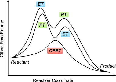
Homogeneous redox catalysis typically involves multiple proton–electron transfers in a single turnover, a process known as the stepwise proton‐coupled electron transfer (PCET) pathway (Scheme 1).^[^ 62, 63, 64, 65 ^]^ This pathway comprises two main processes, namely ET followed by PT (ETPT) or vice versa (PTET). Either of these processes may encounter a kinetically unfavorable route because of the formation of short‐lived charged intermediates. In contrast, CPET involves the simultaneous transfer of an electron and a proton within a single reaction step, as opposed to the sequential transfer mentioned above (Scheme 1).^[^ 66, 67, 68 ^]^ This process may offer advantages over sequential ETPT or PTET, as it circumvents the formation of high‐energy intermediates and potentially reduces the activation energy. Consequently, effective methods of rendering redox reactions more efficient are highly sought after.
Schematic Gibbs free energy diagrams of proton transfer followed by electron transfer (PTET), electron transfer followed by proton transfer (ETPT), and concerted proton–electron transfer (CPET).
For a stepwise ETPT or PTET pathway, either the PT or ET can be the turnover‐limiting step (TLS). RM and PR utilization are expected to lower the kinetic energy barrier of ET and PT, respectively. If the activation energy of the TLS is notably lowered with the assistance of RMs or PRs, the reaction mechanism may change from ETPT or PTET to CPET because of the TLS change. EPTMs are capable of shuttling both PT and ET, and a CPET pathway becomes possible if PT and ET are concertedly promoted and occur. Collectively, RMs, PRs, and EPTMs have been utilized in molecular catalysis to promote kinetically favorable pathways and enhance catalytic activity.
EPTMs in Molecular Catalysis
2.1
EPTMs are molecules that promote the concurrent movement of electrons and protons during chemical reactions (Scheme 2a).^[^ 42, 43, 44 ^]^ Acting as transporters, these species enable a more efficient and often lower‐energy transfer of electrons and protons compared with scenarios where these transfers occur independently, such as ETPT or PTET pathways. Specifically, EPTMs may encourage the reaction to follow the CPET pathway with optimal energy efficiency, thereby enhancing reaction kinetics (i.e., increasing k cat and TOF_max_).^[^ 44, 45 ^]^ Thus, one can circumvent energetic reaction pathways and thereby maintain catalyst longevity to achieve reasonable turnover numbers (TONs). For a multiple proton–electron transfer reaction, different selectivities can be achieved with the use of EPTMs, as the product distribution can presumably be modulated through control of PT and ET.^[^ 46, 69 ^]^
Schematic showing a) electron–proton transfer mediators (EPTMs), b) redox mediators (RMs), and c) proton relays (PRs) in molecular catalysis, as well as the utilization of d) solely EPTMs or RMs, e) self‐independent EPTMs or RMs with the molecular catalyst, and f) EPTMs or RMs covalently anchored to the molecular catalyst.
RMs in Molecular Catalysis
2.2
RMs are molecules that facilitate outer‐sphere ET between a catalyst and an electrode, changing the ET in the molecular catalyst from a heterogeneous to a homogeneous process (Scheme 2b).^[^ 45, 46 ^]^ The thus enhanced regeneration of catalytically active species results in improved catalytic performance.^[^ 57, 58 ^]^ RMs (or EPTMs) can also refer to redox‐active units in the SCS that facilitate intramolecular ET (or CPET) between them and substrate‐bound active sites and often enhance the efficiency of redox reactions.^[^ 70, 71 ^]^ Beyond this context, ligands containing RMs (or EPTMs) in the PCS can potentially act as redox reservoirs and participate in ET (or CPET) alongside the metal center in molecular metal complexes, in which case they are termed “redox non‐innocent ligands.”^[^ 72, 73, 74, 75, 76 ^]^ Importantly, ligand–metal cooperative redox events can help delocalize electron density and stabilize transient intermediates with high‐energy oxidizing/reducing states.
PRs in Molecular Catalysis
2.3
In biological frameworks such as enzymes, PRs correspond to molecules within a system where protons are effectively transferred from a distant location to the reaction center through a chain of hydrogen bonds.^[^ 77, 78 ^]^ This process relays the proton along the sequence, facilitating a (bio)chemical reaction by enabling rapid proton movement over distances exceeding the limitations of a single hydrogen bond. From the perspective of molecular catalysts, PRs are substituents located within a catalyst, generally dangling in the SCS and oriented toward the catalytically active center (Scheme 2c).^[^ 47, 48, 49, 52 ^]^ These substituents function as proton conduits, facilitating swift and targeted PT to/from the bound substrate and thereby promoting PT during reactions.
A PR should be carefully designed to ensure that it plays the expected role in a redox reaction. For a molecular catalyst, the dangling PR should have an appropriate pK a matching that of the catalyst resting state. Balanced proton donation and acceptance, based on the reaction environment, must be considered, as the pK a values of PRs and catalytically active centers are influenced by the medium.^[^ 47, 64, 79 ^]^ Furthermore, PRs should be positioned close to the catalytic center for effective PT. A well‐designed hydrogen‐bonded network ensures directional and efficient proton flow throughout the reaction. Importantly, the PR should resist oxidation/reduction and degradation over multiple catalytic cycles. To implement this concept in molecular catalysts, substituents containing acidic (i.e., carboxyl and sulfo) or basic (i.e., amino and pyridyl) groups have been introduced into the SCSs of metal complexes to promote the water oxidation.^[^ 50 ^]^
Strategies for Implementing Mediators and PRs in Molecular Catalysis
2.4
Homogeneous redox catalysis with EPTMs or RMs generally relies on the utilization of i) solely EPTMs or RMs (Scheme 2d), ii) self‐dependent EPTMs or RMs combined with the molecular catalyst (Scheme 2e), or iii) EPTMs or RMs covalently anchored to the molecular catalyst (Scheme 2f).^[^ 42, 44, 80, 81 ^]^ In case (i), EPTMs or RMs are themselves regarded as catalysts and can directly promote the conversion of reactants into products in the absence of a molecular co‐catalyst. In case (ii), the reaction mixture is commonly supplemented with a superstoichiometric quantity of mediators to ensure that the reaction kinetics are not limited by the mass transfer rate of mediators.^[^ 82 ^]^ Although this strategy is convenient and easy to realize, the solubility of a mediator depends on its identity and the reaction medium, and excess mediators in the solution can hinder in situ experiments aimed at investigating the reaction intermediates.^[^ 83, 84 ^]^
The coupling of a mediator with a molecular catalyst via covalent linkages is another strategy for engaging the mediator to shuttle protons and electrons during the redox process. Conceptually, this approach is similar to PR installation in the SCS of molecular catalysts.^[^ 47, 48, 49, 52 ^]^ A prominent advantage of mediator‐integrated molecular catalysts is that intramolecular PT and/or ET are presumably more effective than the intermolecular processes promoted by exogenous mediators. Moreover, the absence of superstoichiometric exogenous mediators eliminates potential interference during the in situ monitoring of reaction intermediates, thereby facilitating the elucidation of reaction mechanisms. Despite the above merits, mediator‐containing hybrid catalysts may be challenging to synthesize and design.
The redox potential of the mediator and the distance between the catalytically active center and mediator (similar to the PR case) may require fine‐tuning to optimize PT and/or ET kinetics. For example, it may be necessary to locate tethered mediators or PRs near the catalytic center in an appropriate orientation to facilitate intramolecular ET and PT.^[^ 48, 85, 86 ^]^ The stabilities of mediators or PRs as substituents in molecular catalysts also require a comprehensive examination to confirm that the observed enhancement in redox catalysis is not due to heterogeneous catalysts (e.g., nanoparticles or metal oxides) generated by catalyst degradation.^[^ 87, 88 ^]^ Thus, in comparison with the use of exogenous mediators, rational catalyst design regarding catalyst–mediator dyads remains challenging.
Molecular Catalysis: Definition and Metrics
3
Performance assessments from kinetic and thermodynamic perspectives are important for understanding and enhancing the efficiencies of molecular catalysts.^[^ 50, 61, 89 ^]^ The parameters commonly used to evaluate molecular catalysts include the Faradaic efficiency (FE), quantum yield (QY) or apparent quantum yield (AQY), TON, TOF_max_, and η, which are discussed below.
FE
3.1
FE is a direct measure of the efficacy of an electrochemical reaction, corresponding to the proportion of the total cumulative charge (Q tot, C) used to generate the desired product (Q prod, C) (Equation 1).^[^ 90, 91 ^]^ The determination of Q prod (C) requires knowing the quantity of the obtained product (N prod, mol), which can be determined using different instrumental techniques. Consequently, FE can be obtained by estimating Q prod using Faraday's law of electrolysis (Equation 2, where n c is the number of electrons per turnover, e.g., four for O_2_/H_2_O, and F is Faraday's constant, i.e., 96485 C mol^−1^).
QY or AQY
3.2
In photocatalysis, QY denotes the proportion of absorbed photons (N pa) that transform a substrate molecule into the target product (N prod) during a light‐driven chemical reaction (Equation 3).^[^ 92 ^]^ Depending on the wavelength of the employed light, QY can be estimated using different chemical and physical actinometries.^[^ 92, 93, 94, 95 ^]^ Owing to the difficulties in quantifying the photons absorbed by the photocatalyst, the QY associated with photocatalysis can be derived by replacing the measured N pa with the estimated number of incident photons, in which case the resulting parameter is denoted as AQY (Equation 4).^[^ 89, 96, 97 ^]^ In Equation (4), N A is Avogadro's constant (6.02 × 10^23^ mol^−1^), h is Planck's constant (6.626 × 10^−34^ J s^−1^), c is the speed of light in vacuum (3 × 10^8^ m s^−1^), P is the power density of the monochromatic incident light (W m^−2^), S is the irradiation area (m^2^), λ i is the wavelength of the incident monochromatic light, and t is the duration of the exposure to incident light (s)
In the ideal scenario (Φ QY(AQY) = 1), every absorbed photon results in the formation of one molecule of the desired product. However, Φ QY(AQY) is typically less than unity because of light scattering, reflection, and other non‐productive processes.^[^ 98, 99 ^]^ Additionally, Φ QY(AQY) values markedly exceeding unity generally imply radical chain reactions.^[^ 100 ^]^ Overall, Φ QY(AQY) represents the effectiveness of the photocatalytic process, corresponding to the number of reaction turnovers triggered by each absorbed photon.
TON
3.3
In homogeneous catalysis, the TON is defined as the number of substrate molecules converted into product molecules (N prod) per unit of catalyst (N cat), as shown in Equation (5).^[^ 101, 102, 103 ^]^ Given that time is not factored into the calculation, the TON is a dimensionless metric and may therefore not accurately reflect the kinetic properties of the catalyst. For example, a catalyst with a slow but steady activity can achieve a high TON. However, the long‐term durability of a catalyst does not necessarily imply that it exhibits optimal kinetic performance.^[^ 50, 101, 102 ^]^
TOF
3.4
The TOF represents the TON relative to the reaction duration (t), i.e., the number of substrate molecules converted into product molecules per catalyst molecule within a given timeframe (Equation 6).^[^ 101, 102, 103 ^]^ The TOF is a uniform criterion for assessing catalyst kinetics, enabling the reactivity evaluations of various dissolved molecular catalysts under different reaction conditions. However, this metric provides limited information regarding catalyst durability and should therefore be used with caution. Notably, catalysts exhibiting higher TOFs may degrade within a short timeframe and, therefore, exhibit low long‐term performance and be poorly suited for practical applications.^[^ 50, 101, 102 ^]^
For homogeneous electrocatalysts, the TOF_max_ can be calculated from cyclic voltammetry (CV) data (Equations 7 and 8):^[^ 101, 104 ^]^
In Equation (7), i c is the catalytic current (plateau‐shaped wave or scan rate‐independent current (A)),^[^ 104 ^]^ A is the surface area of the working electrode (cm^2^), C cat is the catalyst concentration (m), D cat is the diffusion coefficient of the catalyst (cm^2^ s^−1^), and k obs is the observed rate constant (s^−1^) identical to the TOF_max_ value.^[^ 101, 105 ^]^ Equation (8) can be considered a variant of Equation (7) and is commonly used when the measurement of A or D cat is experimentally challenging. Three parameters of Equation (8) need to be independently measured, namely the peak current of the catalyst (i p, A), the electron transfer number of the catalyst in the absence of the substrate (n p), and the scan rate (v, V s^−1^).
In instances where an ideal S‐shaped CV curve cannot be obtained because of side phenomena such as substrate depletion, catalyst deactivation, and product inhibition, foot‐of‐the‐wave analysis (FOWA) offers an alternative for the determination of TOF_max_ (Equation 9).^[^ 101, 104, 106 ^]^ FOWA primarily targets the “foot” region of the catalytic wave, a zone where intrinsic kinetic behavior is exhibited with minimal interference from side effects. In Equation (9), E CAT is the catalytic potential, which is discussed in Section 3.5.
η
3.5
η describes the additional energy beyond the thermodynamic equilibrium potential required for a reaction to occur at a measurable rate under particular conditions.^[^ 61, 107 ^]^ For molecular electrocatalysts, η can be determined as the difference between the thermodynamic potential (E rxn) and catalytic potential (E CAT) associated with the analyzed reaction (Equation 10).^[^ 50, 61, 107 ^]^ η reflects the influence of the solvent and reaction conditions on the thermodynamic properties of the electrochemical reaction (E rxn), as well as the catalytic potential of molecular catalysts (E CAT).
Using η as a normalized metric, one can benchmark catalyst performances across different studies, even if the reaction conditions are not identical. However, the η values reported in different studies should be compared with caution, as various potentials have been employed to represent E CAT, including the half‐wave potential of the catalyst (E 1/2), potential at the half‐maximum of i c (E cat/2), potential corresponding to the emergence of i c (E onset), anodic potential of the irreversible wave related to the catalyst (E a), and applied potential of controlled‐potential electrolysis (E CPE). Depending on the choice of E CAT, η may exhibit discrepancies of more than 100 mV.^[^ 107 ^]^ Therefore, when comparing the η values reported in different studies, one should ascertain whether the definition of η is consistent across these studies.
Log(TOF)−η Analysis and Catalytic Tafel Plot
3.6
The value of η required to achieve the TOF demonstrated by a specific catalyst is a crucial measure of its efficacy. An LFER can be constructed to examine the proportional influence of η on log(TOF). Given that the TOF and η are considered standardized metrics, LFER analysis can independently benchmark the effectiveness of catalysts, assessing catalyst performance through a 2D approach (Figure 1a). For catalysts positioned in the upper left corner of Figure 1a, a minimal η is required to achieve a high catalytic rate, which is characteristic of high‐performance catalysts.
a) Representative log[turnover frequency (TOF)]−overpotential (η) correlation for different series of molecular catalysts (i.e., red and blue dots). b) Representative catalytic Tafel plot for different molecular catalysts.
LFER analysis often reveals a trade‐off relationship between kinetics and thermodynamics for homogeneous catalysts. A higher TOF generally results in a higher η, and vice versa.^[^ 61, 107, 108 ^]^ Nonetheless, the strategic design of catalysts in the SCS and manipulation of reaction conditions may help circumvent this conventional scaling relationship.^[^ 109, 110, 111 ^]^ Importantly, the same series of catalysts is expected to align with the same linear trend of log(TOF)/η because the catalysts possess identical TLSs.^[^ 112, 113 ^]^ Thus, caution should be exercised when benchmarking catalyst performance exclusively based on LFER analysis without insights into the reaction mechanism, as these catalysts may feature different TLSs.^[^ 114, 115 ^]^
In addition, catalytic Tafel plots have emerged as an alternative for describing the relationship between catalytic activity and energetic driving force in molecular electrocatalysis.^[^ 60, 61, 116 ^]^ Unlike traditional heterogeneous Tafel analysis, which relates current density to applied overpotential (η app), (homogeneous) catalytic Tafel plots describe how the observed TOF of molecular catalysts depends on η app (Figure 1b). This method provides a unified way of benchmarking catalysts that may differ in structure, mechanism, and reaction conditions.
The mathematic basis of Tafel plot analysis is shown in Equation (11), where TOF_max_ is η app−independent TOF. By extrapolating the log(TOF) curve to η app = 0 V, one can ascertain the intrinsic catalytic activity of a molecular catalyst, TOF_0_ (Figure 1b). At a low driving force, the catalytic rate increases exponentially with η app, reflecting the fraction of catalyst molecules activated through reduction or oxidation. In this regime, the slope of the plot approximates the Nernstian value, signifying that ET governs the population of the active catalyst. As η app is increased further, the plot transitions into a plateau region where the catalyst is almost completely present in its active redox state. Here, the rate becomes independent of ET and approaches TOF_max_, which corresponds to the k cat of the TLS (Equation 12). The resulting curve is sigmoidal in shape, capturing the potential‐dependent activation and rate‐limiting chemical step.
Applications of EPTMs, RMs, and PRs in Molecular Catalysis
4
In this section, the benefits of using EPTMs, RMs, and PRs in the molecular redox catalyst–promoted transformations of small energy‐related molecules and organic reactions are discussed from the perspectives of kinetics, thermodynamics, and selectivity. The involvement of these co‐catalysts in the reaction mechanism is also discussed.
CO2 Reduction Reaction (CO2RR)
4.1
EPTMs in the Molecular Catalyst–Promoted CO2RR
4.1.1
Chang et al. (2020) used nicotinamide adenine dinucleotide (NAD^+^/NADH) analogs (Figure 2, EPTM‐1–7) as EPTMs with Fe tetraphenylporphyrin (Fe(TPP), Fe‐1) as a catalyst to promote the electrochemical CO_2_RR.^[^ 117 ^]^ In the presence of phenol (PhOH) as a proton source, the ECEC (E: electron transfer step, C: chemical step) behavior of EPTM‐1–3 was revealed by CV studies (Figure 2, EPTM‐1/EPTM‐1′). The importance of a 2H^+^/2e^−^ mediator in electrochemical CO_2_RR was evidenced by catalytic performance comparison, with EPTM‐1–3 being most effective (Table 1). EPTM‐4 and EPTM‐5 were unable to mediate a 2H^+^/2e^−^ process, affording TOFs lower than those of the other EPTMs by around one order of magnitude. EPTM‐6 and EPTM‐7 served as proton‐ and electron‐only mediators, respectively, and their effectiveness in the electrochemical CO_2_RR was lower than that of EPTM‐1–3. This outcome suggested the crucial role of amide and pyridine substituents in the EPTM. The incorporation of EPTM‐1–7 into the system did not compromise the selectivity for CO, which remained the primary product, and had only a minimal effect on the FE (Table 1). The synergy between Fe‐1 and these NADH‐type mediators was further assessed using a catalytic Tafel plot, which revealed that at η ≥ 700 mV, the catalytic activity (i.e., TOF_max_) exceeded that observed for Fe‐1 alone ≈15‐fold (Table 1, entry 1 vs entries 2−4 and Figure 3).
*CO2 reduction reaction (CO2RR) catalyzed by Fe‐1 in the presence of different mediators (EPTM‐n, n = 1–7). Reproduced with permission.[
117
] Copyright 2020, American Chemical Society.*
**Table 1: Performances of Fe‐1 and Fe‐1/EPTM‐n (n = 1–7) systems in the electrochemical CO2RR.[
117
]**
*Catalytic Tafel plots obtained for Fe‐1 alone and upon the addition of 1 equiv. EPTM‐n ( n = 1–7). Reproduced with permission.[
117
] Copyright 2020, American Chemical Society.*
Mougel et al. reported a notable example highlighting the importance of mediator design, using a Mn complex to promote the electrochemical CO_2_RR (Figure 4, Mn‐1 and EPTM‐8).^[^ 118 ^]^ The bond dissociation free energy (BDFE) matching between the catalyst (Mn^I^‐H, 67.3–65.8 kcal mol^−1^) and EPTM ([Fe‐S]H, 63.5 kcal mol^−1^) was pivotal for optimizing reaction selectivity (FE_HCOOH_: 92%) and TOF (∼20 s^−1^). When the BDFE of the EPTM exceeded that of Mn^I^‐H, CO was the only product (Table 2). This observation implies that [Mn^I^‐H], which could only be formed under the conditions of BDFE_cat‐H_ > BDFE_EPTM‐H_, served as the key species for the selective production of formate from CO_2_RR via the hydride transfer pathway.
*Mn complex (Mn‐1) and EPTM‐8 used to investigate the electrochemical CO2RR.[
118
]*
**Table 2: Performances of Mn‐1 and Mn‐1/EPTM‐8 systems in the electrochemical CO2RR.[
118
]**
A plausible catalytic cycle is depicted in Figure 5. A single‐electron reduction and PT at a terminal Fe‐S‐Ph unit afford the activated form of EPTM‐8 ([Fe‐S]H), and CPET between [Fe‐S]H and [Mn^0^‐cat] yields [Mn^I^‐H] and suppresses the formation of an off‐cycle dimeric Mn species. Subsequently, Mn^I^‐H is further reduced to [Mn^0^‐H], which then mediates the transfer of hydride to CO_2_, resulting in the production of HCOOH. This reductive pathway to [Mn^0^H] is thermodynamically more favorable than the direct formation of Mn^I^‐H via Mn‐1 protonation in the absence of EPTM‐8. This work highlights the effectiveness of EPTM‐assisted strategies in advancing the electrochemical CO_2_RR.
*Proposed mechanism for EPTM‐8‐mediated Mn‐1 formation and subsequent hydride transfer to CO2.[
118
] Copyright 2022, Springer Nature.*
RMs in the Molecular Catalyst–Promoted CO2RR
4.1.2
Machan et al. presented a cooperative electrocatalytic method for the conversion of CO_2_ into CO using a molecular Cr complex (Cr‐1) and dibenzothiophene‐5,5‐dioxide (RM‐1) as an RM (Figure 6).^[^ 119 ^]^ The reduction potential of RM‐1 is important for the success of this co‐catalysis, as it must be lower than that of Cr‐1. TOFs of up to 65 s^−1^ were achieved at η = 410 mV using PhOH as a proton donor (Table 3). In control experiments, no CO production was detected, and no coproducts (i.e., CO or CO_3_ ^2−^) were observed for either Cr‐1 or RM‐1 alone. The inner‐sphere ET from the bound RM‐1 to the di‐CO_2_ adduct of Cr‐1, ([Cr(CO_2_CO_2_(RM‐1)]^2−^), was facilitated by through‐space electronic conjugation (TSEC), helping RM‐1 effectively mediate the electrocatalytic CO_2_RR.
*Cr complexes (Cr‐n, n = 1–4) and RMs (RM‐n, n = 1–5) used to investigate the electrochemical CO2RR.[
120 , 121 , 122
]*
**Table 3: Performances of Cr‐n ( n = 1–4) and Cr‐n ( n = 1–4)/RM‐n ( n = 1–5) systems in the electrochemical CO2RR.[
120 , 121 , 122
]**
In 2022, the same group rationally designed catalysts (Cr‐2) and RMs (RM‐2–4) to circumvent the trade‐off between the TOF and η through the influence of TSEC and pancake bonding (PB) interactions between the Cr catalysts and RMs (Figures 6 and 7).^[^ 120 ^]^ Figure 7 shows the catalytic cycle proposed for the electrochemical CO_2_RR catalyzed by Cr‐1 and Cr‐2 with RM‐1–4. The formation of iv from i was presumably the thermodynamically favored process. In the presence of RMs, the single‐electron‐reduced RM associated with species iv to generate an important intermediate, v. The C–OH bond cleavage of v was reported as the TLS, and [Cr–CO]^−^ (vi) was formed concurrently with the release of the neutral RM and H_2_O upon the incorporation of a second equivalent proton. Following the liberation of CO, vi transformed into a monoanionic four‐coordinate neutral Cr species (ii), and the catalytic cycle was completed. The impact of PB interactions became more prominent with the increasing number of phenyl groups in the RM. For example, a quantitative selectivity for CO at η = 280 mV along with a TOF of 194 s^−1^ was achieved using Cr‐2, 2,8‐diphenyldibenzothiophene‐5,5‐dioxide (RM‐3), and PhOH as the proton source (Table 3). This result indicates that the electron‐donating tert‐butyl substituents on the backbone bipyridine (bpy) motif improved the kinetics of the CO_2_RR.
*Catalytic cycle proposed for the electrochemical CO2RR promoted by Cr catalysts and RMs. Reproduced under terms of the CC‐BY‐NC license.[
120
] Copyright 2022, Royal Society of Chemistry.*
Subsequently, a catalyst bearing a phenanthroline (phen) backbone (Figure 6, Cr‐3) was prepared to enhance PB interactions and more efficiently promote the CO_2_RR. The compensatory relationship between PB and dispersion interactions affected the formation of Cr−RM adducts. Consequently, a TOF of 126 s^−1^ was achieved at η = 280 mV in the presence of RM‐3 and PhOH (Table 3).^[^ 121 ^]^ The same group also demonstrated that the E CAT of the CO_2_RR was correlated with the E 1/2 of the RM (RM‐1 or RM‐5), and optimized performance was achieved when the E 1/2 of the RM matched that of the Cr catalyst (Table 3).^[^ 122 ^]^ This finding implies that the redox potentials of the catalysts and RMs must be carefully considered in electrocatalysis.
Figure 6 shows the log(TOF)−η plots of these Cr CO_2_RR catalysts with different RMs, revealing the dependence of the catalytic effectiveness on catalyst–RM cooperation. For example, Cr‐3 and Cr‐4 showed remarkable reaction kinetics in the presence of RM‐5 and PhOH, with η ≈ 0.1 V (data points: 2‐F, 3‐F, and 4‐F). The integration of RM‐3 with Cr‐1–3 using PhOH as the proton source gave comparable TOFs, and the reactions were operated at η ≈ 0.3 V (Table 3, entries 1‐E, 2‐E, and 3‐E). The catalytic turnover of the co‐catalytic systems exceeded those of catalyst‐only systems by several orders of magnitude at similar η values (Figure 8, points 1‐A, 2‐A, 3‐A, and 4‐A). These results demonstrate that the interplay between RMs and catalysts is crucial for enhancing the efficacy of redox catalysis, suggesting that the consideration of tethered substituents and redox potentials is necessary to optimize molecular RMs.
*Results of linear free‐energy relationship (LFER) analysis obtained for Cr‐n ( n = 1–4) and Cr‐n ( n = 1–4)/RM‐n ( n = 1–5) systems used to promote the electrochemical CO2RR.[
120 , 121 , 122
]*
Warren et al. (2024) used an Fe(TPP)–pyrene complex to promote the electrocatalytic CO_2_RR (Figure 9, Fe‐2).^[^ 123 ^]^ Unlike Fe‐3, Fe‐2 contains a redox‐active pyrenyl group in the TPP framework. This design enabled intramolecular ET from the pyrenyl group to the Fe metal center under electrochemical conditions and resulted in CO_2_‐to‐CO catalytic turnovers exceeding those of Fe‐1 and Fe‐3 10‐ to 100‐fold (Table 4 and Figure 10a).^[^ 123 ^]^ The intramolecular ET rate was influenced by the proximity of the RM to the catalytic center. This insight suggests that caution must be exercised in the design of pendant RMs for the SCS of molecular catalysts.
*Fe(TPP) complexes, Fe‐n (n = 1–14), used for the electrochemical CO2RR.[
123 , 124 , 125 , 126
]*
**Table 4: TOF and η values obtained for the electrochemical CO2RR catalyzed by Fe(TPP) complexes Fe‐n ( n = 1–14) in N,N‐dimethylformamide (DMF).[
123 , 124 , 125 , 126
]**
*Tafel plots constructed for the electrochemical CO2RR catalyzed by different Fe(TPP) complexes: a) Fe‐1–3, b) Fe‐1 and Fe‐4–8, and c) Fe‐1, and Fe‐9–12. Reproduced with permission.[
123 , 124 , 125
] Copyright 2024, American Chemical Society.*
PRs in Molecular Catalyst–Promoted CO2RR
4.1.3
The CO_2_RR can also be promoted using catalysts with appropriately positioned PRs. Warren et al. developed Fe(TPP) catalysts bearing different numbers of ortho‐hydroxyl groups on their phenyl rings (Figure 9, Fe‐4–8).^[^ 124 ^]^ These groups increased the concentration of H^+^ around the Fe metal center, thereby accelerating the reaction, as evidenced by the increased catalytic currents and TOFs (Table 4). The corresponding catalytic Tafel plots showed that cis‐ and trans‐Fe(TPP)(OH)4 (Fe‐5 and Fe‐6) exhibited higher activities than the other Fe(TPP)(OH)* n
- catalysts (Figure 10b, n = 0 (Fe‐1), 2 (Fe‐4), 6 (Fe‐7), and 8 (Fe‐8)). The volcano‐type correlation between the CO_2_RR activity and the number of attached hydroxyl groups revealed that the trade‐off between the TOF and η is an important factor to consider in catalyst design. The concentration of exogenous Brønsted acids (i.e., PhOH) and solvent type may influence the stability of the Fe–CO_2_ adduct and PT from the relay hydroxyl groups via hydrogen bonding. This influence should be further investigated to optimize ligand design and clarify the effect of the reaction medium on the outcome.
For Fe(TPP) catalysts bearing 2‐hydroxyphenyl groups with different electronic properties (Figure 9, Fe‐9–12), k cat was correlated with catalyst pK a.^[^ 125 ^]^ For the catalyst with the lowest pK a (Fe‐11), intramolecular PT was preferred. Instead, for the catalyst with the highest pK a (Fe‐12), the stabilization of the reduced [Fe^I^–CO_2_] intermediate through hydrogen bonding played a crucial role, and intermolecular PT from PhOH was more favorable. The observed primary kinetic isotope effect indicated that protonation was the TLS for Fe‐9–12. The corresponding catalytic Tafel plot demonstrated that Fe‐12, bearing an electron‐donating methoxy substituent at the para position, afforded the fastest catalytic turnover (Figure 10c), which was attributed to the facile reprotonation of the internal hydroxyphenyl group of the [Fe^I^–CO_2_H] intermediate. Fe‐13, featuring a catechol unit ancillary to the TPP motif, exhibited a 1.7‐fold higher TOF than Fe‐14 under the same reaction conditions (Table 4 and Figure 10c).^[^ 126 ^]^ Density functional theory analysis indicated that internal hydrogen bonding involving the catechol group of Fe‐13 enhanced the stability of the [Fe^I^–CO_2_H] intermediate, thereby resulting in an internal PT more effective than that observed for Fe‐14.
Machan et al. (2024) reported a collaboration between Cr catalysts (Figure 11, Cr‐5 and Cr‐6) and external Lewis acids (PhOH and triethylammonium hexafluorophosphate, TEAHPF_6_), revealing that the reaction rate was highest for Cr‐6/TEAHPF_6_ (Table 5).^[^ 127 ^]^ The corresponding log(TOF)−E cat/2 analysis revealed that Cr‐6/TEAHPF_6_ demonstrated the best thermodynamic and kinetic performances for the electrochemical CO_2_RR (Figure 12). The inverse relationship observed for this system was ascribed to the cationic acid stabilizing the negatively charged reaction intermediates with the assistance of the suspended methoxy group, which rendered the deprotonation of the [Cr–CO_2_H]^−^ intermediate less energetic.
*Cr complexes (Cr‐5 and Cr‐6) used to electrochemically catalyze the CO2RR.[
127
]*
**Table 5: Performances of Cr‐n (n = 1–3, 5, and 6) catalysts in different proton source systems for the electrochemical CO2RR.[
127
]**
*Log(TOF)–E cat/2 analysis of different Cr catalysts. Reproduced with permission.[
127
] Copyright 2023, Royal Society of Chemistry.*
Oxygen Reduction Reaction (ORR)
4.2
EPTMs in the Molecular Catalyst–Promoted ORR
4.2.1
Mondal et al. (2023) synthesized a mononuclear Co complex (Figure 13, Co‐2) bearing a salophen‐type Schiff‐base ligand (Sal) and covalently linked hydroquinone (H_2_Q).^[^ 128 ^]^ Unlike the bare (Sal)Co complex (Figure 13, Co‐1), which favored the 2H^+^/2e^−^ ORR affording H_2_O_2_, the complex with the appended H_2_Q units favored the 4H^+^/4e^−^ ORR affording H_2_O (Table 6). CV and differential pulse voltammetry were used to examine the benzoquinone (BQ)/H_2_Q and Co^III/II^ redox couples, along with the E onset of the catalytic ORR. Co‐1 and Co‐2 exhibited a catalytic wave ≈−1.1 V vs ferrocene (Fc)^+/0^; however, Co‐2 displayed a markedly higher current than Co‐1 under similar conditions (≈106 vs 45.8 µA). The higher catalytic current and different selectivities (Table 6) suggest that the attached H_2_Q moieties led to a change in the reaction mechanism.
*Co catalysts used for the oxygen reduction reaction (ORR): (a) Co‐1 and (b) Co‐2.[
128
]*
**Table 6: Performances of Co‐1 and Co‐2 systems in the (electro)chemical ORR.[
128
]**
At low and high acid concentrations (10 and 300 mM acetic acid, respectively), Co‐2 exhibited a reactivity comparable with that of Co‐1 in the presence of 10 and 2 equiv. exogenous BQ, respectively. Changes in acid concentration, which influence the reactivity of Co‐1 and Co‐2, are indicative of a consequential change in the TLS. At a low acid concentration, the protonation of Co^III^−O_2_H, which liberates H_2_O_2_, could be the TLS (Figure 14a); while the transfer of 2H^+^/1e^−^ to (Sal^H2Q^)Co−O_2_ ^•^ is proposed to be TLS for Co‐2 (Figure 14b), as suggested by the slope of 92 mV dec^−1^ for the corresponding E cat/2 vs log[acetic acid (AcOH)] plot. At a high acid concentration (i.e., AcOH ≥ 100 mM), the step of cobalt superoxide formation serves as the TLS for both Co‐1 and Co‐2.
*Catalytic cycles of the ORR promoted by (a) Co‐1 and (b) Co‐2. Reproduced with permission.[
128
] Copyright 2023, American Chemical Society.*
The introduction of exogenous EPTMs can also increase the ORR activity. Stahl et al. accelerated the ORR using Co‐1 and BQ (EPTM‐10, Figure 15). Controlled‐potential electrolysis (CPE) data showed that the current density of the Co‐1 + H_2_Q (EPTM‐9) system (0.54 mA cm^−2^) was double that of the Co‐1 system (0.27 mA cm^−2^).^[^ 129 ^]^ The ORR selectivity changed from 100% H_2_O_2_ to 60% H_2_O upon the use of EPTM‐9 as the exogenous EPTM with Co‐1, a mononuclear Co(sal)‐type catalyst (catalysts of this type generally mediate the ORR via the 2H^+^/2e^−^ pathway).^[^ 114 ^]^ The same group also demonstrated that under electrochemical ORR conditions, H_2_Q (2 equiv.) reacts with the Co(sal)–O_2_ adduct via hydrogen‐atom transfer (HAT) followed by PCET,^[^ 130 ^]^ which leads to the formation of H_2_O based on the rapid reduction of the formed H_2_O_2_ via an energetically favorable pathway (i.e., O_2_ → H_2_O_2_ → H_2_O).
*Electrochemical ORR catalyzed by Co‐1 in the presence of EPTM‐9 (0−40 mm).[
129
] Conditions: 1.0 mm Co‐1, 0.3 m acetic acid (AcOH), 0.1 m NBu4PF6, 1 atm O2, 40 mL DMF. Working electrode: reticulated vitreous carbon. Potential: −760 mV vs Fc+/0.*
RMs in the Molecular Catalyst–Promoted ORR
4.2.2
Kadish et al. (2014) prepared Co(TPP) complexes with different numbers of Fc groups at the meso positions of TPP and examined their abilities to promote the electrochemical ORR (Figure 16, Co‐3–6).^[^ 131 ^]^ The redox events of these complexes were examined using UV–vis spectroelectrochemistry, and the covalently linked Fc groups were found to contribute to the ligand‐centered redox event. However, the authors did not determine whether these redox events are involved in the TLS or probe the impact of Fc substituents on the catalytic efficiency. Electrochemical studies revealed that the incorporation of the Fc substituent onto TPP caused an anodic shift in the reduction potential of Co(III)/(II), E pc. A selectivity study revealed that Co‐3–5 exclusively afforded H_2_O_2_, whereas Co‐6 afforded 40% H_2_O (Table 7). The steric hindrance induced by the Fc groups prevented the formation of dimeric Co species, thereby accounting for the observed selectivity.
*Co(TPP) complexes, Co‐n ( n = 3–6), used to promote the electrochemical ORR.[
131
]*
**Table 7: Performances of Co‐n ( n = 3–6) systems in the electrochemical ORR.[
131
]**
PRs in the Molecular Catalyst–Promoted ORR
4.2.3
Biswas et al. (2020) synthesized a Cu(II) complex bearing a monoanionic pentadentate amidate ligand (dpaq) for use as an ORR electrocatalyst (Figure 17, Cu‐1).^[^ 132 ^]^ When protonated, the carboxamido group of dpaq functioned as a PR, whereas the quinoline‐based moiety contributed the redox equivalent required for the conversion of Cu‐1 and O_2_ into a (dpaqH)Cu(II)‐hydroperoxo species via internal 2H^+^/2e^−^ transfer. The number of electrons transferred (n c) in the ORR was calculated as 3.8 by rotating ring disk voltammetry, and chronoamperometric measurements revealed that the ORR proceeded via a stepwise (2e^−^ + 2e^−^) reduction pathway.
*Electrochemical ORR catalyzed by Cu‐1.[
132
]*
Paria et al. prepared Co and Fe complexes featuring metal‐bound bispyridine–dioxime ligands and evaluated their performance as ORR electrocatalysts (Figure 18).^[^ 133, 134, 135 ^]^ Co‐7 selectively afforded H_2_O in an acidic buffer or acetonitrile (MeCN) solution, and the selectivity was strongly influenced by the ligand design and reaction medium.^[^ 133 ^]^ In 0.1 M phosphate buffer, the 4H^+^/4e^−^ pathway became unfavorable with increasing pH. Conversely, Co‐7 retained the selectivity for this pathway under acidic and neutral conditions in 0.1 m acetate buffer (Table 8). LFER analysis revealed that the highest reactivity was achieved at pH 8, with the corresponding TOF reaching ∼5000 s^−1^ at η = 0.7 V (Figure 19). Experimental evidence indicated that the oxime unit in the SCS could act as a PR to deliver a proton. Computational findings suggested that the acetate ion mediated the transfer of a proton from the oxime backbone to the distal oxygen of the Co(III)−OOH species. Consequently, H_2_O was produced in near‐quantitative yields.
*Molecular structures of bispyridine–dioxime complexes (Co‐n ( n = 7–15) and Fe‐n ( n = 16–18)) used as ORR electrocatalysts. S: MeCN.[
133 , 134 , 135
]*
**Table 8: Performances of Co‐7 in the electrochemical ORR at different pH.[
133
]**
*Results of the LFER analysis of the ORR catalyzed by Co‐7 at different pH. General reaction conditions: [catalyst] = 2 mM, [CF3CO2H] = [CF3COO−] = 40 mM, O2‐saturated MeCN solution; [NBu4PF6] = 0.1 M; v = 25 mV s−1.[
133
]*
The same group modified the SCSs of bispyridine–dioxime Co complexes to improve the ORR activity (Figure 18, Co‐7–15).^[^ 135 ^]^ The trade‐off between the TOF and η was circumvented by installing o‐NHMe_2_ ^+^–C_6_H_4_ and o‐OMe–C_6_H_4_ substituents on the bispyridine–dioxime ligand (Figure 18, Co‐8 and Co‐9). The TOFs of Co‐8 and Co‐9 were >1000 and 250 times greater, respectively, than those predicted based on the LFER between log(TOF) and η in a 1:1 CF_3_CO_2_H/CF_3_CO_2_ ^−^ buffer (Table 9 and Figure 20). This outcome suggested that the TLS corresponded to protonation of the Co^III^(O_2_ ^•^) adduct, further indicating that the backbone o‐NHMe_2_ ^+^–C_6_H_4_ and o‐OMe–C_6_H_4_ substituents functioned as PRs and facilitated intramolecular PT to the Co^III^(O_2_ ^•^) adduct. Control experiments revealed that the oxime backbone of the bispyridine–dioxime ligand played a vital role as a proton‐exchange site.^[^ 134, 135 ^]^
**Table 9: Performances of Co‐n ( n = 7–14) systems in the electrochemical ORR.[
135
]**
*Results of the LFER analysis of the ORR catalyzed by Co‐n (n = 7–14). General reaction conditions: [catalyst] = 2 mM, [CF3CO2H] = [CF3COO−] = 40 mM, O2‐saturated MeCN solution; [NBu4PF6] = 0.1 M; ν = 25 mV s−1. Reproduced with permission.[
135
] Copyright 2025, American Chemical Society.*
Analogous Co and Fe complexes lacking an oxime unit did not catalyze the electrochemical ORR (Figure 18, Co‐15, Fe‐16, and Fe‐17). Fe‐17 mediated the chemical ORR in the presence of Cp*_2_Fe as a reductant; however, the corresponding k cat was 300 times lower than that of the oxime unit–containing Fe‐15 (2.47 × 10^2^ vs 6.07 × 10^4^ M^−1^ s^−1^). Overall, these studies provided useful insights into the effects of the appended PRs and reaction media on the performance of mononuclear Co and Fe complexes as ORR (electro)catalysts.
Mayer et al. (2012) evaluated the impact of carboxylate positioning on the kinetics and selectivity of the ORR catalyzed by Fe(TPP)‐based catalysts (Figure 21, Fe‐18 and Fe‐19).^[^ 136 ^]^ Fe‐18 achieved a TOF of 200 s^−1^ and demonstrated a higher selectivity than Fe‐19 (2% vs 9%). These results show that the PR effect observed when the carboxylate group was located at the ortho positions of the phenyl rings was superior to that observed when these groups were located at the para positions. Although the same group later revealed that the higher ORR rate of Fe‐18 was due to its η exceeding that of Fe‐19 under the same conditions, the role of PR in Fe(TPP)‐type catalysts for the ORR is worth exploring.^[^ 137 ^]^ The same series of Fe(TPP) catalysts with different substituents was prepared in the same study to examine the log(TOF)−η correlation for the ORR (e.g., Fe‐20). The identities of the catalyst and reaction media were found to be critical for optimizing catalyst performance, as the value of η is associated with the E CAT and E rxn (Equation 10). For instance, Fe‐20 could achieve a higher ORR rate than Fe‐18 at a lower η.
*Structures of Fe‐n ( n = 1, 18–28) and Co‐n ( n = 16–18) catalysts for the electrochemical ORR.[
136 , 137 , 138 , 139 , 140 , 141
]*
Dey et al. (2018) reported Fe(TPP)‐based ORR electrocatalysts with different amine substituents as pendant bases on the phenyl ring (Figure 21, Fe‐21–23).^[^ 138 ^]^ This catalyst design helped overcome the trade‐off relationship between log(TOF) and η, which was explained from both thermodynamic and kinetic perspectives. Fe‐21–23 achieved ∼100‐fold higher TOFs than that of Fe‐1 at similar η values in DMF solutions (Table 10). Thermodynamically, the intramolecular hydrogen bonding between these pendant bases and the bound hydroperoxide stabilized the reaction intermediates; kinetically, amine protonation facilitated O–O bond cleavage in the bound hydroperoxide, which also increased the selectivity for H_2_O production via the 4H^+^/4e^−^ pathway.
**Table 10: Performances of Fe‐n ( n = 1, 18–28) and Co‐n ( n = 16–18) in the electrochemical ORR.[
136 , 137 , 138 , 139 , 140 , 141
]**
In addition to Fe‐21, a subsequent study reported Fe‐24, which features four N,N‐dibenzylamino substituents at the ortho positions of the phenyl rings (Figure 21).^[^ 139 ^]^ The catalytic efficiencies of Fe‐1, Fe‐21, and Fe‐24 were evaluated in MeCN based on log(TOF)−η relationships (Figure 22). This LFER analysis showed that Fe‐21 and Fe‐24 exhibited TOFs that markedly exceeded the predicted values and that of Fe‐1, confirming that the N,N‐dibenzylamino substituents were capable of mediating heterolytic O−O bond cleavage in the Fe^III^−OOH species. With respect to thermodynamic advantages, Fe‐21 and Fe‐24 catalyzed the ORR at η values ∼100 mV lower than that of Fe‐1. These results highlight that the trade‐off between the reaction rate and driving force can be avoided by utilizing PRs in the ORR.
*Results of the LFER analysis of Fe‐n ( n = 1, 18–24) obtained for the electrochemical ORR performed in DMF (red) and MeCN (blue).[
136 , 137 , 139
]*
In 2022, Goldsmith et al. developed Co^II^ complexes with polydentate N‐donor ligands (Figure 21, Co‐16–18).^[^ 133, 140, 141 ^]^ Unlike the inactive Co‐16, Co‐17 and Co‐18 were electroactive in the ORR and exhibited similar TOFs (Table 10 and Figure 21). This observation indicates that the phenolic components of Co‐17 and Co‐18 facilitated intramolecular PT, thereby enhancing the ORR kinetics. Co‐17, featuring a dangling H_2_Q group, exhibited a higher selectivity for H_2_O than Co‐18, which contained an appended phenol group (Table 10, n c: 3.5 vs 2.2). This finding indicates that the H_2_Q moiety of Co‐16 acted as a 2H^+^/2e^−^ reservoir and influenced the formation of the [Co^III^−OH]^2+^ intermediate, which is proposed to be the product‐determining step. The same group synthesized Fe^II^ and Fe^III^ complexes featuring ligand scaffolds similar to H_2_Q or phenol groups and evaluated their ORR performances (Figure 21, Fe‐25–28).^[^ 141 ^]^ Fe‐25, containing two H_2_Q groups, exhibited a TOF (14.6 s^−1^) several times higher than those of the other Fe catalysts (Table 10 and Figure 23). Additionally, Fe‐25 favored H_2_O over H_2_O_2_ due to the non‐innocence of the covalently linked H_2_Q. This effect was similar to that observed for analogous Co complexes.^[^ 133, 140 ^]^
*Results of the LFER analysis of Fe‐n ( n = 25–28) and Co‐n ( n = 17 and 18) obtained for the electrochemical ORR.[
141
]*
Ghosh et al. prepared a tetradentate mononuclear Cu complex (Figure 24, Cu‐2) and examined its ability to promote the electrochemical ORR and WOR (see Section 4.3 for details).^[^ 142 ^]^ The diimine–dioxime framework provided a labile coordination geometry and served as a PR to enhance the stability of the reduced Cu species. FOWA revealed that Cu‐2 electrochemically catalyzed the ORR or WOR through a bimolecular pathway and generated a µ‐1,2‐peroxo‐dicopper intermediate ([Cu^II^−O_2_−Cu^I^]^−^). Computational studies implied that a mononuclear ([Cu^III^−OH]^+^) was probably formed upon the O−O bond cleavage of [Cu^II^−O_2_−Cu^I^]^−^, which resulted in four‐electron O_2_ reduction. The selective 4H^+^/4e^–^ reduction of O_2_ to H_2_O in the presence of Cu‐2 was observed over an extensive pH range (6.0–12.0), with the highest catalytic efficiency (TOF = 2.1 × 10^5^ s^−1^ at η = 1.10 V) recorded at pH 9.0 (Table 11 and Figure 25).
*Structures of Cu‐n ( n = 2–5) catalysts for the electrochemical ORR and water oxidation.[
142 , 143
]*
**Table 11: Performances of Cu‐n ( n = 2–5) in the electrochemical ORR.[
142 , 143
]
a)**
*Results of the LFER analysis of Cu‐n ( n = 2–5) catalysts used in the electrochemical ORR.[
142 , 143
]*
Two other dinuclear Cu complexes bearing tetradentate N_2_O_2_‐type ligands (Figure 24, Cu‐3 and Cu‐4) also showed bidirectional reactivities in the ORR and WOR.^[^ 143 ^]^ The two peripheral −OH groups on the macrocyclic ligand of Cu‐4 were suggested to function as PRs during catalysis. Therefore, Cu‐4 exhibited a higher catalytic efficiency than Cu‐3 and the control mononuclear Cu(sal) catalyst (Cu‐5), as shown in Table 11 and Figure 23. The ORR study was conducted in aqueous solutions at pH 7–12, and both Cu‐3 and Cu‐4 exhibited the highest TOF at pH 8 (Cu‐3: ∼1000 s^−1^, Cu‐4: ∼3000 s^−1^). No clear correlation between log(TOF) and η for Cu‐3–5 was observed, possibly because pH affected the catalytic pathway (Figure 25).
Water Oxidation Reaction (WOR)
4.3
RMs in the Molecular Catalyst–Promoted WOR
4.3.1
Meyer et al. (1982) reported a dinuclear µ‐oxo‐bridged Ru complex, cis,cis‐[(bpy)2(H_2_O)Ru(µ‐O)Ru(H_2_O)(bpy)2]^4+^ (Figure 26a, Ru‐1) as the first molecular water oxidation catalyst (WOC). This catalyst is also known as the “blue dimer” because of the blue color of its aqueous solutions.^[^ 144, 145 ^]^ At pH 4, Ru‐1 achieved a TON of 13.2 and TOF of 0.0042 s^−1^ based on O_2_ evolution at η = 0.262 V in the presence of ceric ammonium nitrate (CAN) as a sacrificial oxidant.^[^ 15, 145 ^]^ In 2008, the same group investigated the mechanism of the (electro)chemical WOR catalyzed by Ru‐1 in the presence of various Ru mediators (Figure 26a, RM‐6–9).^[^ 146 ^]^ The second‐order rate constants for CAN consumption by catalytically active dimeric intermediates (I: [(bpy)2(HO_2_)Ru^III^ORu^V^(O)(bpy)2]^3+^, II: [(bpy)2(HO_2_)Ru^IV^ORu^IV^(OH)(bpy)2]^4+^) increased 10−30‐fold in the presence of RM‐6–9 (Table 12, k ** I ** and k ** II **), which was attributed to the mediated oxidation of the peroxidic species I and II. These findings suggest that the chemical WOR can be optimized by accelerating inner‐sphere ET using exogenous RMs (Figure 26b). Ru‐1/RM‐7 demonstrated the highest catalytic activity among the other RMs, with η equaling only 230 mV (Figure 27).
*(a) Structures of Ru‐n ( n = 1 and 2)/RM‐n ( n = 6–9) systems used to promote the electrochemical WOR.[
146 , 147
] (b) Proposed catalytic cycle for the chemical WOR promoted by the blue dimer in the presence of RM‐6–9.[
146 , 147
]*
**Table 12: Performances of Ru‐n ( n = 1 and 2)/RM‐n ( n = 6–9) systems in the chemical WOR.[
146
]**
*Results of the LFER analysis of Ru‐1/RM‐n ( n = 6–9) systems used to promote the chemical WOR.[
146
]*
In a subsequent study, Meyer et al. achieved a remarkable rate enhancement using Ru‐2 (Figure 26a) and an indium‐doped tin oxide (ITO) electrode with an immobilized Ru mediator (Figure 26a, RM‐6).^[^ 147 ^]^ At pH 7.2, the ratio of the catalytic current to the non‐catalytic current (i c/i p) for Ru‐2/RM‐6 was approximately five times higher than that for Ru‐2, implying that the immobilized RM‐6 promoted heterogeneous ET between Ru‐2 and the electrode and thereby selectively catalyzed the conversion of H_2_O to O_2_. Additionally, RM‐6 achieved a 275 mV decrease in η, which was calculated from the potential required to reach an i c/i p ratio of 1 at 1.4 V vs SCE in the absence of RM‐6.
In addition to exogenous RMs, endogenous RMs, i.e., those covalently connected to a molecular catalyst, can also be used to boost the activity of molecular catalysts. Meyer et al. (2009) examined Ru‐3–6, among which Ru‐5 and Ru‐6 are assemblies of Ru‐3 with tpy and 2,6‐bis(1‐methyl‐benzimidazol‐2‐yl)pyridine (Mebimpy), respectively (Figure 28).^[^ 148 ^]^ When CAN was used as a sacrificial oxidant in 0.1 M HNO_3_, the TOF of Ru‐3 was recorded as 7.5 × 10^−4^ s^−1^ at η = 0.479 V.^[^ 149 ^]^ Compared with Ru‐3, Ru‐5, and Ru‐6, which were anchored on the ITO electrode via phosphonate linkers, these showed remarkably higher TONs of 8900 and 28000 and TOFs of 0.3 and 0.6 s−1, respectively, highlighting the crucial role of the assembled mediator in WOCs.
*Structures of Ru‐n ( n = 3–12) and RM‐10 systems used to promote the electrochemical WOR.[
144 , 145 , 146 , 147 , 148 , 149 , 150 , 151 , 152 , 153 , 154 , 155
]*
The same group prepared Ru‐7 and Ru‐8 (Figure 28). Ru‐8 was designed by integrating Ru‐7 and a Ru(bpy)3 derivative as the RM to investigate the chemical WOR.^[^ 150 ^]^ Mechanistic investigations revealed that Ru‐8 exhibited a distinct reaction pathway compared to Ru‐7. A kinetic study of O_2_ evolution showed that the reactivity of Ru‐8 was eight times greater than that of Ru‐7. Meyer et al. (2014) developed another dyad assembly, namely a Ru‐based WOC in which Ru‐9 was covalently attached to a fluorine‐doped tin oxide electrode–immobilized Ru chromophore (RM‐10) through oligoproline peptides (Figure 28, Ru‐11 and Ru‐12).^[^ 151 ^]^ The TOFs of Ru‐11 and Ru‐12 were determined by CV as 0.85 and 0.57 s^−1^, respectively (Table 13). Thus, Ru‐11 and Ru‐12 were more efficacious than [Ru(Mebimpy)(bpy)(H_2_O)]^2+^ (Ru‐10), which featured a TOF of 0.027 s^−1^ under identical conditions.
**Table 13: Performances of Ru‐n ( n = 3–12) in the electrochemical WOR.[
144 , 145 , 146 , 147 , 148 , 149 , 150 , 151 , 152 , 153 , 154 , 155
]**
RM‐modified catalysts can also promote the photochemical WOR, as demonstrated by Thummel et al., who synthesized Ru‐13 and Ru‐14 by connecting a Ru photosensitizer (PS) to a Ru‐centered catalytic moiety using a pyrazine‐derived linker (Figure 29).^[^ 156 ^]^ Under blue‐light irradiation, Ru‐14 achieved a TON of 134 (6 h) based on O_2_ liberation (Table 14), a value markedly exceeding that of a mixture of Ru‐13 and RM‐6 under the same conditions (TON = 6). This result indicates that effective intramolecular ET can promote the WOR and can be achieved through rational catalyst design. Thummel et al. also developed hybrid dinuclear Ru complexes containing mononuclear Ru polypyridyl sensitizers (Figure 29, Ru‐15–20).^[^ 157 ^]^ The ET driving force increased with the increasing difference between the excited‐state oxidation potential of the sensitizer component (*E**1/2 ^ox^) and the ground‐state oxidation potential of the catalyst (E 1/2 ^ox^), resulting in different photocatalytic reactivities in the WOR.
*Structures of Ru‐n ( n = 13–20) catalysts used in the electrochemical WOR.[
156 , 157
]*
**Table 14: Performances of Ru‐n ( n = 13–20) in the electrochemical WOR.[
156 , 157
]**
PRs in the Molecular Catalyst–Promoted WOR
4.3.2
Ru complexes with tpy‐ and phen‐based ligand motifs were reported as WOCs by the groups of Thummel and Grotjahn (Figure 30, Ru‐21–26).^[^ 158, 159, 160 ^]^ In these complexes, the ─CO_2_ and ─SO_3_H moieties on phen functioned as PRs (Ru‐23 and Ru‐26).^[^ 158, 159 ^]^ In the chemical WOR using CAN as the sacrificial oxidant, Ru‐23 and Ru‐26 achieved TONs of 700 (10 h) and 7400 (25 h), respectively. Although the reaction conditions were not identical, the origin of the large TON difference between Ru‐23 and Ru‐26 may potentially be due to the hemilability of the carboxylate and sulfonate groups, which deserves further investigation. Initial rate analysis revealed that Ru‐26 featured a rate constant (0.88 s^−1^) six times higher than that of Ru‐23 (0.15 s^−1^) under the same conditions. Additionally, Ru complexes bearing an identical ligand framework but lacking PRs exhibited lower TONs after 24 h (Ru‐21: 45, Ru‐22: 400).^[^ 160 ^]^ Thus, by facilitating PT, PRs can play a vital role in increasing the activities of molecular WOCs.
*Structures of Ru‐n ( n = 21–26) and Cu‐n ( n = 2–5) catalysts used to promote the electrochemical WOR.[
142 , 143 , 158 , 159 , 160
]*
Dutta et al. (2021) developed a mononuclear Cu complex bearing a diimine–dioxime ligand (Figure 24, Cu‐2).^[^ 142 ^]^ This fluxional ligand features a hemilabile coordination geometry, with the peripheral hydroxyl group facilitating PT and stabilizing the oxidized/reduced Cu center. Consequently, Cu‐2 exhibited an exceptional bidirectional activity for the electrochemical WOR under alkaline conditions (Table 15 and Figure 31). The same group also reported dinuclear Cu complexes with and without peripheral hydroxyl groups (Figure 24, Cu‐3 and Cu‐4).^[^ 143 ^]^ The comparison of Cu‐3–5 performances for the WOR conducted at pH 7−12 (Table 15) revealed that the TOF of Cu‐4 at η = 0.758 V reached 6738 s^−1^ at pH 12. Owing to the cooperative interaction between two Cu centers and the proximal hydroxyl group acting as a PR, Cu‐4 exhibited a WOR performance exceeding those of the structurally analogous Cu‐3 and Cu‐5.
Table 15: Performances of Ru‐n ( n = 21–26) and Cu‐n ( n = 2–5) in the electrochemical WOR.
*Results of the LFER analysis of Cu‐n ( n = 2–5) catalysts used to promote the electrochemical WOR.[
142 , 143
]*
In 2019, Sun and Llobet summarized the importance of seven‐coordinated Ru complexes and reaction intermediates.^[^ 34, 161 ^]^ The WOR performances of representative seven‐coordinate Ru complexes bearing –CO_2_H, –SO_3_H, or –PO_3_H_2_ substituents incorporated into the PCS as pendant arms (Figure 32, Ru‐27–33)^[^ 162, 163, 164, 165, 166 ^]^ were evaluated based on TOF and η (Table 16) through log(TOF)−η analysis (Figure 33). Ru‐28 and Ru‐31 at pH 7 exhibited the most outstanding activity, showing η values comparable with those of Ru‐27 and Ru‐30–32. Moreover, Ru‐30–32, which incorporate PRs, exhibited notably higher TOFs than the structurally similar Ru‐34 and Ru‐35, which lack PRs (Table 16). The effects of carboxylates, sulfonates, and phosphonates in the SCSs of Ru‐based WOCs were comprehensively discussed with regard to the WOR kinetics and thermodynamics in our previous publication.^[^ 50 ^]^ The orientation of these pendant bases with respect to the Ru^III^−OOH unit is a crucial factor determining their abilities to act as effective PRs (Figure 34, Ru‐30 vs Ru‐33). A mechanistic study revealed that the hemilabile coordination of carboxylate, sulfonate, and phosphonate moieties allows them to act as pendant bases and thereby facilitate the intramolecular PT of the Ru^III^−OOH intermediate to close the catalytic cycle.^[^ 162, 167 ^]^
*Structures of Ru‐n ( n = 27–35) catalysts used to promote the electrochemical WOR.[
34 , 160 , 161 , 162 , 163 , 164 , 165 , 166 , 167 , 168
]*
Table 16: Performances of Ru‐n ( n = 27–35) in the electrochemical WOR.
*Results of the LFER analysis of Ru‐n ( n = 27–35) catalysts used to promote the electrochemical WOR.[
162 , 163 , 164 , 166
]*
*a) Catalytic cycle of Ru‐30 with dangling carboxylate groups aligned in the same orientation as the incoming water molecule. b) Catalytic cycle of Ru‐33 with dangling carboxylate groups oriented perpendicularly to the incoming water molecule. Reproduced with permission.[
50
] Copyright 2023, Royal Society of Chemistry.*
Nitrogen Reduction Reaction (NRR)
4.4
Peters et al. introduced a tandem electrocatalytic approach for the NRR that couples N_2_‐activating catalysts with a PCET mediator (Figure 35, W‐1 and EPTM‐11).^[^ 169 ^]^ From a thermodynamic standpoint, the incorporation of EPTM‐11 is essential to initiate catalysis under mild electrochemical conditions (Figure 36, −1.2 V vs Fc^+/0^). In the absence of EPTM‐11, W‐1 did not promote the formation of NH_3_ under the same electrochemical potential. In addition, a standalone Fe‐based NRR catalyst had to operate at a potential of −2.1 V vs Fc^+/0^, as previously reported by the same group. In contrast, EPTM‐11 enabled productive electrocatalysis (11.3 ± 0.5 equiv. NH_3_ per W‐1, FE = 44.5%) (Table 17). The corresponding free energy input for the NRR (ΔΔG f ≈ 36.5 kcal mol^−1^) represents an energetic demand at least 50 kcal mol^−1^ lower than those of most chemically driven protocols, which underscores the thermodynamic efficiency of the PCET‐mediated pathway. In summary, this cooperative tandem strategy provides notable thermodynamic advantages, thereby bypassing the energetically costly stepwise ET or PT and suppressing the competing hydrogen evolution reaction (HER). This work demonstrates how EPTMs can expand the scope of the NRR, providing a biomimetic pathway that more closely resembles enzymatic nitrogen fixation.
*Molecular nitrogen reduction reaction (NRR) catalysts were explored in combination with EPTM‐11 under electrocatalytic conditions.[
169
]*
*Tandem catalysis based on coupling a PCET mediator (EPTM‐11) with molecular NRR catalysts to enable well‐defined electrocatalysis at comparatively mild potentials (−1.2 V using p‐toluenesulfonic acid (TsOH)).[
169
]*
**Table 17: Performances of different molecular catalysts in the electrochemical NRR.[
169
]**
Oxidative Organic Transformations (OOTs)
4.5
EPTMs in Molecular Catalyst–Promoted Electrochemical OOTs
4.5.1
Stahl et al. (2016) reported the electrochemical oxidation of alcohols mediated by (bpy)Cu^II^/2,2,6,6‐tetramethyl‐1‐piperidinyloxyl (TEMPO) (Figure 37).^[^ 43 ^]^ Under most conditions, the substrate scope of the TEMPO‐promoted electrochemical alcohol oxidation reaction was limited. The poor tolerance of substrate functional groups was due to the excessively high oxidation potential required to regenerate TEMPO^+^ from TEMPOH (Figure 37a). In the (bpy)Cu^II^/TEMPO system, the role of (bpy)Cu^II^ was disclosed by UV–vis studies: in the presence of 2,6‐lutidine as a Lewis base, TEMPO could be readily formed from TEMPOH, and benzyl alcohol underwent anaerobic oxidation. This outcome implied that the (bpy)Cu^II^‐alkoxide intermediate was generated and exhibited thermodynamic feasibility in the reaction with TEMPO via a PCET step to afford the organic product (Figure 37b). Notably, the E CAT is at the (bpy)Cu^II/I^ potential, exhibiting a cathodically shift by 0.5 V relative to the TEMPO‐only system (Table 18), which could improve compatibility with diverse functional groups and expand the substrate scope. Compared with the TEMPO‐only system, (bpy)Cu^II^/TEMPO demonstrated a five‐fold higher TOF at a notably lower E CAT (Table 18). Although the TEMPO‐only and (bpy)Cu^II^/TEMPO systems followed a second‐order rate law, the former mediated alcohol oxidation via a 2e^−^ pathway (Figure 37a), whereas a 1e^−^ + 1e^−^ route was operational in the latter case (Figure 37b).
*Proposed mechanisms for the electrochemical oxidation of alcohols catalyzed by a) 2,2,6,6‐tetramethyl‐1‐piperidinyloxyl (TEMPO)‐only and b) (bpy)CuII/TEMPO systems. Reproduced with permission.[
44
] Copyright 2020, American Chemical Society.*
**Table 18: Performances of (bpy)CuII/TEMPO and TEMPO‐only systems in the electrochemical oxidation of alcohols.[
44
]**
Waymouth et al. demonstrated that HAT is critically involved in the electrocatalytic oxidation of alcohols.^[^ 170 ^]^ Conventional ET/PT pathways for regenerating metal hydrides are kinetically demanding, whereas an electrochemically regenerable HAT mediator circumvents this barrier. In the study of electrochemical isopropanol oxidation, Ru‐36 alone showed TOFs of 0.6 and 3.2 s^−1^ with * ^t^ Bu‐P_4_ and KO ^t^ Bu as Lewis bases, respectively, at E CAT = −0.60 V vs Fc^+/0^ (Table 19). The addition of EPTM‐12 to Ru‐36 resulted in the establishment of a new 1e^−^ + 1e^−^ pathway, whereas the sole‐catalyst system followed an inefficacious 2e^−^ process (Figure 38, Path B vs A). This cooperation loweredη* by ∼450 mV (E CAT: −1.05 V vs Fc^+/0^) and thereby enhanced catalytic efficiency, albeit at the cost of lower TOFs (Table 19). CPE at –1.05 V vs Fc^+/0^ for 4 h with Ru‐36 (0.50 mM), isopropanol (0.5 M), KO* ^t^ *Bu (30 mM), and EPTM‐12 (1.5 mM) generated 0.023 mmol acetone, as determined by ^1^H NMR spectroscopy. This result corresponds to a TON of 4 with an FE of ∼85%, whereas only background current was observed in the absence of EPTM‐12 under identical conditions. These results highlight the utility of HAT mediators for enabling efficient OOTs.
**Table 19: Performances of Ru‐36/EPTM‐12 in an electrochemical oxidative organic transformation (OOT).[
170
]**
*Proposed mechanisms for the electrochemical oxidation of alcohols catalyzed by the Ru‐36/EPTM‐12 system. Reproduced with permission.[
170
] Copyright 2020, American Chemical Society.*
The same team also showed that electron‐rich phenoxyl mediators could function as the EPTM (EPTM‐13), enabling electrocatalytic HAT between the molecular catalyst (Ir‐1) and substrate with a low‐energy barrier route.^[^ 171 ^]^ In this study, the direct electrooxidation of Ir‐1 required E onset = −0.65 V vs Fc⁺^/0^, whereas EPTM‐13 (Figure 39) lowered E onset to −1.07 V vs Fc⁺^/0^, reducing E CAT by 420 mV. CV measurements subsequently revealed a TOF of up to 14.6 s^−1^ in THF. CPE experiments demonstrated that Ir‐1/EPTM‐13 promoted the oxidative transformation of isopropanol (1) to acetone (3) at −735 mV vs Fc⁺^/0^ with 93% FE; however, no activity was observed without EPTM‐13 at this potential (Table 20). Ir‐1 promoted the electrocatalytic oxidation of 1 to 3 at −355 mV with a modest FE of 78%, i.e., at a potential 450 mV anodically than that of the Ir‐1/EPTM‐13 system (Table 20). Mechanistic studies showed that EPTM‐13 mediated the regeneration of active Ir species through two sequential HATs, in contrast to the unfavorable HAT pathway observed for 2 equiv. P_2_‐Et (Figure 39, Path B vs A). Kinetic isotope investigations and comparisons with established systems supported the conclusion that the initial homolysis of an Ir–H bond is the TLS.
*Proposed mechanisms for the electrochemical oxidation of alcohols catalyzed by Ir‐1/EPTM‐13. Reproduced with permission.[
171
] Copyright 2020, American Chemical Society.*
**Table 20: Performance of Ir‐1/EPTM‐13 in an electrochemical OOT.[
171
]**
EPTMs in Molecular Catalyst–Promoted Chemical OOTs
4.5.2
Inspired by the biological respiratory chain, the NAD^+^/NADH redox couple can be used to bypass the kinetically sluggish pathway of the aerobic oxidation of organic substrates by O_2_ or H_2_O_2_. Bäckvall et al. demonstrated that mediators such as EPTM‐9/EPTM‐10 derivatives or Co(sal‐type)‐H_2_Q hybrids (Figure 40) can promote ET/PT in the metal‐catalyzed aerobic oxidation of organic compounds, thereby increasing the related yields and conversions.^[^ 42, 172 ^]^ The dehydrogenative oxidation of 1‐phenylethanol (5) in the presence of a Ru catalyst (Ru‐37), 2,6‐dimethoxy‐1,4‐benzoquinone (EPTM‐14), and Co(salmdpt, salmdt: bis[3‐(salicylideneimino)propyl]methylamine) (Co‐19) proceeded with a 100% conversion after 24 h at a low catalyst loading of 0.5 mol% (Table 21, entry 1).^[^ 173 ^]^ The efficiency of this reaction was further optimized under milder conditions using Co‐19 with a hybrid EPTM featuring two H_2_Q units (Co‐20). The quantitative conversion of 5 to 6 with Ru‐37/Co‐20 was achieved in 9−10 h (Table 21, entries 2 and 3).^[^ 174 ^]^
*Structures of the catalysts and EPTM used in Bäckvall's work.[
42 , 172 , 173 , 174
]*
**Table 21: Performance of Ru‐37 with different mediators in aerobic alcohol oxidation.[
173 , 174
]**
The concept of hybrid EPTMs is also applicable to the oxidative 1,4‐diacetoxylation of 7 with Pd(OAc)2 as a co‐catalyst, as examined by Bäckvall et al.^[^ 175 ^]^ As shown in Table 22, a hybrid Co(sal)–H_2_Q catalyst (Co‐2) achieved an 80% isolated yield of 8 in 7 h, whereas a mixture of Co(sal) (Co‐1) and H_2_Q (EPTM‐9) afforded a similar yield of 8 in 28 h. Additionally, Bäckvall et al. (2020) reported a stereoselective carbocyclization of 9 to 10 co‐catalyzed by Pd(OAc)2 and Co‐2 (Table 23).^[^ 176 ^]^ Compared with the Co‐1/EPTM‐9 and Co‐1/EPTM‐10 systems, Co‐2 afforded a higher yield and conversion under the same conditions. The same group demonstrated that Co‐2 could mediate different types of carbocyclization (Table 24, 11 to 12), showing higher efficiency than the Co‐1/EPTM‐9 and Co‐1/EPTM‐10 systems.^[^ 177 ^]^ Overall, these results suggested that the reoxidation of Pd^0^ to Pd^II^ by the hybrid EPTMs had a lower kinetic barrier than the direct oxidation of Pd^0^ with molecular O_2_ as the terminal oxidant (Figure 41). Importantly, the utilized EPTMs facilitated PT to the terminal oxidant (O_2_) and afforded H_2_O instead of H_2_O_2_ as the exclusive product, preventing the H_2_O_2_‐induced deactivation of the Pd catalyst or product decomposition.
**Table 22: Performances of different catalysts for the coupled aerobic 1,4‐diacetoxylation of 1,3‐cyclohexadiene (7).[
175
]**
**Table 23: Effects of different EPTMs on the reaction of 9 with PhBneo to afford 10.[
176
]**
**Table 24: Performances of different EPTMs for the borylative carbocyclization of bisallene 11.[
177
]**
*Influence of EPTMs on the energy barrier of a PdII‐catalyzed aerobic oxidation reaction. Lm: macrocyclic ligand. Reproduced with permission.[
42
] Copyright 2008, Wiley‐VCH.*
Recently, Bäckvall et al. (2020) have examined the Fe^II^‐catalyzed biomimetic aerobic oxidation reaction for the first time, showing that the corresponding catalytic cycle is analogous to that of the respiratory chain.^[^ 178 ^]^ The oxidation of an alcohol (13) to a ketone (14) by molecular O_2_ was facilitated by the combination of Co‐19/EPTM‐14 with Fe‐29 or Fe‐30 as the catalyst (Table 25). Compared with Fe‐29, the co‐catalytic system containing Fe‐30 effectively promoted the oxidation of primary and secondary alcohols to the corresponding aldehydes or ketones under aerobic conditions. The same group realized the catalytic aerobic oxidation of an amine (15) to an aldimine (16) using a structurally similar Fe catalyst under aerobic conditions (Figure 42).^[^ 179 ^]^ The utilization of a hybrid Co catalyst as an EPTM (Co‐2) increased the yield of 16 from trace amounts to 73% (Table 26). The slower transfer of electrons between O_2_ and Co‐19/EPTM‐14 compared with that between O_2_ and Co‐2 accounted for the poor yield observed in the former case, where Fe‐30 was gradually deactivated during the reaction. Notably, Fe‐29 and Fe‐30, rather than EPTMs, served as HAT catalysts and directly dehydrogenated the alcohol substrates (Tables 25 and 26). Nonetheless, in the aforementioned Pd^II^‐catalyzed aerobic oxidation reaction (Tables 21, 22, 23, 24), EPTMs facilitated PT to the terminal O_2_ instead of the substrate. These studies highlight the versatile roles of EPTMs in OOTs.
**Table 25: Performance of the Co‐19/EPTM‐14 system in the Fe‐catalyzed biomimetic oxidation of alcohol 13.[
178
]**
*Biomimetic oxidation approach using an Fe complex (Fe‐30) as a substrate‐selective redox catalyst and a hybrid hydroquinone/Co catalyst (Co‐2) as the EPTM. Reproduced with permission.[
179
] Copyright 2021, Wiley‐VCH.*
**Table 26: Performances of Co‐19/EPTM‐14 and Co‐2 systems in the Fe‐catalyzed biomimetic oxidation of amine 15.[
179
]**
Mondal et al. (2024) utilized ferrocene derivatives as mediators (Figure 43, EPTM‐15–20) for catalyzing the oxidation of Hantzsch ester (HE).^[^ 180 ^]^ EPTM‐18 comprises a covalently attached NADH‐analogous subunit capable of being an electrocatalytic PCET (ePCET) mediator. The intramolecular PT and ET sites of EPTM‐18 increased the adaptability of the mediator in terms of the redox potential and BDFE of N−H bond (BDFE_N−H_). Notably, the BDFE_N−H_ of EPTM‐18 (∼80 kcal mol^−1^) was sufficient to promote the 2H^+^/2e^−^ electrochemical oxidation of HE (Figure 44, BDFE_C−H_ ≈ 70 kcal mol^−1^). The effectiveness of EPTM‐18 and EPTM‐19 was demonstrated by the breakage of the log(k cat)–E 1/2 relationships of the Fc‐based mediators (Table 27 and Figure 45). This result underscores the significance of ePCET in facilitating electrochemical organic reactions, thereby paving the way for innovative and sustainable solutions.
*Electrocatalytic PCET mediators developed by Mondal et al., EPTM‐n ( n = 15–20).[
180
]*
*Calculated and measured thermodynamic parameters for the EPTM‐18‐catalyzed electrochemical Hantzsch ester (HE) oxidation. Reproduced with permission.[
180
] Copyright 2024, American Chemical Society.*
**Table 27: Performances of EPTM‐n ( n = 15–20) systems in electrochemical HE oxidation.[
180
]
a
)**
*Performances of EPTM‐n ( n = 15–20) systems in electrochemical HE oxidation. Reproduced with permission.[
180
] Copyright 2024, American Chemical Society.*
Reductive Organic Transformations (ROTs)
4.6
EPTMs in Molecular Catalyst–Promoted Electrochemical ROTs
4.6.1
Reductive CPET for the electrochemical reduction of C–C π‐bonds remains underdeveloped, particularly in the case of activated alkenes, which are susceptible to side reactions such as the HER or oligomerization. Peters et al. demonstrated that the C–C π‐bonds of fumarate esters (17 and 18) can be selectively hydrogenated via eCPET using a cobaltocene‐based mediator linked to a Brønsted base substituent, namely N,N‐dimethylaniline (Table 28, EPTM‐11).^[^ 181 ^]^ This strategy enabled reductive eCPET, resulting in net hydrogenation (2e ^−^/2H^+^) at −1.30 V vs Fc^+/0^. In the absence of EPTM‐11, the reaction did not proceed efficiently, and 19 and 20 were obtained in low yields.
**Table 28: Performances of EPTM‐11 in the electrochemical reduction of diphenyl and dicyclohexyl fumarates.[
181
]
a)**
EPTMs in Molecular Catalyst–Promoted Photochemical ROTs
4.6.2
In photocatalysis, excited‐state PCET allows ET or PT steps to occur via a concerted mechanism, avoiding the formation of high‐energy charged intermediates. The excited state of a PS typically has a redox potential markedly different from that of the ground state, which enables reactions thermodynamically challenging or inaccessible under ambient conditions.^[^ 182, 183, 184 ^]^ Peters et al. (2024) utilized a PS with an Fc linkage as a photoelectrocatalytic PCET (pePCET) mediator to catalyze an ROT (Figure 46a, EPTM‐21).^[^ 185 ^]^ Compared with the cobaltocene‐based ePCET mediator reported by the same group (Figure 46b, EPTM‐11),^[^ 181 ^]^ EPTM‐21 mediated the reductive reaction at a milder applied potential (−0.1 vs −1.3 V vs Fc^+/0^) and featured a substantially weaker excited‐state BDFE_N−H_ (Figure 46, 17 vs 37 kcal mol^−1^). This excited‐state BDFE_N−H_ (17 kcal mol^−1^ for EPTM‐18) corresponds to the ground‐state BDFE_N−H_ of 75 kcal mol^−1^ (Figure 47). The substrate scope of the EPTM‐21 system was further examined using photochemical and photoelectrochemical approaches (pPCET and pePCET, respectively), as shown in Table 29. The reactivity of EPTM‐21 under photochemical conditions, along with the results of a light on/off experiment, indicated that the excited‐state form of EPTM‐21, {Fc^+^‐NH^+^‐an^•−^}, was involved in mediating the reductive reactions of 21−23 via PCET pathways (Figure 47).
*Comparison of a) an electrocatalytic PCET mediator (EPTM‐11) with b) a photoelectrocatalytic PCET mediator (EPTM‐21). Reproduced under terms of the CC‐BY 4.0 license.[
185
] Copyright 2024, American Chemical Society.*
*Calculated and measured thermodynamic parameters of EPTM‐21‐mediated ground‐ and excited‐state PCET. k CS denotes the charge‐separated rate constant. Reproduced under terms of the CC‐BY 4.0 license.[
185
] Copyright 2024, American Chemical Society.*
**Table 29: Performances of EPTM‐21 in the photochemical reduction of organic substrates.[
185
]**
Summary and Outlook
5
The integration of EPTMs, RMs, and PRs as co‐catalysts into homogeneous catalytic systems is a notable advancement in the development of efficient molecular photo‐ and electrocatalysts for energy‐related small‐molecule transformations and sustainable organic reactions. This review systematically summarizes recent achievements in this field. It provides valuable insights into the catalytic performance enhancements enabled by these three strategies, focusing on their roles in modulating the reaction kinetics (e.g., k cat and TOF_max_), thermodynamics (e.g., η and BDE), and selectivity. Unsurprisingly, in these dual‐catalytic systems, the conventional trade‐off between log(kinetics) and thermodynamics can be circumvented, as revealed by LFER analysis. The presented LFER data provide a quantitative understanding of the interplay between molecular catalysts and co‐catalysts from a molecular perspective.
The reviewed studies highlight several key advancements. Biomimetic approaches inspired by the hydrogenase structure provide valuable guidelines for designing PRs. Based on the active sites of hydrogenases, synthetic catalysts featuring strategically positioned PRs may exhibit superior activities and selectivities. To date, PRs have been comprehensively implemented in small‐molecule catalysts, such as those promoting the CO_2_RR, ORR, and WOR. Enhancing catalyst performance with the aid of PRs is feasible when protonation is the TLS. Similarly, the integration of RMs into homogeneous catalysts illustrates the means by which synthetic RMs emulate the ET processes observed in natural systems. RMs facilitate electron transport between catalysts and electrodes, or within the catalytic systems themselves, thereby helping to avoid the formation of high‐energy intermediates and enhancing catalytic turnover. For redox reactions involving multiple proton–electron transfers, EPTMs may change the reaction mechanism from stepwise PCET to CPET with a low energy barrier. The reaction selectivity can also be modulated using EPTMs. Overall, PR‐, RM‐, and EPTM‐based systems offer the benefits of tunable catalytic pathways, reduced energy barriers, and improved product selectivities across diverse reactions, including CO_2_ and O_2_ reduction, N_2_ fixation, and H_2_O oxidation, as well as other organic transformations.
Despite these advancements, several challenges remain. For example, a precise mechanistic understanding and quantification of the mediator effects under various conditions are required. In this context, the spatial configuration of the PR relative to the catalytic site must be precisely controlled to effectively shuttle protons. The interplay between the mediator redox potential and catalytic potential is critical for these co‐catalytic systems and must be comprehensively examined in different media. For EPTM‐containing systems, the mutual influence of the ET tendency and pK a values of different protonation sites must be considered for different redox catalysts. Additionally, ensuring the stability and longevity of these integrated catalytic systems under operating conditions remains a significant synthetic and practical challenge.
Future research should more comprehensively investigate the interplay between the kinetic and thermodynamic parameters modulated by EPTMs, RMs, and PRs using LFER analysis. Computational modeling combined with advanced spectroscopic and electrochemical analyses could help unravel the cooperative interactions within these integrated systems. Additionally, expanding the library of stable and robust EPTMs, RMs, and PRs through systematic ligand and scaffold design could enhance the applicability of these catalysts across a broader range of conditions. Ultimately, continued innovations in the strategic design and thermochemistry of EPTM, RM, and PR systems could yield highly efficient and sustainable catalysts. These advances are indispensable for addressing global energy challenges and facilitating the transition toward a sustainable and environmentally responsible chemical industry.
Conflict of Interest
The authors declare no conflict of interest.
The reference list from the paper itself. Each links out to its DOI / PubMed record.
- 1A. I. Osman , L. Chen , M. Yang , G. Msigwa , M. Farghali , S. Fawzy , D. W. Rooney , P.‐S. Yap , Environ. Chem. Lett 2023, 21, 741.10.1007/s 10311-022-01435-8PMC 899241635431715 · doi ↗ · pubmed ↗
- 2T. M. Lenton , C. Xu , J. F. Abrams , A. Ghadiali , S. Loriani , B. Sakschewski , C. Zimm , K. L. Ebi , R. R. Dunn , J.‐C. Svenning , M. Scheffer , Nat. Sustain. 2023, 6, 1237.
- 3P. Andre , T. Boneva , F. Chopra , A. Falk , Nat. Clim. Chang. 2024, 14, 253.
- 4T.‐Z. Ang , M. Salem , M. Kamarol , H. S. Das , M. A. Nazari , N. Prabaharan , Energy Strategy Rev. 2022, 43, 100939.
- 5J. Jurasz , F. Canales , A. Kies , M. Guezgouz , A. Beluco , Sol. Energy 2020, 195, 703.
- 6R. Schlögl , Top. Catal. 2016, 59, 772.
- 7A. Bordet , W. Leitner , Angew. Chem., Int. Ed. 2023, 62, 202301956.10.1002/anie.20230195637345624 · doi ↗ · pubmed ↗
- 8H. Chen , J. Yang , J. Su , M. Salmeron , Top. Catal. 2024, 67, 873.