Rendering compact formation and trajectory tracking for cyber unmanned ground vehicles
Xiaomin Zhao, Zhengrong Cui, Chee-Meng Chew, Fangfang Dong

TL;DR
This paper presents a control strategy for a group of connected unmanned ground vehicles to maintain formation and track trajectories despite cyber interference.
Contribution
A novel cooperative adaptive robust control method is proposed to handle cyber interference and system uncertainty in unmanned ground vehicle swarms.
Findings
The proposed control ensures global stability and compact formation of the vehicle swarm.
The system achieves cooperative hunting and trajectory tracking under cyber interference.
The method effectively decomposes system uncertainty and enforces constraints.
Abstract
This paper considers the cooperative control problem for the unmanned ground vehicle swarm system with cyber interference. Each vehicle in the system is intelligent and connected with each other via networks. The cyber security issue is inevitable and vital in the control design for the swarm system. Taking account of the cyber interference and system uncertainty, we explore the cooperative control for the unmanned ground vehicle swarm system. In order to describe the behaviors of mutual attraction, repulsion and overall trajectory tracking in a mathematical manner, we abstract the integrated potential function, thereby the kinematic model. Treating the mathematical model as the system constraint and decomposing the system uncertainty, we propose a class of cooperative adaptive robust controls to assure that all the unmanned ground vehicles follow the constraint to move. Four major…
Click any figure to enlarge with its caption.
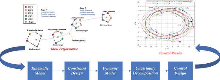 Figure 1
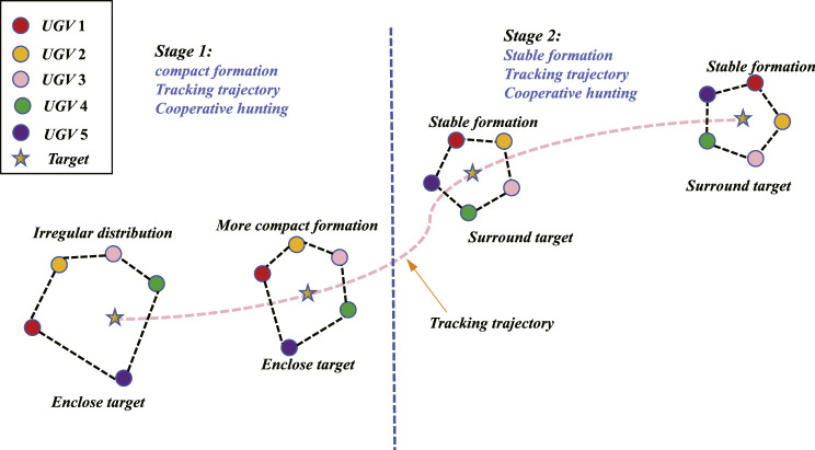 Figure 2
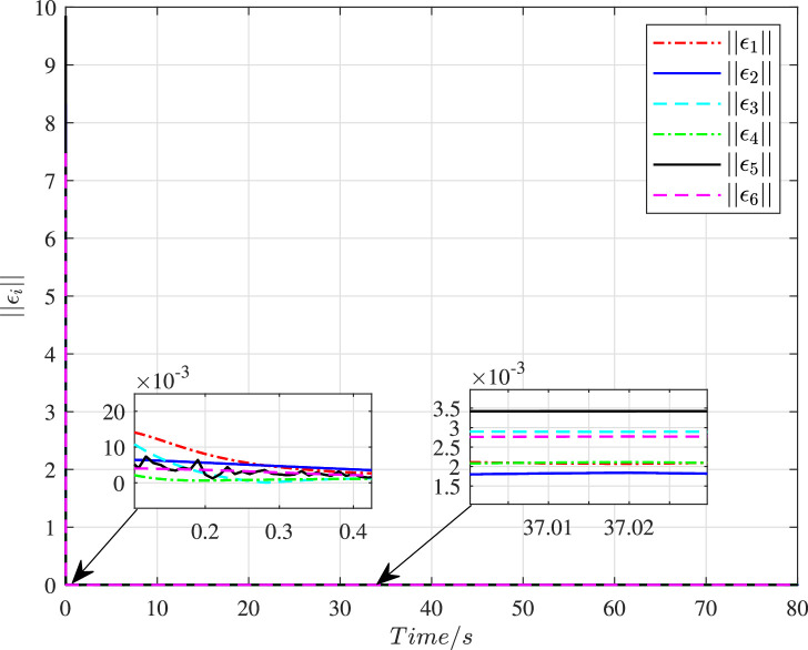 Figure 3
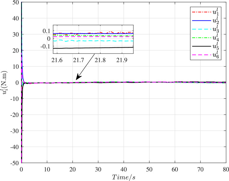 Figure 4
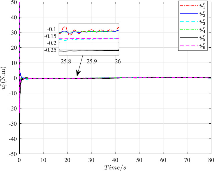 Figure 5
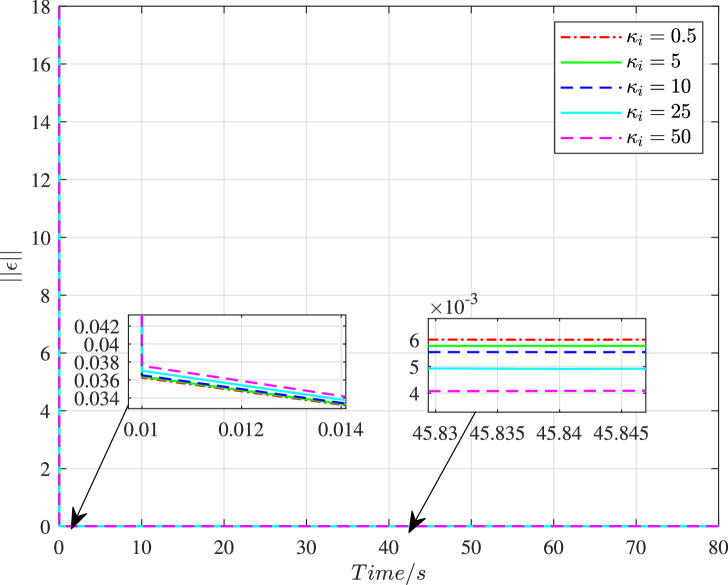 Figure 6
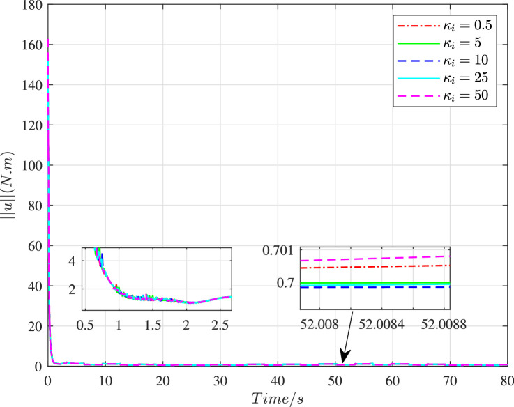 Figure 7
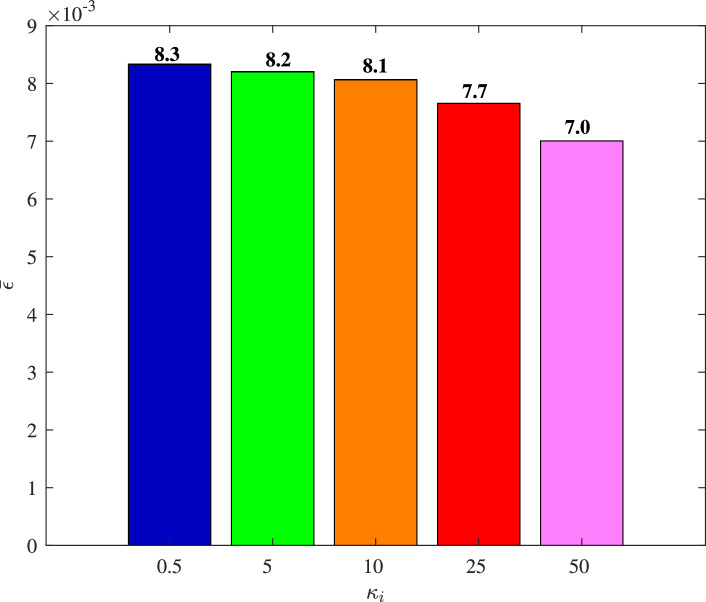 Figure 8
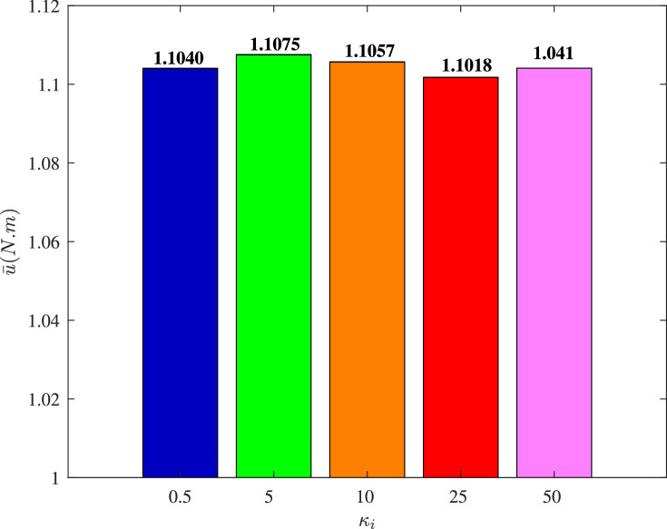 Figure 9
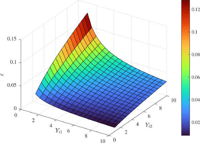 Figure 10
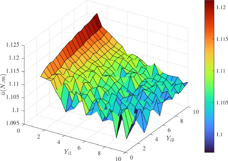 Figure 11
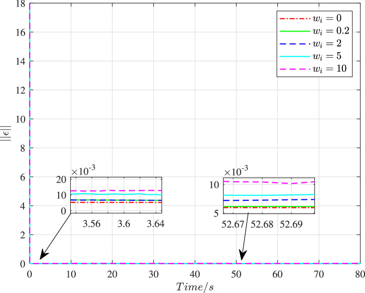 Figure 12
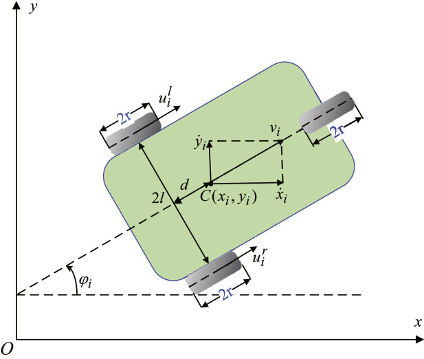 Figure 13
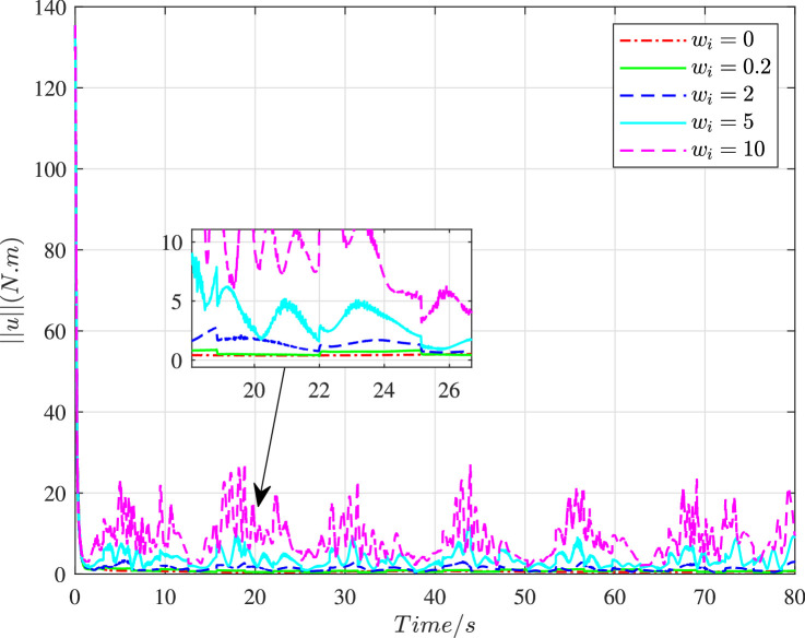 Figure 14
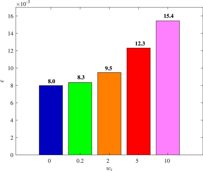 Figure 15
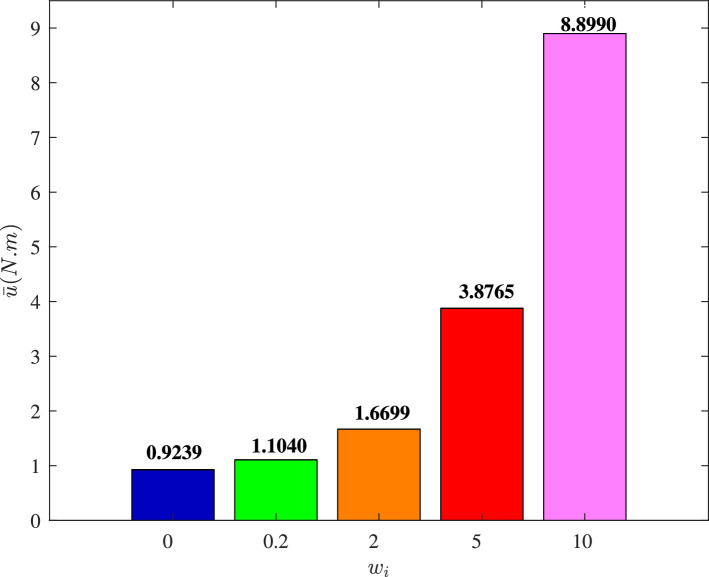 Figure 16
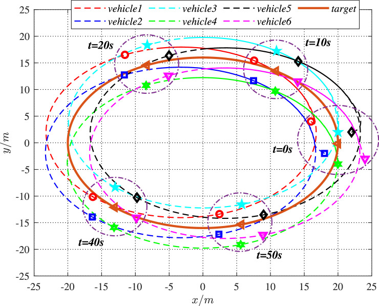 Figure 17
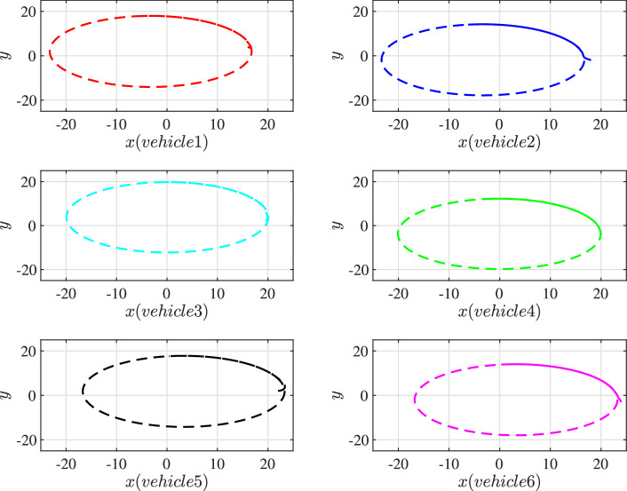 Figure 18
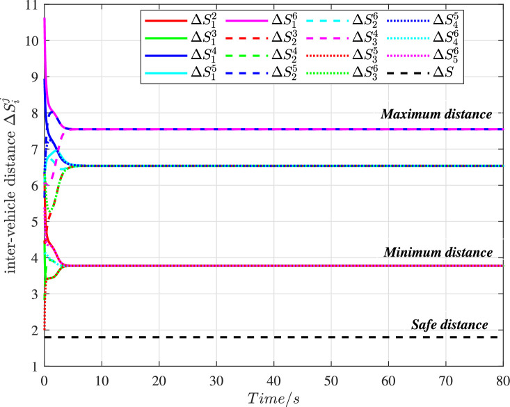 Figure 19
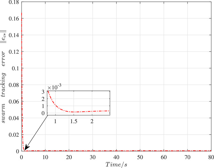 Figure 20
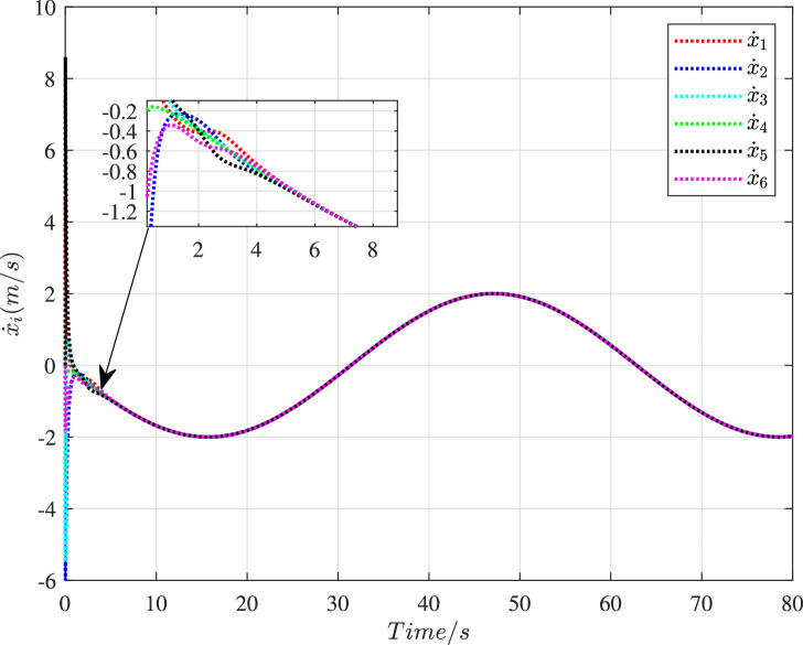 Figure 21
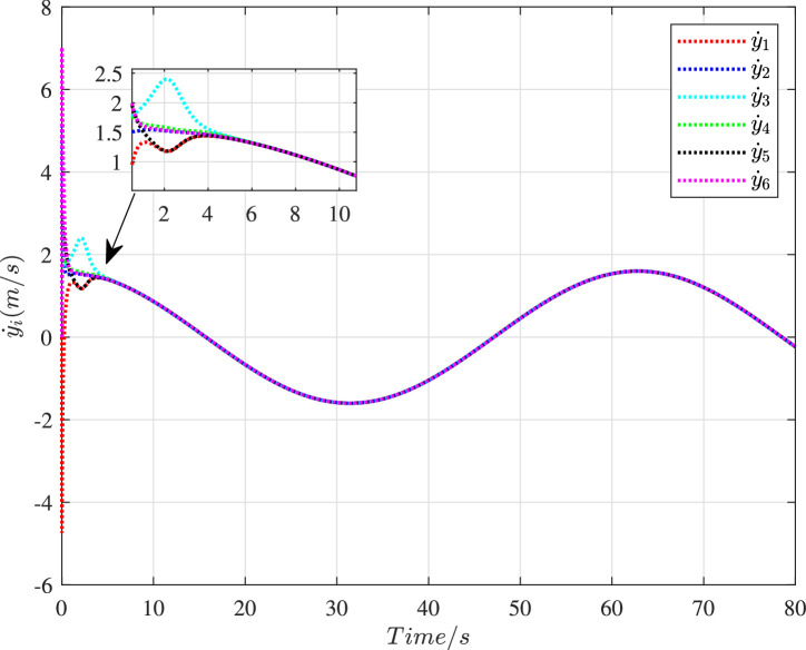 Figure 22
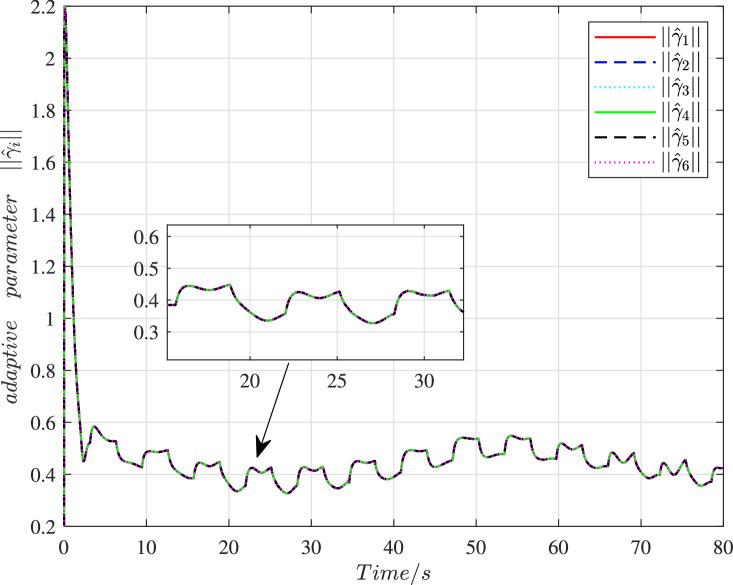 Figure 23
Peer Reviews
No public reviews on file for this paper yet. If you reviewed it on a platform where reviews are public (OpenReview, ICLR, NeurIPS, ICML), you can paste yours below so the community can read it here.
Videos
No videos yet. Explain this paper in a talk, walkthrough, or lecture? Add one.
Taxonomy
TopicsRobotic Path Planning Algorithms · Evacuation and Crowd Dynamics · Autonomous Vehicle Technology and Safety
Introduction
1
In the biological world, swarm behavior is a common sight, which can be seen everywhere. Examples can be found in certain social species, such as ant colonies, fish schools and sheep flocks. Based on simple interaction and collaboration between each other, these biological swarms can finalize some sophisticated tasks, which may be difficult or even impossible for any single individual to complete [1]. With the advanced technology and deepening research, engineers introduced the concept of swarm into mechanical systems and thereby derived the swarm mechanical systems. Nowadays, swarm mechanical systems are no longer unfamiliar. The research on swarm mechanical systems spans multiple fields and disciplines, such as unmanned aerial vehicle (UAV) swarm systems, unmanned ground vehicle swarm systems and unmanned underwater vehicle swarm systems [2], [3], [4]. Each agent in a swarm mechanical system is erected by mechanical devices. They follow the similar pattern as in biological swarms and possess a wide range of potential applications.
Mimicking the behaviors of social animals, a swarm of coordinated robotic agents can be used for shepherding [5], military security affairs [6], disaster relief and rescue work [7]. In the biomedical field, the magnetic microrobotic swarms with highly concentrated nanopreparations are expected to be applied for targeted drug delivery tasks [8], [9]. The increasing number of vehicles leads to the traffic jam problem. Hence, the Intelligent Transportation Systems (ITS) have been brought up. In the field of marine science, autonomous underwater vehicle (AUV) swarms are helpful for marine resource development and underwater target tracking, which can also be used as a network basis to build ITS for marine pollution monitoring [10]. As an important part and new trend of ITS, the Internet of Vehicles (IOVs) have attracted extensive attention of scientific and industrial circles. The essence of IOV is the application of Internet of Things (IOT) in ITS. IOVs make the application of swarm concept in ITS workable. The introduction of swarm architecture makes the ITS more compact, safe, economical and efficient [11]. A holistic framework for fully autonomous ground vehicles (FAGVs) in the smart city is proposed in [12], in which the swarm behavior coordination of FAGVs contributes to the construction of a safer, sustainable and efficient smart city.
Herd animals rely on chemicals or signs to communicate and coordinate their corresponding synergistic tasks, while the information interaction between agents in the artificial swarm system relies on various communication networks [13]. The individual agents should have capabilities of communication, sensing and local processing [14]. From this perspective, the artificial swarm systems can also be treated as cyber-physical systems (CPSs) in a sense [15]. When the system is interfered by network, catastrophic or even fatal consequences may be brought about if there are no proper defensive countermeasures. Therefore, the cyber interference issues are vitally important as a branch of network security in the swarm mechanical systems. In this context, consideration of the network and cyber space is a prerequisite for the proper control of artificial swarms. In order to compensate for interference lost and guarantee the system performance, effective resilient control strategies also received significant attention in the academic research. In [16], a distributed output-feedback controller is proposed to handle the cooperative output containment problem of the multigroup systems under cyber interference and infiltration. A decentralized hybrid controller targeting homogeneous vehicle platoons is designed in [17], which can show an effective resilience to DoS attacks and guarantee the system string stability. In addition, event-triggered mechanism [18], model predictive control methods [19], adaptive sliding-mode cooperative control [20] and robust control theories [21] have also been demonstrated valid to enhance the cyber security and robustness of the CPSs.
This paper explores the cooperative control problem for the unmanned ground vehicle (UGV) swarm system with system uncertainty and cyber interference. The main contributions of this paper can be summarised as follows. (i) The integrated kinematic model including compact formation, cooperative hunting and trajectory tracking of the UGV swarm system is presented, which is further regarded as the active constraints. (ii) Considering both system uncertainty and cyber interference inputs, the dynamic model of the UGV swarm system is constructed based on the proposed kinematic model. (iii) On the premise of decomposition of uncertainty and cyber interference input, a novel adaptive robust controller is proposed. The resilience to cyber interference is demonstrated by both theoretical derivation and simulations. The cooperative control drives the UGVs to achieve the kinematic performances approximately. We can state this paper as follows. Section 2 depicts the ideal kinematic model for the UGV swarm system. Section 3 presents the dynamic model for the swarm system under cyber interference. Section 4 articulates the design process of the cooperative control. Section 5 analyses the control performance of the system. Section 6 raises an illustrative example. Section 7 presents the final conclusions.
The integrated kinematic model
2
We consider an UGV swarm system composed of agents, wherein the position information of all agents in the swarm system is accessible. We use to denote the position vector of the unmanned ground vehicle , , . Taking the performances of compact formation, cooperative hunting and trajectory tracking into account, an integrated type of kinematic model for the th UGV is presented as
here , represents the potential function between UGV and UGV , represents the potential function between UGV and the reference trajectory (or the target). The first term on the right hand of (1) represents the performance of compact formation, while the second term represents the trajectory tracking performance. Both the first term and second term contributes to the performance of cooperative hunting.
Take for example, the desirable motion diagram of the UGV swarm is shown in Fig. 1. That means, in the desired state, the target is always surrounded by the UGVs, meanwhile, these UGVs can construct a stable formation and track the reference trajectory.Fig. 1The desirable motion diagram of the UGV swarm ( ).Fig. 1 dummy alt text
Let denote the attraction/repulsion function. We define as the swarm centroid. Let represent the reference trajectory of , then we define . Serving for the kinematic model, the following properties need to be satisfied [22], [23].Property 1The potential function can be converted to a new function : with respect to the relative position vector . That is,
Similarly, there exists a new function that guarantees
Property 2For each and , the following functions have symmetric characteristics:
Property 3For each and , there exists a hypersphere with center and radius , such that (i) if , then ; (ii) if , then .Property 4For the function , there exists a new function : , such that
Further, we can get
where and are positive scalar constants.Property 5The function can be expressed as
For simplicity, let , and the function will satisfy that
Remark 1Properties 1 and 2 reveal that the inter-individual action within the swarm only relies on the relative position, and these roles are mutual. Property 3 shows that the direction of the attraction/repulsion function is determined. The repulsive force is shown when the relative distance is too close, while the attractive force is shown when the relative distance is far enough. Since the equilibrium distance is , the collision avoidance can be converted as , where is the safety radius. Properties 4 and 5 show the linear factorization of the corresponding functions and . The inequality 2.7 in Property 4 can also lay the foundation for the realization of the following Performance 2. All of the properties indicate the formation characteristics of the swarm.
Based on the above properties, the following performances will be derived.Performance 1For any , we have
Performance 2Let , and the error vector . Under the properties 1–5, the error vector is uniformly bounded (For any , there exists a positive , then for all if is met) and uniformly ultimately bounded (For any and , there is a and a positive such that for any as Performance 3Let denote the swarm tracking error. Subject to Properties 1–4, . When , we can get
where represents the convex hull.Remark 2Performance 1 describes the features of the functions and . The action of UGV on and the action of UGV on are equal in magnitude and opposite in direction. Performance 2 shows that the swarm size is bounded, which also reflects the aggregation and formation characteristics of the swarm. Performance 3 depicts the cooperative hunting feature and swarm tracking capability, wherein all UGVs could enclose and surround the target.
Dynamic model with uncertainty and cyber interference
3
The dynamic model of UGV swarm system with uncertainty and cyber interference can be expressed as
wherein denotes the uncertain parameters, denotes the inertial matrix, denotes the Coriolis/centrifugal terms, denotes the gravitational terms; the is the input matrix of cyber interference, is the unknown cyber interference input, is the control input, is the uncertain factor due to cyber interference (such as Denial of Service, spoofing and/or the mixed threat interferences). Matrices/vectors , , and are of appropriate dimensions. Functions , , and are all continuous.
Inspired by the Udwadia-Kalaba constraint following modeling method, the integrated kinematic model (1) can be viewed as a series of constraints [24], [25], [26]. Suppose the constraints imposed on the independent th UGV can be rewritten as
where , , and are both .
They can also be reorganized with the matrix form
where , .
There are two perspectives to interpret these constraints. From one perspective, they are regarded as passively applied. That is, the corresponding constraint forces may be supplied by the external environment (or the system structure), which can enable the system to comply with the constraint condition. From another perspective, they are viewed as active. That is, the required forces are provided by the control input of the system to meet the constraints.
In contrast with the traditional integrating methods, here we perform differential operations on the constraints with respect to :
The second-order constraints can be expressed as
Rewriting Eq. 17 into the matrix form yields
where .Remark 3The system model (13) is unsettled, wherein the control input remains to be determined. Eqs. 14-18 can be regarded as the procedure of constraint processing. Notice that this treatment method makes the constraints change fundamentally. Hence, in order to drive the system to present the ideal kinematic characteristics, we should take this issue into account. That is, supplementary item shall be added in the control design to make up for this. The details will be stated in the next section.
Cooperative control design
4
Taking both uncertainty and cyber interference into account, we propose a class of cooperative controls in this section. The resulting control should guarantee the UGV swarm system to achieve the kinematic performances. Next, we will decompose the system uncertainty and cyber interference input matrix respectively to serve for the control design.
Uncertainty decomposition
4.1
Assumption 1The inertial matrix is positive definite for each , .
In most applications, this assumption is valid or even can be regarded as a common sense to some degree. Here we give it in the form of assumption for more accurate explanation. On this basis, let represents the nominal portions with , then the following decompositions and equations are valid.
Assumption 2The matrix is of full rank for each , so the matrix is invertible.
Based on Assumption 2, for the given positive definite matrix , we define
Assumption 3For all , there exists a scalar such that
Remark 4The bound of the uncertainty is unknown, so the value of constant is unknown. If there is no uncertainty in the system, then we have . Based on the continuity theory, this assumption imposes the influence of uncertainty within a certain threshold, and this threshold is unidirectional.
Cyber interference input matrix decomposition
4.2
With Assumption 2, we can derive the is invertible, then we have the following decompositions:
where
Lemma 1For any uncertain vector , it is within the zero space of the matrix . That is,
Proof
Q.E.D. □Remark 5Based on the above decompositions, the uncertain cyber interference input through the matrix will not influence the system performance, which can be utilized in the next control design.
Adaptive robust control design
4.3
For the UGV swarm system with uncertainty and cyber interference input, we propose a cooperative adaptive robust control method.Assumption 4There exists a positive lower bound (known or unknown) of the uncertain factor , such that for all .Assumption 5Let and then we make the following assumptions.(i) There exists an unknown constant vector and a known function : , such that
for all .(ii) The function is continuous, concave and nondecreasing with respect to each element of . For any and ,
Remark 6The function describes the structure of the uncertainty bound. The assumption parameterizes the worst-case effects associated with uncertainty.
Define constraint-following error . With the above assumptions, we define the following two portions
where denotes positive scalar design parameter; the and are all positive definite; denotes the estimated value of , with the initial condition that .
As a result, the cooperative adaptive robust control can be designed as
where the nominal feedback control term can direct the swarm system towards the desirable constraints and stabilize the nominal system, and the adaptive robust control term is to counteract the interference of uncertainty and cyber interference input, which can be tuned in real time by the value of the adaptive parameter .Theorem 1Let , . Subject to the previous assumptions, the cooperative control renders the system error *uniformly bounded (UB) and uniformly ultimately bounded (UUB).*ProofThe Lyapunov function candidate can be chosen as
where .For better differentiation, we define
Taking the derivative of yields
Since and , the reorganized terms can be written as
By Eq. 25, , then we have
Based on Eq. 26,
□
The rest terms relevant to can be converted to
Recalling and performing matrix operations,
Based on Eqs. 23 and 24, the rest terms can be rewritten as
Combining Eqs. 40 and 41, we have
The rest terms relating to can be rewritten as
Based on the matrix operations,
By a similar algebra as for , we can show that
Combining (44) and (45),
Summarizing the above results, the evaluation of can be expressed as
Taking the derivative of yields
Therefore,
Since
The overall evaluation can be expressed as
We let , , , then
Let , , . As a result,
We define
By Rayleigh’s principle, we have
Let , , we have
The uniform boundedness can be guaranteed with
where
The uniform ultimate boundedness can also be demonstrated with
and
Q.E.D.Remark 7The UB performance guarantees that the control error can converge within a small region The UUB performance ensures that the error can be sufficiently small. That is, after a finite time the error can converge within a region The uniform ultimate boundedness not only demonstrates that the cooperative control assures the system stability, but also indicates that the finally enters a region smaller than the initial value under the proposed control.
Performance analysis
5
Definition 1For all , and , if there exists a region satisfying , the controlled system is viewed robust to the interference factor and the cyber interference input .
Based on the characteristics of UB and UUB, we continue to explore the impacts on the robust performance of the swarm system.
No cyber interference input
5.1
When the swarm system is not influenced by the cyber interference, then the intact control input can be imposed on the system, i.e., , . In such scenarios, , , , which are corresponding to the new , , , so the value of the can be denoted as
For determined , and , the desirable value of can be obtained by a suitable choice of .
Considering the cyber interference
5.2
If the swarm system suffers from cyber interference, the value of can be acquired based on (57). In the case, , and should account for the interference influence, which implies a greater . As a result, the value of in (57) is greater than that of , which means the degradation of the constraint following performance compared with the case 5.1. Moreover, it is worth noting that in (57) will always exist for any and finite (which relies on the bounds of and interference input ). This implies the robustness of the controlled swarm system when suffering from cyber interference.
An illustrative example
6
Consider a swarm system consisting of 6 homogeneous unmanned ground vehicles. Let denote the general coordinates of the th UGV. The model of UGV in the two-dimensional plane is shown in Fig. 2. There are two driving wheels mounted on the rear axis, and a front omni-directional wheel. The relevant parameters illustrations are shown in Table 1. Based on the Lagrangian methods, the dynamic model of UGV can be formulated as
where
here , .Fig. 2Model of the th vehicle.Fig. 2 dummy alt textTable 1Descriptions of the system parameters.Table 1 dummy alt textNotation/UnitDescription Mass Inertia moment Orientation angle Diameter of the driving wheels Distance between two driving wheels Distance between mass centre and rear axle Driving torque of the left wheel ( ) Driving torque of the right wheel ( ) the position in the X-direction the position in the Y-direction the velocity in the X-direction the velocity in the Y-direction the acceleration in the X-direction the acceleration in the Y-direction
Subject to the properties and ideal kinematic performances, the constraints can be designed as
where
here , , and are all positive scalar parameters.
The above constraint equations can be rewritten in the standard form of Eq. 15, so we have
Let denote the overall constraint following error, where . Let denote the overall control cost, where . For the specific time , the average constraint following error can be denoted as , and the average control cost can be denoted as .
We define , , here and denote the possibly time-varying uncertainty. For simulations, we set , , , , , , , , , , , , , , . The cyber interference input can be expressed as
Subject to Assumption 5, we choose ,
where , , , are unknown and positive parameters, and . The adaptive law is given as
The desired trajectory (target) which the swarm centroid need to follow is given as a ellipse:
We choose the cooperative control parameters as , , , . The initial conditions for each vehicle can be set as shown in Table 2.Table 2Initial conditions for each vehicle.Table 2 dummy alt textNotation/Uniti=1i=2i=3i=4i=5i=6 161820202224 4 22 42 3 000000 000000 0.020.020.020.020.020.02
It is noted that vehicles in the swarm system do not start with the constraint manifold when . Based on the above settings, the simulation results are shown in Figs. 3–22.Fig. 3The trajectories of the UGV swarm.Fig. 3 dummy alt text
Fig. 3 depicts the trajectories of the 6 vehicles in the swarm system under the cooperative control (31). For better distinguish, the trajectories, starting positions and ending positions of UGVs are identified by different color lines and markers. At the initial moment, the UGVs are arbitrarily distributed. Driven by the designed control, the UGV swarm suffering form cyber interference can move along the desired trajectory (the “target” line) and gradually form a stable formation. It can be seen that the target are always surrounded by the 6 vehicles, which shows the cooperative hunting performance of the swarm. In Fig. 4, the trajectories of these vehicles are multiple ellipses around the tracking target, which further demonstrates the tracking performance of the swarm in a clearer way.Fig. 4Individual trajectories of 6 vehicles.Fig. 4 dummy alt text
We define as the inter-vehicle distance to observe the position relationship of unmanned ground vehicles at different times, and the histories of which can be shown in Fig. 5. For the safe radius , we have the safe distance . It can be seen that the distances are all significantly greater than the safe distance . That means, the collision avoidance of the swarm system can be guaranteed. Furthermore, these distances can quickly reach an equilibrium value and maintain this stable state, which further reflects that the swarm system under cyber interference can accomplish formation objectives under the proposed control. The maximum distance makes the formation more compact and further shows that the swarm size is bounded, which is consistent with Performance 2.Fig. 5The histories of inter-vehicle distance in the swarm system.Fig. 5 dummy alt text
Fig. 6 shows the time histories of the swarm tracking error under the cooperative control. Apparently, the tracking error could settle to zero within 1.5 s. In Figs. 7 and 8, the histories of velocity in the X-direction and the Y-direction are presented respectively. It is obvious that the velocity state of these vehicles could realize the consensus after 4 s despite the existence of cyber interference.Fig. 6The history of the swarm tracking error .Fig. 6 dummy alt textFig. 7The velocity histories of 6 vehicles in the X-direction.Fig. 7 dummy alt textFig. 8The velocity histories of 6 vehicles in the Y-direction.Fig. 8 dummy alt text
The time histories of the adaptive parameters can be shown in Fig. 9. These adaptive parameters would first increase to the maximum value, then gradually decay, and ultimately change in a stable region. Fig. 10 depicts the time variation of the constraint following error . It can be seen that these errors will quickly converge to zero even with a large initial deviation, so the constraint following performance under cyber interference can be sufficiently guaranteed. Figs. 11 and 12 demonstrate the control torques of driving wheels for all UGVs in the swarm system. They could gradually drop to a smaller region and their maximum value will not exceed the upper limit .Fig. 9Adaptive parameter history.Fig. 9 dummy alt textFig. 10History of the constraint following error .Fig. 10 dummy alt textFig. 11The histories of the control torque in the left wheel.Fig. 11 dummy alt textFig. 12The histories of the control torque in the right wheel.Fig. 12 dummy alt text
Figs. 13 and 14 show the time histories of overall constraint following error and the overall control cost with different . These errors show the similar trends, so they could all quickly converge to zero. The control cost can all drop to a smaller region with different . To explore the influence of , Figs. 15 and 16 compare the average constraint following error and the average control cost with different . The greater may reduce the average constraint following error but require different average control cost, which can serve as the reference for the choice of appropriate parameters. Figs. 17 and 18 compare the average constraint following error and the average control cost with different and . The greater and smaller may lead to a smaller average constraint following error. The average control cost with different values of and is within a small range, and the average control cost is small when the value of is large and that of is small.Fig. 13The overall constraint following error with different .Fig. 13 dummy alt textFig. 14The overall control cost with different .Fig. 14 dummy alt textFig. 15The average constraint following error with different .Fig. 15 dummy alt textFig. 16The average control cost with different .Fig. 16 dummy alt textFig. 17The average constraint following error with different and .Fig. 17 dummy alt textFig. 18The average control cost with different and .Fig. 18 dummy alt text
We set , and choose different values of to illustrate the impact of cyber interference input with different intensities on the system performance, the simulation results of which are shown in Figs. 19–22. It is noted that means no cyber interference input, so meanwhile. The time histories of the overall constraint following error and the overall control cost with various are shown in Figs. 19 and 20. It can be seen that the overall constraint following error can converge to a smaller range close to zero under the proposed control, whether there is cyber interference input with different intensities or no cyber interference input. Observing the overall constraint following error with different , the error with no cyber interference input is smaller than that with cyber interference input, which is consistent with the performance analysis in Section 5. What’s more, the larger may require higher overall control cost. In order to intuitively explore the impact of cyber interference input, Figs. 21 and 22 compare the average constraint following error and the average control cost under different . It is evident that the larger , which means stronger cyber interference input, can result in greater average constraint following error and require higher average control cost.Fig. 19The overall constraint following error with different .Fig. 19 dummy alt textFig. 20The overall control cost with different .Fig. 20 dummy alt textFig. 21The average constraint following error with different .Fig. 21 dummy alt textFig. 22The average control cost with different .Fig. 22 dummy alt text
Conclusion
7
The control issue of artificial swarm systems considering cyber interference is an inevitable topic. In face of challenges such as system dynamics, uncertainty and the effects of interference inputs, a skillful control approach is fundamental to the realization of the swarm performance. For the UGV swarm system, a cooperative control framework is elaborated, wherein various elements including constraints, kinematics, dynamics, uncertainty and cyber interference are taken into account. Inspired by the Udwadia-Kalaba approach, ideal kinematic model could be converted to the desirable constraints, then the nominal feedback control term and the adaptive robust control term can be designed accordingly. Under such a control framework, the global stability, uniform boundedness, uniform ultimate boundedness, compact formation, cooperative hunting and trajectory tracking can be guaranteed even there exist system uncertainty and cyber interference. The proposed cooperative control may have broad application potential such as military patrol, material allocation, target capture, etc.
Declaration of competing interest
The authors declare that they have no conflicts of interest in this work.
The reference list from the paper itself. Each links out to its DOI / PubMed record.
- 1Karaboga D.Gorkemli B.Ozturk C.A comprehensive survey: Artificial bee colony (abc) algorithm and applications Artif. Intell. Rev.42120142157
- 2Xia Z.Du J.Wang J.Multi-agent reinforcement learning aided intelligent uav swarm for target tracking IEEE Trans. Veh. Technol.7112022931945
- 3Eskandarian A.Wu C.Sun C.Research advances and challenges of autonomous and connected ground vehicles IEEE Trans. Intell. Transp. Syst.222202168371110.1109/TITS.2019.2958352 · doi ↗
- 4Fischell E.M.Kroo A.R.O’Neill B.W.Single-hydrophone low-cost underwater vehicle swarming IEEE Rob. Autom. Lett.522020354361
- 5Long N.K.Sammut K.Sgarioto D.A comprehensive review of shepherding as a bio-inspired swarm-robotics guidance approach IEEE Trans. Emerg. Top. Comput. Intell.442020523537
- 6Madhu A.Kumar H.M.B.Prajeesha Positioning optimization of drones using imu and securing uav communication by implementing hybrid cryptosystem 2021 5th International Conference on Trends in Electronics and Informatics (ICOEI)202168168610.1109/ICOEI 51242.2021.9452741 · doi ↗
- 7Trotta A.Montecchiari L.Felice M.D.A gps-free flocking model for aerial mesh deployments in disaster-recovery scenarios IEEE Access 820209155891573
- 8Ryan P.Diller E.Magnetic actuation for full dexterity microrobotic control using rotating permanent magnets IEEE Trans. Rob.336201713981409