Photochromic Molybdate for Advancing Anode Capacity of Lithium‐Ion Battery
Xiao‐Yue Zhang, Jian‐Ping Chen, Ping‐Wei Cai, Shou‐Tian Zheng, Cai Sun

TL;DR
A new photochromic molybdate material is introduced to improve lithium-ion battery anode performance without complex equipment.
Contribution
The first use of a photochromic polyoxomolybdate to enhance LIB anode capacity and rate performance is presented.
Findings
The material MV[Mo9O28] forms a stable charge-separated state after UV irradiation, lasting up to 2 years.
The anode capacity increases by 132 ± 14 mAh·g−1 after coloration and retains 7.6% more capacity at higher current densities.
Theoretical calculations confirm the stable charge-separated state is responsible for improved performance.
Abstract
Decoupling strategies can effectively enhance lithium‐ion battery (LIB) capacity, but suffer from the need for complex equipment, preventing widespread applicability. This work offers, for the first time, a decoupling strategy of electron‐transfer photochromism to improve LIB anode performance, without requiring complex equipment. The approach utilizes a new crystalline photochromic molybdate, MV[Mo9O28] (1, MV = methyl viologen cation) as the LIB anode. After UV irradiation, the initial 1 undergoes electron transfer from O to Mo, accompanied by a color change from colorless to blue and the generation of an ultra‐stable charge‐separated state with a lifetime of up to 2 years under ambient conditions. The observed capacity increases by 132 ± 14 mAh· g−1 across various current densities after coloration, along with superior rate performance—retaining 7.6% more capacity than the initial…
Genes, proteins, chemicals, diseases, species, mutations and cell lines named across the full text — each resolved to its canonical identifier and authoritative record.
Click any figure to enlarge with its caption.
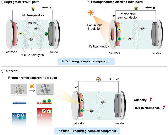 Figure 1
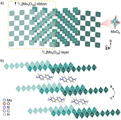 Figure 2
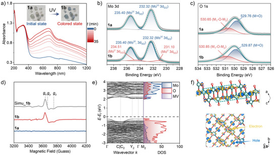 Figure 3
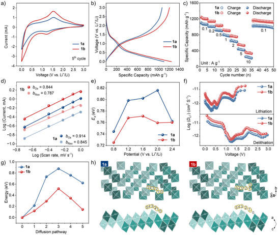 Figure 4
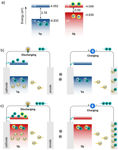 Figure 5
- —National Natural Science Foundation of China10.13039/501100001809
- —Natural Science Foundation of Fujian Province10.13039/501100003392
Peer Reviews
No public reviews on file for this paper yet. If you reviewed it on a platform where reviews are public (OpenReview, ICLR, NeurIPS, ICML), you can paste yours below so the community can read it here.
Videos
No videos yet. Explain this paper in a talk, walkthrough, or lecture? Add one.
Taxonomy
TopicsTransition Metal Oxide Nanomaterials · Advancements in Battery Materials · Photochromic and Fluorescence Chemistry
Introduction
1
The burgeoning global demand for advanced technologies, such as large‐scale energy storage systems, electric vehicles, and consumer electronics, has driven the need for rechargeable batteries that combine high safety, eco‐friendliness, cost‐effectiveness, and superior energy density. Lithium‐ion batteries (LIBs), known for their high energy density and long lifespan, have become widely utilized in portable electronic devices and electric vehicles.^[^ 1, 2, 3 ^]^ However, the limited theoretical capacity of commercial graphite anode (≈372 mAh g^−1^), and the sluggish kinetics of Li^+^ intercalation/deintercalation restrict their potential to meet the growing energy and power demands of next‐generation energy storage systems.^[^ 4, 5 ^]^ Exploring novel anode materials with high specific capacity and fast rate performance, to fulfil the primary requirements of LIBs, remains a long‐standing and challenging pursuit.
Numerous strategies have been reported to enhance the capacity of batteries, including electrolyte optimization,^[^ 6 ^]^ and electrode material modification.^[^ 7, 8 ^]^ In recent years, the decoupling strategy with additional H^+^/OH^−^ pairs or electron–hole pairs, offers an efficient approach to enhance battery performance (Figure 1). For example, electrolyte decoupling enables the anode to work in an alkaline electrolyte and the cathode operates in an acidic electrolyte, separately, the H^+^/OH^−^ pairs participate in the cathode/anode reactions, respectively, contributing additional capacity to the system (Figure 1a).^[^ 9, 10, 11, 12 ^]^ Moreover, photoactive semiconductor electrodes can generate photogenerated electron–hole pairs under light illumination, and the efficient separation and transport of these photogenerated charge carriers can significantly enhance the battery capacity (Figure 1b).^[^ 13, 14, 15 ^]^ However, the former approach requires a physical separator, which increases the complexity and cost of the battery, while the latter depends on continuous light illumination to achieve capacity enhancement. The development of a decoupling method without complex equipment for enhancing the capacity of LIBs remains a challenge.
Decoupling strategy. a) Segregated H+/OH− pairs generated by multi‐separators. b) Photogenerated electron–hole pairs requiring continuous irradiation. c) Photochromic electron–hole pairs without requiring complex equipment.
Electron‐transfer photochromic materials have been reported to form charge‐separated states after coloration,^[^ 16, 17 ^]^ in which electrons and holes remain stable for prolonged durations. It has been recently demonstrated that N‐heterocyclic aromatic cations, particularly methylviologen (MV), can further effectively stabilize these states through π‐cation polarization effects.^[^ 18 ^]^ Meanwhile, molybdenum oxides (MoO_x_) have been extensively investigated as anode materials for LIBs owing to their high theoretical capacity and environmental friendliness.^[^ 19, 20, 21, 22 ^]^ Inspired by these, we synthesized a novel inorganic–organic hybrid molybdate, MV[Mo_9_O_28_] (1), by incorporating MV as the counteraction. Compound 1 exhibits photochromic behavior via photoinduced electron transfer (PIET) from O to Mo upon UV irradiation (Figure 1c). Remarkably, the charge‐separated state persists for up to 2 years under ambient conditions. Interestingly, the specific capacity increases by 132 ± 14 mAh·g^−1^ after coloration across various current densities, accompanied by significantly enhanced rate capability, demonstrating 7.6% higher capacity retention compared to the initial state, even at a 100‐fold increase in current density. Distinct from previously reported photo‐assisted batteries, our proposal strategy requires only a short UV‐light stimulus to achieve sustained enhancement in capacity. Comprehensive experiment and density functional theory (DFT) calculations reveal that the additional electrons and holes contribute to increasing the electrical energy stored in LIBs, leading to the enhanced specific capacity, and the charge‐separated state effectively accelerates Li^+^ ions transfer, enabling excellent rate capacity. To our knowledge, this is the first successful application of photochromic charge‐separated to enhance capacity in LIBs.
Results and Discussion
2
Compound 1 was synthesized by a hydrothermal reaction of Na_2_MoO_4_·2H_2_O and MVCl_2_ at 160 °C for 72 h with pH adjusted to 1 using HCl (4 m). The crystallographic phase purity of 1 was systematically characterized by powder X‐ray diffraction (PXRD, Figure S1, Supporting Information), IR spectrum (Figure S2, Supporting Information), and elemental analyses (experimental details provided in the Supporting Information). Thermogravimetric analysis (Figure S3, Supporting Information) reveals that 1 exhibits excellent thermal stability below 350 °C.
As shown in Figures 2 and S4 (Supporting Information), the crystal structure of 1 consists of 2D ^2^/∞[Mo_9_O_28_]^2−^ anionic layers separated by MV^2+^ cations. The layer belongs to the reported ^2^/∞[Mo_n_O_3n+1_]^2−^ family,^[^ 23 ^]^ with n = 9. The nine distorted [MoO_6_] octahedra connect each other by corner‐sharing in an interleaved manner to yield [Mo_9_O_46_] (Mo_9_) block unit. Then the Mo_9_ units further link themselves by corner‐sharing, resulting in an infinite ^1^/∞[Mo_9_O_38_] ribbon extending along the b direction. Each ribbon is sandwiched via edge‐sharing condensation between two adjacent ribbons shifted along in two opposite [101] directions with half‐overlapping, to form a stair‐like 2D ^2^/∞[Mo_9_O_28_]^2−^ layer, with the step width being exactly half of those of the ^1^/∞[Mo_9_O_38_] ribbon (Figure 2a). The interlayer spacing is 6.58 Å, with MV^2+^ inserted as counter‐cations between the layers, which may facilitate Li^+^ intercalation and diffusion, and establishes the structural basis for high Li^+^ storage capacity. The perpendicular distance from the N atom in MV^2+^ to the molecular plane of its adjacent MV^2+^ is 3.52 Å (Figure S5a, Supporting Information). A significant lateral offset exists between two adjacent MV^2+^ molecules, resulting in a distance of 4.76 Å from the N atom to the center of the pyridine of adjacent MV^2^ ^+^, indicating negligible π–π interactions. In addition, a wide hydrogen bonding network exists between the molybdate layer and MV^2+^ (Figure 2b; Figure S5b, Supporting Information), and the combination of strong electrostatic interactions and a diverse array of hydrogen bonding motifs contributes to the remarkable thermal stability of 1.
Structural of 1. a) The stair‐like 2D 2/∞[Mo9O28]2− layer. b) The pillared layered molybdate.
Under ambient conditions, colorless crystal (1a) turns blue (1b) when irradiated with a 500 W Hg lamp (≈110 mW \to cm^−2^, default light source hereafter). Time‐dependent electron absorption spectra (Figure 3a) show a new broad absorption band spanning 400–1200 nm for 1b, with an absorption maximum centered at 681 nm. The coloration reaches saturation after 35 min of irradiation. To reveal the photochromic mechanism, comparative analysis of PXRD (Figure S1, Supporting Information) and IR (Figure S2, Supporting Information) data for 1a and 1b demonstrates no significant structural changes during the coloration process, confirming the absence of structural isomerization or phase transitions after irradiation. Next, as shown in Figure 3d, no electron paramagnetic resonance (EPR) signal is detected for 1a, while characteristic unpaired electron signals are observed after coloration. The simulation of orthorhombic symmetry signals of g‐values at 1.938, 1.921, and 1.874, which are linked to superhyperfine coupling with the magnetic isotope Mo, conclusively demonstrates the presence of Mo^V^ and the occurrence of PIET. The orthorhombic symmetry features align with the structural characteristics of the distorted MoO_6_ octahedron. Therefore, the new absorption band can be attributed to an intervalence charge transfer (IVCT) process from Mo^V^ to Mo^VI^. The X‐ray photoelectron spectroscopy (XPS) data (Figure 3b,c; Figure S6, Supporting Information) provide further evidence for electron transfer behavior. Upon UV irradiation, significant changes are observed in the core‐level spectra of Mo 3d. Before coloration, there are two Mo 3d_3/2_ and 3d_5/2_ peaks of Mo^VI^ at ≈235.40 and 232.32 eV, respectively. After coloration, two new peaks emerge in the lower binding energy region of 234.51 and 231.10 eV, which can be attributed to the formation of partial Mo^V^. Further analysis of the O 1s spectral features reveals that the original peaks at 529.76 and 530.65 eV shift toward higher binding energies of 529.87 and 530.85 eV after coloration, indicating the O atoms as electron donors.
Photochromism of 1. a) Time‐dependent UV–vis spectra, inset, Color change after UV irradiation. b‐c) XPS (Al‐Kα) core‐level spectra of Mo 3d and O 1s; d) EPR spectra of 1a, 1b, and simulated 1b, where [g x, g y, g z] = [1.938, 1.921, 1.874], [A x, A y, A z] = [280, 380, 545] MHz. e) BS (left) and DOS (right). The Fermi level is set to zero. f) Electron density difference of molybdate layer, the dashed line indicates the primary charge‐separated region, yellow and blue colours represent charge accumulation and depletion after electron transfer, respectively, with an isosurface value of 0.004 e·Å−3.
The band structure (BS) and densities of states (DOS) data reveal a bandgap of ≈2.5 eV (Figure 3e; Figures S7 and S8, Supporting Information). The valence band (VB) maximum is mainly dominated by O atoms, while the conduction band (CB) minimum is primarily contributed by Mo atoms, indicating the ability for O to Mo electronic transfer. Furthermore, the electron density difference (Δρ) isosurfaces (Figure 3f) demonstrate that electrons are transferred from O atoms to Mo atoms, leaving holes localized on O atoms, forming a charge‐separated state, and the electron transfer primarily occurs at the platform of the molybdate layer rather than at the step. This charge separation creates a favorable internal electric field on the platforms, which may accelerate Li^+^ transport. Surprisingly, the charge‐separated state remains stable even after two years under ambient conditions (Figure S9, Supporting Information). The observation is consistent with the strong π‐cation polarization effect of MV^2+^, which effectively stabilizes the charge‐separated state.^[^ 18 ^]^
To investigate the impact of the charge‐separated state of 1 on LIB anode performance, we assembled 2032‐coin cells using 1 as anode materials and evaluated their performance. The cyclic voltammetry (CV) curves of 1a and 1b anodes (Figure 4a; Figure S10, Supporting Information) show a reduction peak at 1.21 V, which can be attributed to the reduction of Mo^VI^ to Mo^IV^.^[^ 21, 24 ^]^ The nearly overlapped CV curves after the fifth cycle without significant changes demonstrate the reversibility of Li^+^ insertion/extraction into/from the anode. Moreover, the CV curves of 1b exhibit a larger peak current density and integrated area compared with 1a, indicating its higher capacity. The galvanostatic charge and discharge (GCD) curves (Figure S11, Supporting Information) at the first cycle deviate from subsequent ones due to the formation of the solid electrolyte interface (SEI) film. Comparing the second GCD profiles (Figure 4b) at a current density of 0.1 A g^−1^, the discharge specific capacities are 1098 mAh g^−1^ (61.44 Li^+^ ions) and 1245 mAh g^−1^ (69.65 Li^+^ ions) of 1a and 1b, respectively, which are consistent with the results calculated from the CV curves at 0.2 mV s^−1^ (Figure S12, Supporting Information), indicating that 1b are conductive to promote the storage of a large amount of Li^+^ ions.
LIBs performance of 1. a) The CV curves in the initial fifth cycle at 1.0 mV s−1; b) GCD curves at 1.0 mV s−1; c) Rate performance; d) Current response plotted against scan rates; e) Activation‐energy profiles at various potentials; f) Relative Li+ ions diffusivity at 0.05 A g−1; g,h) Simulated Li+ ions diffusion energy barrier, and diffusion pathways on the molybdate layer for 1a and 1b, respectively.
The rate capacities were further evaluated. As shown in Figure 4c, both electrodes 1a and 1b exhibit reversible discharge specific capacities; however, 1b delivers consistently higher capacities by ≈132 ± 14 mAh g^−1^ than those of 1a across various current densities. When the current density was increased by a factor of 100 (to 10 A g^−1^), the capacity retention rates for 1a and 1b were 21.5% and 29.1%, respectively, further confirming the superior rate performance of 1b. When the current density returns to 0.1 A g^−1^, the capacity can be restored with a retention rate of 97.0%. The result can also be verified by the lower polarization voltage observed for the 1b electrode (Figure S13, Supporting Information). Moreover, the specific capacity and rate performance of 1b surpass those of excellent MoO_x_‐based anode materials (Table S4 and Figure S14, Supporting Information), further highlighting the significant advantages of the charge‐separated state in enhancing LIB capacity.
To investigate the origin of the capacity gain in the charge‐separated state, we further elucidate the charge storage mechanism of the LIB cells by collecting CV curves at different scan rates for electrodes 1a and 1b (Figures S15–S17, Supporting Information).^[^ 19 ^]^ As shown in Figure S18 (Supporting Information), the capacitive contribution percentage increases with scan rate for both electrodes. Notably, the capacitive contribution consistently dominates over the diffusion contribution across all scan rates, indicating capacitive‐dominated charge storage processes. Interestingly, after coloration, the proportion of diffusion contribution increases, suggesting that the charge‐separated state facilitates enhanced diffusion‐controlled faradaic contribution. The b‐values of the redox processes, which reflect the nature of the charge storage mechanism, are further analyzed. As displayed in Figure 4d, the b‐values for the redox processes are 0.914/0.845 and 0.884/0.787 for 1a and 1b, respectively, suggesting a charge storage mechanism leaning toward capacitive contributions. Specifically, the formation of the charge‐separated state induces an enhancement in the diffusive contribution, consistent with the discussion above.
The electrochemical impedance spectroscopy measurements are conducted to obtain the activation energy (*E_a_ *) of the electrode reaction (Figures S19–S21, Supporting Information). The maximum E a decreases from 0.82 eV in 1a to 0.76 eV in 1b (Figure 4e), indicating that electrode 1b is more favorable than the 1a thermodynamically, thereby facilitating lithiation/delithiation efficiency. Furthermore, galvanostatic intermittent titration technique tests (Figure S22, Supporting Information) are conducted to calculate the Li^+^ ion diffusion coefficients, demonstrating values of 3.83 × 10^−11^ to 5.36 × 10^−13^ cm^2^ S^−1^ for 1b during lithiation/delithiation (Figure 4f). In contrast, 1a exhibits significantly lower values of 8.79 × 10^−12^ to 3.14 × 10^−13^ cm^2^ S^−1^, highlighting the superior reaction kinetics of the 1b electrode. The DFT simulations are further performed to calculate the diffusion barriers for Li^+^ ions on the surface of the molybdate layer. As shown in Figure 4g,h, the diffusion energy barrier for the charge‐separated state is substantially lower than that in the initial state. A lower diffusion barrier facilitates faster ion migration. Therefore, the charge‐separated state effectively enhances the interlayer Li^+^ migration rate, thereby further improving the overall charging and discharging kinetics, as well as the enhancement of the diffusive contribution for total capacity.
In order to gain insight into the charge storage mechanism, in situ XRD (Figure S23, Supporting Information) and ex situ XPS (Figure S24, Supporting Information) techniques are used to analyze the structure and valence state changes of 1b during the charge/discharge process. The unchanged XRD patterns of 1b indicate no new phase generation in the charge/discharge process. The core‐level Mo 3d spectra of electrode 1b at open circuit voltage coincide with those in Figure 3b, exhibiting coexisting Mo^VI^ and Mo^V^ signatures. Upon discharging to 0.01 V, a new peak corresponding to Mo^IV^ emerges, confirming partial reduction of Mo atoms to obtain two‐electron during discharge. When recharged to 3.0 V, exclusively Mo^VI^ peaks are observed, demonstrating complete electron transfer from reduced Mo sites to the counter electrode via the external circuit.
Based above results, a phenomenological explanation for the capacity gain after coloration is proposed, as schematically illustrated in Figure 5 and Video S1 (Supporting Information). The bandgaps and energy level alignments (relative to the vacuum level) of 1a and 1b (Figure 5a) are determined by UV–vis–NIR absorption spectra (Figure S25a,b, Supporting Information) and CV curves (Figure S25c,d, Supporting Information). For the 1a electrode (Figure 5b), Li^+^ ions deintercalate from the anode and intercalate into 1a during discharge, while electrons enter its CB via the external circuit. During charge, this process reverses—Li^+^ ions deintercalate from 1a back to the anode, accompanied by oxidation of 1a and electron extraction from its CB. When 1b serves as the electrode (Figure 5c), it resides in a stable charge‐separated state with electrons in CB and holes in VB. During discharge, while electrons enter the CB of 1b via the external circuit, partial recombination of additional electrons with holes occurs in the VB, thus enabling enhanced Li^+^ intercalation into the 1b electrode. During charge, 1b releases more electrons from its CB comparing with 1a, alongside greater Li^+^ deintercalation, thereby increasing charge capacity. The complete depletion of electrons from the CB of 1b during charging corresponds to the disappearance of reduced Mo peaks observed in Figure S24 (Supporting Information). Crucially, the extra capacity gained during charging is reversibly released upon discharge. Since the additional holes in 1b are consumed by recombination during the first cycle discharge, all subsequent discharge processes involve electrons entering the CB exclusively. This mechanism consistently sustains the high specific capacity of 1b over extended cycling.
a) Schematic diagrams of band structure; b) Charging/discharging schematic diagrams showing advancing anode capacity of LIBs. Note, the electrons and holes of the charge‐separated state are outlined in yellow; the dashed arrow indicates partial recombination of additional electrons with holes in the VB during the first discharge cycle.
Conclusion
3
In summary, we report a novel decoupling strategy using electron‐transfer photochromism to enhance LIB anode performance without requiring complex equipment. After coloration, both capacity and rate performance are significantly improved, surpassing those of excellent MoO_x_‐based anode materials. The stable charge‐separated state not only provides additional electrons and holes, synergistically contributing to higher capacity, but also effectively accelerates Li^+^ ions transfer, enabling excellent rate capacity. This work presents the first example of enhanced LIB anode performance induced by the electron‐transfer photochromism, offering new insights into the strategy for developing high‐performance anode materials for LIBs.
Conflict of Interest
The authors declare no conflict of interest.
Supporting information
Supporting Information
Supplemental Video 1
Supporting Information
The reference list from the paper itself. Each links out to its DOI / PubMed record.
- 1Y. Liu , Y. Zhu , Y. Cui , Nat. Energy 2019, 4, 540.
- 2K. Kang , Y. S. Meng , J. Bréger , C. P. Grey , G. Ceder , Science 2006, 311, 977.16484487 10.1126/science.1122152 · doi ↗ · pubmed ↗
- 3B. Dunn , H. Kamath , J.‐M. Tarascon , Science 2011, 334, 928.22096188 10.1126/science.1212741 · doi ↗ · pubmed ↗
- 4X. Liu , Y. Liu , Z. Shao , G. Pan , Y. Peng , X. Wang , W. Gao , X. Yang , J. Wang , X. Zhang , K. Yang , Y. Chen , Y. Wu , J. He , Adv. Mater. 2025, 37, 2505136.10.1002/adma.20250513640509654 · doi ↗ · pubmed ↗
- 5L.‐L. Lu , Y.‐Y. Lu , Z.‐X. Zhu , J.‐X. Shao , H.‐B. Yao , S. Wang , T.‐W. Zhang , Y. Ni , X.‐X. Wang , S.‐H. Yu , Sci. Adv. 2022, 8, abm 6624.10.1126/sciadv.abm 6624 PMC 905402035486719 · doi ↗ · pubmed ↗
- 6I. Jeong , S. Kim , Y. Kim , C. Kim , J. Kang , J. H. Ha , Y. Cho , S. J. Kang , J. Ryu , J. W. Han , S. Park , Adv. Mater. 2024, 37, 2412652.10.1002/adma.20241265239726357 · doi ↗ · pubmed ↗
- 7L. Zu , Q. Su , F. Zhu , B. Chen , H. Lu , C. Peng , T. He , G. Du , P. He , K. Chen , S. Yang , J. Yang , H. Peng , Adv. Mater. 2017, 29, 1701494.10.1002/adma.20170149428635185 · doi ↗ · pubmed ↗
- 8J. Lu , X. Sui , K. S. Novoselov , P. Huang , F. Xu , L. Sun , Coord. Chem. Rev. 2024, 515, 215954.