Predictive Constitutive Modelling of Oxidation-Induced Degradation in 2.5D Woven C/SiC Composites
Tao Wu, Yukang Wang, Wenxuan Qi, Xingling Luo, Peng Luo, Xiguang Gao, Yingdong Song

TL;DR
This paper develops a model to predict how oxidation affects the strength and durability of ceramic composites used in high-temperature environments.
Contribution
A novel meso-scale constitutive model incorporating oxidation damage and fiber defect distribution in 2.5D woven C/SiC composites is proposed.
Findings
The model effectively characterizes strength degradation and stiffness reduction caused by oxidation.
High-temperature tests validated the model's accuracy at 700 °C, 900 °C, and 1100 °C.
The model provides a physics-based foundation for reliable design and life assessment of C/SiC components.
Abstract
Oxidation can lead to intrinsic degradation and loss in the load-bearing capacity of ceramic matrix composites (CMCs) in high-temperature service, thereby compromising structural integrity and operational safety. To elucidate the mechanism of its oxidation effects, this study predicted the oxygen diffusion coefficient within 2.5D woven C/SiC fibre bundles based on gas diffusion and oxidation kinetics theory, and subsequently constructed a meso-scale constitutive model incorporating oxidation damage and fibre defect distribution. Furthermore, a micro-scale framework for yarns was established by integrating interfacial slip behaviour, and an RVE model for 2.5D woven C/SiC was constructed based on X-ray computed tomography reconstruction of the actual microstructure. Building upon this foundation, an oxidation constitutive model applicable to loading–unloading cycles was proposed and…
Genes, proteins, chemicals, diseases, species, mutations and cell lines named across the full text — each resolved to its canonical identifier and authoritative record.
Click any figure to enlarge with its caption.
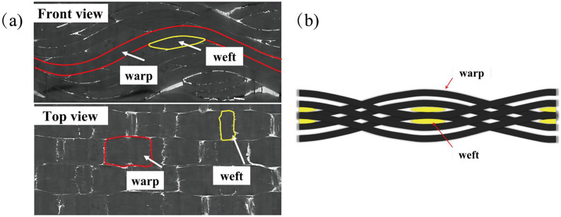 Figure 1
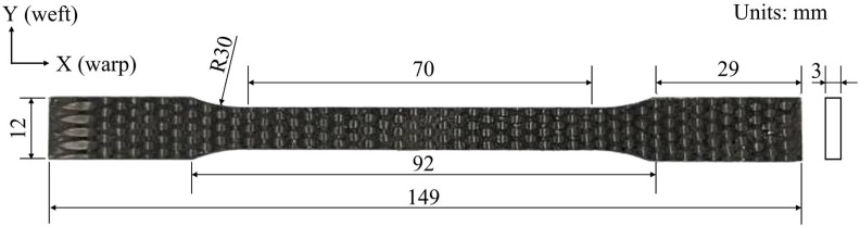 Figure 2
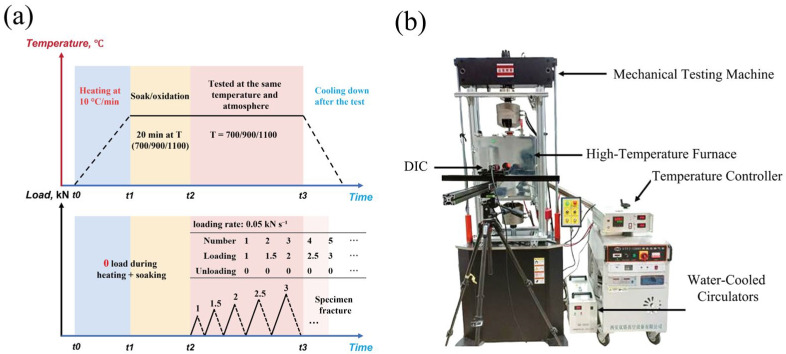 Figure 3
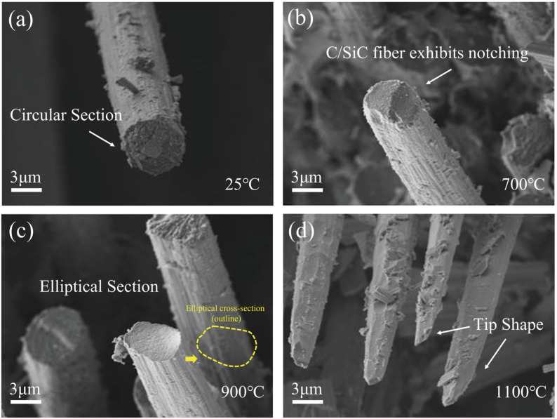 Figure 4
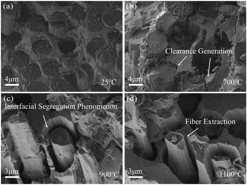 Figure 5
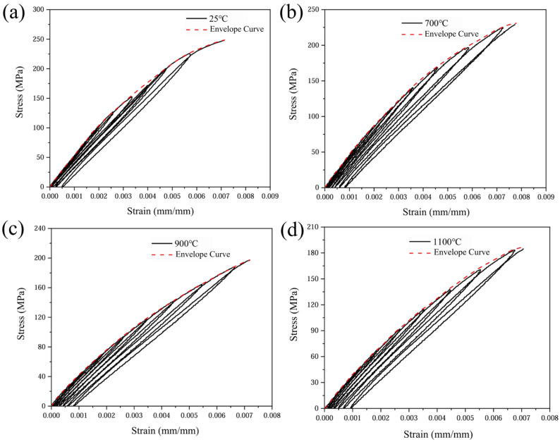 Figure 6
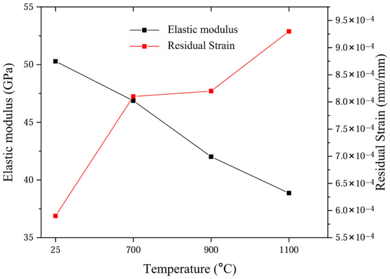 Figure 7
 Figure 8
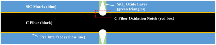 Figure 9
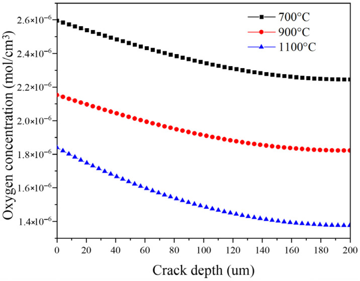 Figure 10
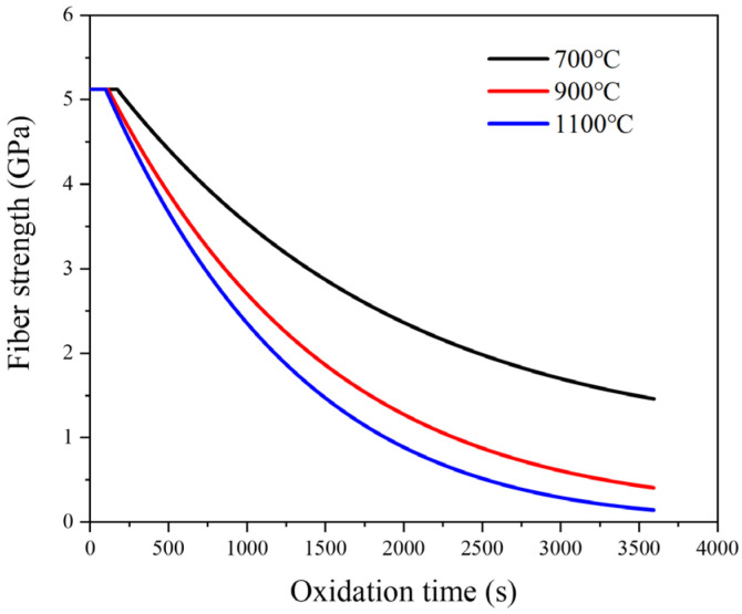 Figure 11
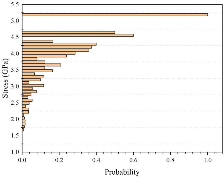 Figure 12
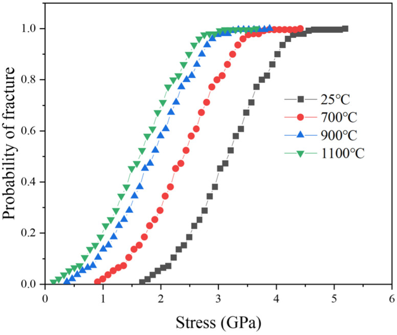 Figure 13
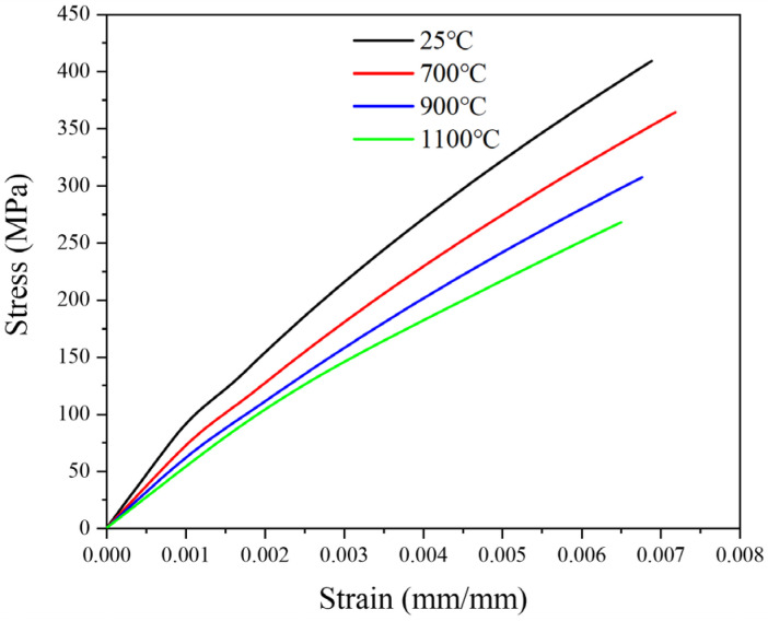 Figure 14
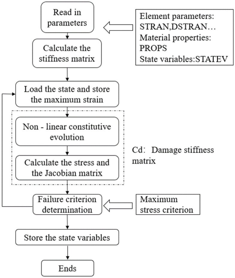 Figure 15
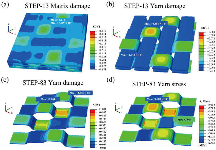 Figure 16
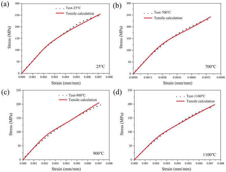 Figure 17
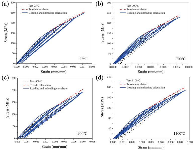 Figure 18
- —National Natural Science Foundation of China
- —Basic Research Program of Jiangsu Province
Peer Reviews
No public reviews on file for this paper yet. If you reviewed it on a platform where reviews are public (OpenReview, ICLR, NeurIPS, ICML), you can paste yours below so the community can read it here.
Videos
No videos yet. Explain this paper in a talk, walkthrough, or lecture? Add one.
Taxonomy
TopicsAdvanced ceramic materials synthesis · Fiber-reinforced polymer composites · Silicon Carbide Semiconductor Technologies
1. Introduction
Ceramic matrix composites (CMCs) are widely used in aero-engine hot-end components and hypersonic vehicle thermal protection systems due to their high-temperature stability, corrosion resistance and lightweight and high-specific-strength characteristics [1,2,3]. Among them, C/SiC composites have stability advantages in complex thermal environments, but are prone to significant oxidation processes under oxygen-rich high-temperature service conditions. The pores, microcracks and fibre–matrix interfaces within the material provide channels for oxygen diffusion, making the gradual evolution of oxidation damage a key factor limiting its lifetime and structural reliability [4,5,6].
Existing studies show that the oxidation behaviour of C/SiC exhibits typical staged characteristics and is controlled by the diffusion mechanism together with the interfacial structure [7,8,9]. In the lower temperature range (500–800 °C), oxygen mainly diffuses along the initial defects, and the material is dominated by the accumulation of mass loss. As the temperature rises (800–1100 °C), the permeability of the fibre bundles is enhanced and the thermally expanding microcracks are gradually connected; the gas transport mechanism is dominated by molecular diffusion and Knudsen diffusion, and interfacial depletion occurs in tandem with the weakening of the fibres [10]. At higher temperatures (above 1100 °C), the SiC matrix generates oxide films [11], the oxidation behaviour changes from reaction-controlled to film growth-controlled, its densification determines the ability of further oxygen diffusion, and the material is prone to enter into rapid embrittlement when the integrity of the film structure cannot be maintained [12,13,14]. The above multi-stage, multi-mechanism synergistic effect makes C/SiC in an oxidation environment present significant non-uniformity and multi-scale evolution characteristics.
Regarding the degradation of properties under oxidation conditions, studies have been conducted to analyze the damage modes, interfacial behaviours and fracture characteristics of C/SiC composites through macroscopic mechanical tests and microscopic characterization [15,16,17]. Vagaggini et al. [18] proposed a theoretical framework based on hysteresis response analysis, which was used to identify the mechanical characterization of different damage modes, such as debonding of fibre/matrix interfaces, cracking of the matrix, and damage of the fibres, under cyclic loading. Zhang et al. [19] studied the oxidation service behaviour of C/SiC by loading and fracture characterization in high-temperature environments, focusing on the change rule of the material’s mechanical response and fracture characteristics under the action of an oxidizing medium. Cheng et al. [20] carried out experimental and analytical studies around the high-temperature fracture mechanism of two-dimensional C/SiC, discussing the evolution trend of crack extension paths and interfacial behaviour under the action of temperature. Sullivan et al. [21] regarded C/SiC as a continuous medium and constructed a numerical model of coupled oxidation kinetics and gas diffusion, which was used to analyze the evolution of the oxide layer and diffusion channels and the influence of the pore and interface states on the oxidation process. However, existing models predominantly rely on empirical strength reduction or parameter fitting approaches, making it challenging to establish mechanical characterization methods consistent with oxidation mechanisms. This is particularly true for woven C/SiC composites exhibiting spatial connectivity and anisotropic characteristics, for which no suitable mechanical characterization framework currently exists to assess oxidation damage [22,23,24]. This limitation constrains the ability to predict the performance and design the structure of C/SiC composites under high-temperature service conditions.
Based on the above problems, this paper proposes an intrinsic model for predicting the mechanical behaviour of 2.5D woven C/SiC composites [25] (i.e., a multilayer woven architecture in which warp/weft yarns form stacked in-plane layers and a portion of binder warp yarns periodically interlock adjacent layers to provide limited through-thickness reinforcement, intermediate between 2D laminates and fully 3D woven composites) in a high-temperature oxidation environment. The model establishes a yarn ontology model by studying the microscopic oxidation behaviour at the fibre interface and matrix levels through X-ray computed tomography (X-CT) imaging. The representative volume element (RVE) of the material is constructed by coupling the microscopic oxidation damage with the macroscopic mechanical response through a multiscale analysis method. A computationally efficient and versatile oxidation constitutive model has been further developed to predict the mechanical properties of materials under high-temperature oxidation environments.
2. Materials and Methods
2.1. Material Preparation
The 2.5D woven C/SiC composites were made by the Beijing Institute of Aeronautical Materials (Beijing, China) at 1200 °C using chemical vapour infiltration (CVI) technology. The preform was made from 5 k (T-300) carbon fibre bundles in a 2.5D shallow-curved interlocked structure. First, a 0.2 µm layer of pyrolytic carbon was deposited onto the fibre surface using a process called chemical vapour deposition (CVD). Second, the β-SiC matrix was introduced using CVI. The resulting composite material was 3 mm thick. It had a density of 2.17 g cm^−3^, with about 32% of its volume made up of fibres, and a porosity of 10%. The structure of the form is shown in Figure 1. This preform is formed by interlacing warp and weft yarns, with the warp and weft yarns arranged at right angles to each other to create a tightly woven structure.
2.2. Oxidation Exposure and Tensile Loading–Unloading Tests
In this study, all 2.5D woven C/SiC composite specimens were subjected to a grinding and polishing process. Dog-bone-shaped samples with the geometry illustrated in Figure 2 were prepared by means of waterjet cutting. High-temperature oxidation loading and unloading tests were carried out on an INSTRON Model 8502 (INSTRON System Corp., Norwood, MA, USA) equipped with a high-temperature silicon molybdenum furnace GSL-1600 (1600 °C, ±5 °C) and a water-cooled fixture of our own design. The specimens were first heated in laboratory air to the target temperature (700 °C, 900 °C, or 1100 °C) at a heating rate of 10 °C/min. During heating, the applied load was controlled and maintained at approximately 0 N to avoid mechanical loading in the heating stage. After reaching the target temperature, the specimens were held (soaked) for 20 min to obtain the prescribed oxidation exposure. Immediately after the soaking period, tensile loading–unloading tests were performed without cooling. A room-temperature condition of 25 °C was used as the control. All tests were performed under force control with a load rate of 0.05 kN s^−1^ until final fracture. The cyclic loading–unloading measurements followed the prescribed stepwise protocol, where each cycle consisted of loading to a predefined peak force and immediately unloading back to ∼0 N before the next cycle. Force and crosshead displacement were recorded by the testing machine, and the axial strain within the gauge section was measured synchronously by a 2D digital image correlation (2D-DIC) system using prefabricated high-temperature-resistant speckle patterns [26]. Testing-machine signals were acquired at a sampling rate of 500 Hz. The temperature–time and load–time histories of the protocol are summarized in Figure 3a, and the high-temperature testing system is shown in Figure 3b.
2.3. Microstructural Characterization
The microstructure and fracture damage morphology of the composite material were characterized using scanning electron microscopy (SEM-Gemini 300, Zeiss, Oberkochen, Germany). Due to the poor electrical conductivity of the C/SiC composite, it was gold-sputtered prior to imaging.
3. Test Results and Discussions
3.1. Microstructure and Damage Morphology of 2.5D Woven C/SiC Composites
The fracture morphology at the fibre ends before and after tensile loading is illustrated in Figure 4, providing insight into the damage evolution of the C/SiC composites. As shown in Figure 4a, the room-temperature unoxidized fibre fracture cross-section is a complete circle. The oxidation behaviour of carbon fibres changes significantly with increasing oxidation temperature. In Figure 4b, the fibre surface begins to erode under oxidizing conditions at 700 °C, with the formation of distinctive “notches’’ in localized areas. These notches appear mainly near the fibre–matrix interface and form deep depressions on the fibre surface. This is closely related to the localized oxidation of the fibres in the cracked areas, where the inhomogeneity of the oxidation not only weakens the load-bearing capacity of the fibres, but also induces stress concentration problems. According to Zhang et al. [27], the fibres in ceramic matrix composites exhibit significant inhomogeneity after oxidation, and usually notches are formed in the more severely oxidized areas, leading to a reduction in the effective cross-sectional area and an intensification of the local stress concentration problem. In addition, the tensile test results of Yang et al. [28] also showed that the failure of carbon fibre-reinforced composites under oxidized conditions usually starts from these notched parts formed due to oxidation. When the number of notches increases and the depth deepens, the overall mechanical properties of the material decrease significantly, which becomes the main controlling factor for the failure of composites.
As shown in Figure 4c,d, in an oxidation environment at 900 °C, the fibre fracture erosion phenomenon is more obvious, and its cross-sectional morphology gradually evolves from a round shape in the unoxidized state to an elliptical shape. This reduction in cross-sectional area directly weakens the load-bearing capacity of the fibre and reduces the overall strength of the fibre. The cross-sectional morphology of the fibres further evolves to a tip shape in the oxidized environment at 1100 °C. This change suggests that the edge portion of the fibre material is not as strong as it was in the unoxidized state. This change indicates that the edge of the fibre material oxidizes significantly faster than the centre, causing the fibres to shrink along the periphery towards the centre. The tip shape is more likely to lead to stress concentration, which further increases the possibility of fibre fracture.
The microstructural evolution within the three-component bonding region during tensile loading and unloading under high-temperature oxidation is depicted in Figure 5. As shown in Figure 5a, the debonded fibre/matrix interface undergoes abrasion and produces smaller gaps, but most of the interfacial layers are still wrapped around the surface of the fibres, which leads to a good load transfer effect. In the high-temperature oxidation environment, the emergence of cracks and their subsequent expansion not only significantly weaken the overall bearing capacity of the material, but also provide a diffusion path for the penetration of oxidizing gasses, thus accelerating the degradation process of the fibre/matrix interface. In Figure 5c,d, the obvious interfacial debonding phenomenon between the fibres and the matrix, accompanied by fibre pull-out behaviour, indicates that the interfacial bond strength has been significantly reduced. Due to the selective oxidation reaction of the interfacial phase, the interfacial region around the fibre also has obvious pores and microscopic damage.
3.2. Stress–Strain Curves of 2.5D Woven C/SiC Composites in Oxidative Loading/Unloading Tensile Tests
The tensile loading–unloading stress–strain responses at various oxidation temperatures, together with the corresponding upper envelope curves [29], are presented in Figure 6. By comparing the stress–strain test data, it was found that both the maximum strength and the strain to failure of the CMC materials decreased gradually with increasing temperature. Specifically, the maximum tensile strength of the material decreases from 263.63 MPa at 25 °C to 183.75 MPa at 1100 °C, and the strain to failure gradually decreases from 7.88 × 10^−3^ to 7.3 × 10^−4^. When the material undergoes tensile loading and unloading, the degree of damage increases significantly with increasing oxidation temperature. Since the damage accumulated prior to unloading degrades the load-carrying capacity, once reloading exceeds the previously attained maximum stress, the stress–strain trajectory deviates from the original upper envelope curve and exhibits pronounced softening; this phenomenon is particularly prominent in the subsequent nonlinear phase. The root cause of this phenomenon is the continuous weakening of the microstructure by high-temperature oxidation: the cross-sectional area of the C-fibre bundles, which are the main load-carrying phase, is reduced and their strength is degraded by oxidation, leading to the loss of matrix–fibre synergy and a macroscopic decrease in stiffness and strength.
The upper envelope curves indicate an approximately linear elastic response at low stress levels, suggesting that the yarn architecture and mechanical properties remain essentially unchanged in this regime. When the load exceeds the critical value, the brittle matrix cracks sequentially, and the crack density increases with the elevated stress and induces interfacial debonding and slip. Damage accumulation, interfacial friction and interlayer extrusion together lead to decreasing cutline stiffness, and the stress–strain response becomes nonlinear [30]. Temperature elevation causes premature termination of the linear segment and a significant reduction in the nonlinear threshold. Under oxidizing conditions, inelastic deformation becomes more pronounced: the slope and curvature of the nonlinear segment increase with temperature, and cyclic loading exhibits distinct hysteresis loops, the area of which expands with rising temperature. This quantitatively confirms heightened energy dissipation and reveals that damage evolution rates accelerate significantly under high-temperature oxidation coupling.
The variation in the initial linear modulus with oxidation temperature is summarized in Figure 7, showing a monotonic decrease from 50.29 MPa at 25 °C to 38.86 MPa at 1100 °C (approximately 23%). After the loading–unloading cycle, the strain could not return to zero, and the residual strain increased linearly with temperature (5.9 × 10^−4^ → 9.3 × 10^−4^), which quantitatively confirmed that the irreversible damage induced by high-temperature oxidation continued to accumulate.
4. Constitutive Model Incorporating Oxidation Effect
Woven ceramic matrix composites consist of periodically arranged yarn reinforcements, which are woven in specific patterns to bear primary loads and whose properties determine the material’s macroscopic mechanical behaviour. This study adopts a “yarn-to-bulk’’ approach: First, a mesoscale yarn oxidation constitutive model is established, coupling gas diffusion with component oxidation mechanisms to characterize the mechanical response of individual yarns under oxidizing conditions. Subsequently, a 2.5D woven structure model is constructed using the RVE (representative volume element) method, embedding the yarn constitutive model to obtain macroscopically equivalent mechanical properties. This work employs X-CT to scan 2.5D woven C/SiC composites, followed by three-dimensional geometric modelling of their RVE using TexGen (v3.13.0) software [31], as shown in Figure 8.
4.1. Oxidation Kinetics Model
In porous media, the diffusion mechanism of gases varies with the ratio of pore size to the mean free path of gas molecules. Oxygen diffusion within cracks of ceramic matrix composites exhibits mixed diffusion characteristics, as the gas mean free path falls within the range of 0.1 to 100 times the molecular free path. Consequently, the diffusion process is described using equivalent diffusion, with the coefficient expressed as [32]:
where D_F_ and D_K_ represent the Fick diffusion coefficient and Knudsen diffusion coefficient, respectively. The definitions of all symbols are provided in Appendix A, Table A2. D_F_ and D_K_ can also be expressed as:
where T denotes absolute temperature, P represents ambient pressure, and Σ_V_ is the diffusion volume of molecules, with values of 18.9 cm^3^/mol for CO, 26.9 cm^3^/mol for CO_2_, and 16.6 cm^3^/mol for O_2_. M denotes the molar mass of the gas, S represents the cross-sectional area of the crack, Pe denotes the perimeter of the crack cross-section, and R_g_ denotes the gas constant, equal to 8.314 J/(mol·K).
During the oxidation process, when the mass loss rate of carbon is below 70%, its mass loss exhibits linear growth over time. The rate constant expression for the oxidation behaviour of the carbon phase is defined as [33]:
where Δm denotes the mass loss of carbon oxidized up to time t; m0 denotes the initial mass. The effect of temperature on the reaction rate can be described by the Arrhenius equation, where the rate constant is expressed as:
where k0 denotes the pre-exponential factor, and E_r_ represents the activation energy of the reaction. The activation energy for T700 carbon fibre in an air atmosphere (at temperatures ranging from 900 to 1200 °C) is 12.55 kJ/mol [34]. The fibres within CMCs undergo oxidation primarily at the points of contact with oxygen. Consequently, an oxidation gap forms at the interface with the crack due to this uneven oxidation process, with the resulting morphological changes as shown in Figure 9.
After oxygen diffuses to the fibre surface, it first undergoes oxidation with the interfacial phase. Subsequently, defects propagate both longitudinally and transversely. The reaction rate of the carbon phase can be expressed as [35]:
where S_C_ denotes the reaction area, dr denotes the reaction length, ρ_C_ denotes the density of the carbon phase, and M_C_ denotes the molar mass of carbon. The reaction rate constant for carbon–oxygen reactions is described by the Arrhenius equation in relation to the oxygen concentration at the crack base. The reaction rate of the carbon phase can be expressed as:
In this equation, b denotes the carbon–oxygen reactant consumption ratio, and C_O_2 represents the oxygen concentration participating in the oxidation reaction. The relationship between the interface thickness and its variation is thus obtained as:
where E_r_^I^ is the reaction activation energy for the interfacial phase (PyC), with a value of 123 kJ/mol [35], while C_O_2(y,t) represents the oxygen concentration at the crack tip of the SiC matrix. When the interfacial layer on the fibre surface at the crack site is depleted, oxygen begins to react with the fibre phase through oxidation. Fibre oxidation primarily occurs radially. Assuming the surface reaction rate constant is ten times that at the fibre centre [36], the change in reaction rate can be expressed as:
where R_f_0 denotes the initial fibre radius, while h_I_ represents the PyC interface thickness, which is taken as 0.5 × 10^−6^ m. Combined with (5), the oxidation rate of the fibrous phase can be expressed as:
The consumption of fibres under oxidation is as follows:
where t_f_ denotes the oxidation duration of the interfacial phase. As shown in Figure 9, the fibres at the crack base initiate the reaction first, with their fibre radius expressed as:
The strength of fibres diminishes as their diameter decreases due to oxidation, with their load-bearing capacity determined by the remaining effective cross-sectional area. Assuming the fibre material maintains homogeneity during oxidation, the strength of the fibre may be expressed as [35]:
where f0 denotes initial fibre strength. Oxygen diffuses through matrix cracks into the composite material, undergoing oxidation reactions with interfaces and fibres at temperatures between 700 and 900 °C. When the temperature exceeds 900 °C, the SiC matrix undergoes predominantly passive oxidation in air, leading to the formation of a protective silica scale. In this work, the SiC oxidation product is treated as SiO_2_, and the silica-scale thickness δ is assumed to follow a parabolic growth law [4]:
where B is the parabolic rate constant, D_SiO_2(T) is the oxygen diffusion coefficient in SiO_2_, N1 denotes the molar concentration of the oxide (i.e., the number of moles of SiO_2_ per unit volume of the silica scale), which is evaluated as N1 = ρ_SiO_2/M_SiO_2, and D0 and Q are the Arrhenius prefactor and activation energy for molecular oxygen diffusion through the silica scale (SiO_2_), respectively; their values are listed in Table 1. Following the classical diffusion-controlled oxidation assumption, B can be expressed in terms of oxygen transport through SiO_2_. When SiC undergoes passive oxidation reactions, the volume of SiO_2_ produced is not equal to the volume of SiC consumed due to the difference in the nature of the constituent substances, but the following proportionality exists:
where V_r_ denotes the ratio of oxidation product to reactant volume, V_SiO_2, V_SiC_ denote the volume of each of the two materials, M_SiO_2, M_SiC_ denote the molar mass of each of the materials, and ρ_SiO_2, ρ_SiC_ denote the density of each of the two materials. The developing SiO_2_ scale further affects oxygen ingress by progressively narrowing the crack transport channel (silica filling and crack-wall thickening). To account for this coupling, the effective crack opening e(t) is updated by considering thermal mismatch, applied stress, and oxide growth [37]:
where e0 is the crack width of the matrix at room temperature, T0 is the material preparation temperature, σ is the external load, α_m_ is the thermal expansion coefficient of the matrix, α_f_ is the thermal expansion coefficient of the fibres, E_f_ is the elastic modulus of the fibres, V_m_ is the volume content of the matrix, and is the change in thickness due to oxidation of the matrix. In this work, it is assumed that the actual area of the SiC reaction is equal to the area of the SiO_2_ produced, and the thickness ratio of the two is expressed using their volume ratio (Equation (17)). The time-dependent crack opening e(t) is used to update the crack geometric terms S and Pe in Equation (2), thereby updating D_K_ and the equivalent diffusion coefficient D throughout oxidation exposure.
Based on the molar flux continuity equation, the molar flux expression within the material is derived as [4]:
where N_O_2 represents the gradient of the oxygen molar flux, C_O_2(y,t) denotes the oxygen concentration at time t and crack depth y, and R_O_2 is the chemical reaction consumption rate of oxygen. In the present 1D crack-depth model, reduces to . Under isothermal and isobaric conditions, the oxygen diffusion flux can be expressed as:
where D_O_2 represents the diffusion coefficient of oxygen and χ_O_2(y,t) denotes the molar fraction of oxygen, and can also be expressed as:
where Cc represents the initial oxygen concentration, calculated using the ideal gas equation. The SiO_2_ formed by oxidation of the matrix can be expressed as:
In this equation, S_SiO_2 represents the surface area of the SiO_2_ generated by oxidation. According to the passive oxidation equation, the molar ratio of reactants to oxidation products in the oxidation reaction satisfies a 3:2 relationship. Therefore, along the crack depth y, the amount of O_2_ consumed per unit time t on the inner wall of the crack per unit length is as follows:
At time t and location y in the CMCs, the differential equation governing the oxidation kinetics is as follows [36]:
Ignoring the effects of oxygen flow velocity and the boundary layer on the material surface, the oxygen concentration at the crack entrance is considered equivalent to the ambient value. At the crack base, diffusion is limited by the consumption rate due to the chemical reaction between oxygen and carbon, thereby establishing the boundary conditions for the differential equation governing the oxidation process.
In this equation, V_f_ represents the fibre volume fraction, and V_c_ is the volume of the composite test section. V_c_ = L0W0H0, where L0 is taken as the effective exposed gauge length of the specimen, W0 and H0 denote the characteristic dimensions of a representative oxygen-transport microcrack opening (i.e., the microcrack aperture) used to define the oxidation-kinetics control volume. At any given time t, the oxidation kinetics satisfy the aforementioned equations. By transforming the boundary value problem into an initial value problem, a numerical solution is obtained. Through iterative computation, the concentration distribution as a function of time is ultimately derived.
The oxygen concentration distribution along the crack depth exhibits a monotonic decline after 1000 s of oxidation exposure, as illustrated in Figure 10. The profiles in Figure 10 were obtained by numerically solving the 1D diffusion–reaction problem along the crack depth, where C_O_2(y,t) is computed from the molar-flux continuity equation (Equation (18)) together with the diffusion-flux relations (Equations (19) and (20)); the chemical consumption is introduced through the reaction term (Equation (23)) and the boundary conditions at the crack mouth and crack base are prescribed in Equation (24). This gradient results from the competing effects of oxygen diffusion and its consumption through the formation of SiO_2_. Near the crack mouth, the concentration remains close to the external oxygen level, indicating unobstructed diffusion. However, with increasing depth, the diffusional resistance imposed by the narrow crack geometry becomes pronounced, resulting in a progressively steeper concentration decay. The higher temperatures (900 °C and 1100 °C) further intensify this gradient. This trend reflects the accelerated oxidation kinetics at elevated temperatures: the rapid formation of silica scale causes local crack-wall thickening, effectively reducing the crack aperture and hindering further oxygen ingress. Consequently, oxygen availability at the crack tip becomes more limited at higher temperatures, indicating a progressive shift from diffusion-controlled to reaction-limited oxidation as crack closure develops.
As shown in Figure 11, the predicted evolution of fibre strength versus oxidation time (t, in seconds) at 700, 900, and 1100 °C is depicted. The strength-loss rate increases from 700 °C to 900 °C due to the thermally activated carbon-oxidation kinetics. When the temperature exceeds 900 °C, concomitant passive oxidation of the SiC matrix leads to SiO_2_ scale formation, which progressively narrows the crack transport channel and reduces the effective oxygen ingress. This diffusion-limiting effect (implemented through the SiO_2_ growth and the updated oxygen transport terms in Section 4.1) mitigates the apparent acceleration from 900 °C to 1100 °C within the studied range. The present formulation is applied only to the experimental temperatures (700–1100 °C) and is not intended for extrapolation beyond this range.
4.2. Damage to Material Constituents Caused by Oxidation
During the manufacturing process of carbon fibre, numerous randomly distributed defects inevitably arise. The actual strength of the fibre is determined by these randomly distributed defects, and its ultimate strength is dictated by the distribution of its weakest defects. To describe the statistical strength of carbon fibres, this work adopts a discrete empirical distribution (histogram-based empirical distribution) following the approach in Ref. [39]. From Ref. [40], a dataset of 250 single-filament tensile strengths measured at room temperature with a gauge length of 25 mm was collected, and the strengths were grouped into 40 discrete levels σ_i_ (1 ≤ i ≤ 40). Each fibre is discretized into N uniformly spaced microelements, and defects on different microelements are assumed to be mutually independent.
Using event A_i_ to denote the presence of a defect of level i on the fibre and event to denote the presence of a defect of level i on the j-th infinitesimal segment of the fibre, it is evident that events A_i_ and are related as follows:
using B_i_ to denote the strength of the fibre as σi. When event B_i_ occurs, there exists no microelement on the fibre with a defect grade lower than the i-th grade. Therefore, events A_i_ and B_i_ are related as follows:
The probability of event B_i_ occurring is denoted as P(B_i_), representing the ratio of the number of fibres with strength σi to the total number of fibres in the sample. By obtaining the strength and quantity corresponding to each defect grade and calculating P(B_i_), the statistical results are shown in Appendix A, Table A1. This treatment is consistent with the weakest-link concept widely used for brittle fibres, where the filament strength is governed by the most critical defect along its length [41]. The probability P(A_i_) of the i-th defect grade being present on a fibre can be determined using Formula (27). The results are illustrated in Figure 12.
Since each infinitesimal element possesses identical and uniform lengths, the probability of a defect of the i-th order occurring on any infinitesimal element is equal and can be expressed as:
Substituting Equation (28) into Equation (25) yields the probability P_i_ that a defect of the i-th order exists on the infinitesimal element:
Upon obtaining P_i_, the strength of each microelement may be allocated using a random number method. Generate a random number n_s_ (0 < n_s_ < 1). If n_s_ < P_i_, assign the corresponding defect to this microelement. The strength σ_∆_l of this microelement shall be the strength σi of the corresponding defect. Defect propagation during oxidation reduces the filament strength; therefore, the initial grade i_in_ shifts toward a lower-strength grade i_oxi_ after oxidative damage. The grade shift is quantified by the reduction in maximum filament strength:
where f0 is the initial maximum strength of the fibre (this value is 5.19 GPa from Appendix A, Table A1) and σ_oxi_ is the initial maximum strength of the fibre after oxidation. From the calculations in Section 4.1, the expression for the update of the defect grade of each microelement is Equation (32) and the expression for the update rule of the defect distribution is Equation (33). This means that microelements that are initially at rank i_in_ will migrate to rank i_oxi_ with probability P’(A_i_) after oxidation.
Here, i_oxi_ is truncated to the interval [1, 40] to remain within the defined strength grades; the minus sign reflects the strength degradation (i.e., oxidation drives the distribution toward lower-strength grades. Based on the calculated oxidation-degraded fibre strength, the fracture force of the carbon-fibre bundle was evaluated. Using the bundle fracture criterion, the fibre strength distribution was then equivalently shifted for each oxidation temperature, yielding the temperature-dependent distributions shown in Figure 13.
When CMC materials are subjected to tensile loading, cracks within the matrix commence propagation. The interface causes deflection of the crack path, thereby transferring the load borne by the fibres through the interface zone to the matrix. This achieves stress redistribution, preventing premature fibre failure and enhancing toughness. During this process, debonding and slip phenomena occur at the fibre/matrix interface. The maximum shear stress criterion is employed as the debonding criterion for the interface, expressed as follows [42]:
where τ_i_ represents the shear stress of the interfacial phase and τ_ult_ is the critical shear stress of the interfacial phase. According to the shear lag model, the stress distribution on the fibre is as follows:
where σ represents the external load acting on both ends of the fibre bundle composite material. d_f_ denotes the slip distance. σ_f_0 is the normal stress in the bonded zone, numerically equivalent to the fibre stress at matrix fracture when no interfacial debonding has occurred.
where α_c_ denotes the coefficient of thermal expansion of the composite material, E_c_ represents the elastic modulus of the composite material, E_m_ is the elastic modulus of the matrix, and ∆T is the difference between the preparation temperature of the composite material and the ambient temperature.
The application of additional stress not only affects the width of the initial matrix crack but also promotes the formation of entirely new cracks within the matrix. This article employs the Critical Matrix Strain Energy (CMSE) criterion, whose mathematical expression is [43]:
In this equation, U_m_ is the matrix strain energy, which can be calculated using the following formula:
When subjected to loading, the average stress across different cross-sections of CMCs remains constant. By combining the fibre stress distribution within the slip zone and the bond zone [44], the stress distribution within the matrix at different cross-sections can be calculated:
In this equation, σ_m_0 represents the normal stress of the matrix in the bonded zone, which can similarly be calculated using the mixing ratio formula:
Substituting Equations (39) and (40) into Equation (38) yields:
The crack spacing L in the matrix may be calculated using the CMSE guideline via Equation (41).
4.3. Stress–Strain Calculation
During loading, fibres fracture sequentially. At the crack plane within the matrix, interfacial shear stress forms an “influence zone’’. Fibre fractures within this zone redistribute stress at the matrix crack without affecting fibres outside the zone. The length of the influence zone can be expressed as [45]:
On the basis of the stress at the fibre in the matrix crack, the average stress of the material can be expressed as:
In this equation, N denotes the total number of fibre monofilaments, N_Δ__l_ denotes the number of fibre monofilaments within the “affected zone’’, and L_bi_ denotes the distance from the internal fibre within the matrix where fracture occurs to the matrix crack. The average strain of a single intact, unbroken fibre within the material constitutes the material’s average strain, as follows:
In this equation, L denotes the inter-crack spacing within the matrix, which may be calculated using the CMSE criterion from Equation (41). ΔL represents the deformation of unfractured fibres within adjacent matrix cracks, which may be determined by calculating the fibre stress distribution as follows:
A detailed examination of the constitutive model material parameters is presented in Table 2. According to the aforementioned oxidation constitutive response calculation method, tensile stress–strain curves for yarns at different oxidation temperatures can be obtained, as shown in Figure 14.
5. Model Parameters and Calculation Results
Using a yarn oxidation constitutive model, the nonlinear oxidation constitutive behaviour of woven C/SiC composites is described via the ABAQUS-USERMAT functionality. The computational flowchart for the USERMAT subroutine is presented in Figure 15. When considering the effects of oxidative damage, the modulus of CMCs during the reloading phase of the loading–unloading process can be expressed as [36]:
In this equation, E′C denotes the modulus of the reloading segment, and D_ox_ is the CMC oxidation damage coefficient. D_ox_ is evaluated as:
where m1–m4 are the fitting parameters; T0 is a reference temperature (K) used for normalization (T0 = 1473 K). Here, D_ox_ is used as an effective reloading-modulus reduction coefficient to account for the temperature-dependent degradation observed during cyclic loading–unloading. At room temperature, where oxidation is negligible, D_ox_ mainly reflects the baseline cyclic damage (e.g., matrix microcracking and interfacial sliding). The additional reduction observed at elevated temperatures is attributed to oxidation-assisted degradation mainly in the matrix and fibre/matrix interface. Equation (47) is introduced as a phenomenological closure for this temperature dependence; it is applied only to update the reloading modulus in Equation (46) and does not alter the physics-based fibre oxidation kinetics or the failure criterion. The parameters m1–m4 were identified by least-squares fitting to the discrete D_ox_ values extracted from the experimental cyclic curves (Table 3), with the bounds 0 ≤ D_ox_ ≤ 1.
Based on the mechanical properties of yarns under different oxidation temperatures, a progressive damage approach was employed to conduct tensile calculations for 2.5D woven C/SiC composites. Typical damage evolution and stress contour plots are illustrated in Figure 16. In this work, damage in the material direction 1 is defined by the state variable STATEV(1), effectively characterizing the damage evolution of each component during progressive loading. Results indicate that during the initial loading stage (STEP-13), matrix damage rapidly develops and reaches a maximum value of 1, signifying complete failure. At this point, the maximum fibre damage value is merely 0.08, remaining within the elastic range without significant damage occurrence. This demonstrates that the fibres, acting as the primary load-bearing units, effectively delayed the overall failure of the material. Considering that the warp fibres bear the main load in the 2.5D woven C/SiC composites, their damage and stress contour plots were further extracted for analysis. Results indicate that during the late loading stage (STEP-83), fibre damage gradually accumulated and ultimately reached 1, causing the entire material to enter a failure state, thereby terminating the calculation.
The test results are shown in Figure 17. To validate the model’s validity and accuracy, the figure also presents the predicted strain response curve for the axial tensile model. The 2.5D woven C/SiC composites exhibit pronounced temperature dependence across three distinct stages during tensile testing. As the temperature rises to 700 °C and above, oxidation causes a decrease in the elastic modulus of the material components, resulting in a reduced slope for the first linear segment. The second nonlinear segment exhibits an earlier onset with increasing temperature, accompanied by more pronounced nonlinear behaviour. This phenomenon is particularly evident at 900 °C and 1100 °C. The second linear segment is significantly influenced by the reduced elastic modulus and strength of oxidized fibres. At 25 °C and 700 °C, the fibres remain capable of effectively bearing loads, exhibiting a relatively stable stress–strain relationship. But at 900 °C and 1100 °C, oxidative damage leads to fibre fracture and interfacial delamination, markedly diminishing the material’s load-bearing capacity. Consequently, the linear segment of the curve shortens and strength diminishes.
Considering the effects of oxidative damage, the material modulus during the counterweight loading phase of the CMCs was calculated using a reduction factor during the loading and unloading process, resulting in the tensile loading and unloading curve shown in Figure 18. The loading–unloading stress–strain curves of 2.5D woven C/SiC composites are similarly influenced by the internal yarn mechanical response within the material. The stress–strain curves of 2.5D woven C/SiC composites reveal pronounced hysteresis loops during loading and unloading phases, alongside modulus reduction during reloading. This behaviour is corroborated by the computational results of the stress–strain curves. However, due to material dispersion, the impact of the test environment on high-temperature strain measurement, and the complex interlayer connection structure of woven CMCs, the calculated hysteresis loop exhibits relatively significant errors.
6. Conclusions
To elucidate the oxidation-driven degradation mechanisms of 2.5D woven C/SiC composites and to support reliable stiffness evaluation and structural design, this study developed an oxidation-coupled constitutive framework grounded in gas-diffusion behaviour and component-level oxidation kinetics.
The main findings can be summarized as follows:
-
The evolution of fibre strength under oxidation was quantified by integrating intrinsic defect statistics with temperature-dependent oxidation kinetics. A shifted defect-distribution model enabled the estimation of fibre fracture probability across temperatures, while the coupling of fibre/matrix interfacial slip behaviour with a matrix energy-release criterion allowed the tensile response of yarns to be captured with improved physical fidelity. This provides a mechanistic description of how oxidation progressively impairs load transfer at the microscale.
-
RVE models reconstructed from X-CT scans successfully transferred the yarn-scale constitutive behaviour into a mesostructural representation of the woven architecture. By embedding oxidation-induced stiffness loss into the finite-element asymptotic damage formulation, the tensile failure process of the composite at elevated temperatures was reproduced with good agreement with experimental observations. The modelling strategy accurately captured both the degradation of the elastic modulus and the nonlinear unloading–reloading characteristics arising from oxidation-induced microstructural evolution.
Overall, the proposed oxidation-coupled constitutive framework establishes a mechanistic link between fibre oxidation, yarn load transfer, and composite-scale stiffness degradation. It provides a practical basis for evaluating the residual mechanical performance of C/SiC composites in oxidizing environments, and can in principle be extended to other oxidation durations and to cyclic loading by driving the oxidation-transport module with the desired exposure time and the constitutive update with a prescribed stress history (with an additional fatigue-damage law introduced if long-life prediction is required), which will be addressed in future work.
The reference list from the paper itself. Each links out to its DOI / PubMed record.
- 1Biamino S. Liedtke V. Badini C. Euchberger G. Olivares I.H. Pavese M. Fino P. Multilayer Si C for thermal protection system of space vehicles: Manufacturing and testing under simulated re-entry conditions J. Eur. Ceram. Soc.2008282791280010.1016/j.jeurceramsoc.2008.04.006 · doi ↗
- 2Jiao J. Chen M. Preparation, Properties and Applications of Ceramic Matrix Composites for Next-Generation Engines Aeronaut. Manuf. Technol.201476269
- 3Sciti D. Vinci A. Zoli L. Galizia P. Failla S. Mungiguerra S. Di Martino G.D. Cecere A. Savino R. Propulsion tests on ultra-high-temperature ceramic matrix composites for reusable rocket nozzles J. Adv. Ceram.202312710.26599/JAC.2023.9220759 · doi ↗
- 4Deal B.E. Grove A.S. General relationship for the thermal oxidation of silicon J. Appl. Phys.1965363770377810.1063/1.1713945 · doi ↗
- 5Li L.B. Reynaud P. Fantozzi G. Cyclic-dependent damage evolution in self-healing woven Si C/[Si-BC] ceramic-matrix composites at elevated temperatures Materials 20201314783221402310.3390/ma 13061478 PMC 7143090 · doi ↗ · pubmed ↗
- 6Wu D. Wang Y. Shang L. Pu Y. Gao Z. Thermo-mechanical properties of C/Si C composite structure under extremely high temperature environment up to 1500 °C Compos. Part B Eng.20169042443110.1016/j.compositesb.2015.12.047 · doi ↗
- 7Fang G. Wang Z. LIS. Review of high-temperature oxidation properties for carbon fiber toughened ceramic matrix composites: Oxidation mechanisms, oxidation damage experiments and models Acta Mater. Compos. Sin.20244145184534
- 8Zumpicchiat G. Pascal S. Tupin M. Berdin-Méric C. Finite element modelling of the oxidation kinetics of Zircaloy-4 with a controlled metal-oxide interface and the influence of growth stress Corros. Sci.201510020922110.1016/j.corsci.2015.07.024 · doi ↗