Research on Aerodynamic Performance of Bionic Fan Blades with Microstructured Surface
Meihong Gao, Xiaomin Liu, Meihui Zhu, Chun Shen, Zhenjiang Wei, Zhengyang Wu, Chengchun Zhang

TL;DR
This paper studies how bionic microstructures on fan blades can reduce drag and improve efficiency, using simulations and experiments.
Contribution
A new fabrication method for bionic microstructured surfaces on curved blades is proposed and tested for drag reduction.
Findings
Bionic micro-grooved blades increased static pressure efficiency by 3.46%.
Micro-dimpled blades improved efficiency by 2.33%.
Spray coating successfully fabricated microstructures on curved blade surfaces.
Abstract
The frictional resistance of impeller machinery blades such as aircraft engines, gas turbines, and wind turbines has a decisive impact on their efficiency and energy consumption. Inspired by the micro-tooth structure on the surface of shark skin, microstructural drag reduction technology has become a cutting-edge research direction for improving aerodynamic performance and a continuous focus of researchers over the past 20 years. However, the significant difficulty in fabricating microstructures on three-dimensional curved surfaces has led to the limited widespread application of this technology in engineering. Addressing the issue of drag reduction and efficiency improvement for small axial flow fans (local Reynolds number range: (36,327–40,330), this paper employs Design of Experiments (DOE) combined with high-precision numerical simulation to clarify the drag reduction law of bionic…
Click any figure to enlarge with its caption.
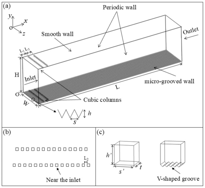 Figure 1
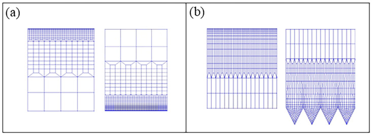 Figure 2
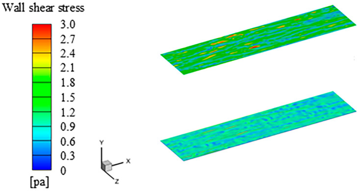 Figure 3
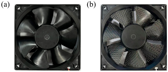 Figure 4
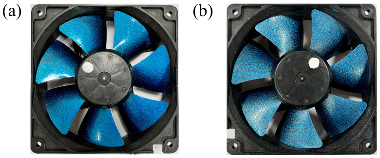 Figure 5
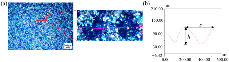 Figure 6
 Figure 7
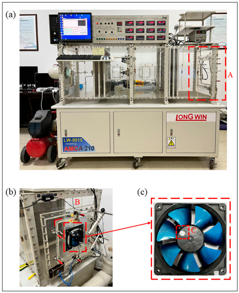 Figure 8
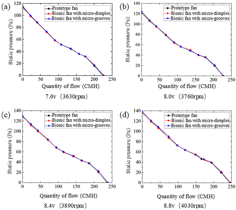 Figure 9
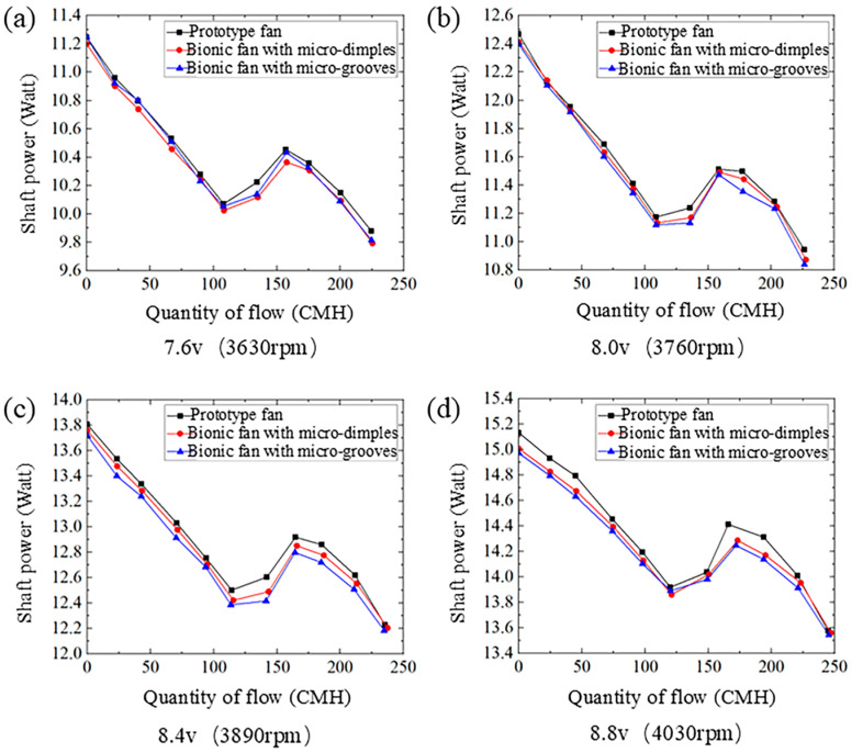 Figure 10
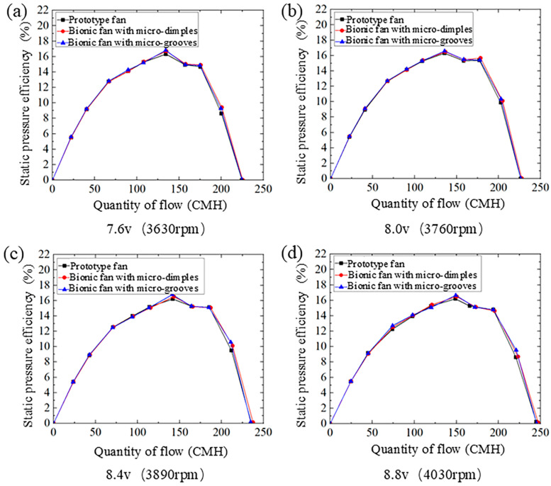 Figure 11
- —Shandong Provincial Natural Science Foundation
- —Heze University Doctoral Research Fund
- —National Natural Science Foundation of China
Peer Reviews
No public reviews on file for this paper yet. If you reviewed it on a platform where reviews are public (OpenReview, ICLR, NeurIPS, ICML), you can paste yours below so the community can read it here.
Videos
No videos yet. Explain this paper in a talk, walkthrough, or lecture? Add one.
Taxonomy
TopicsTurbomachinery Performance and Optimization · Plasma and Flow Control in Aerodynamics · Heat Transfer Mechanisms
1. Introduction
The engine is the primary power device for fluid machinery. The fan system is the core component that ensures the operational performance of the engine. As the concept of low carbon has attracted widespread attention, drag reduction and efficiency enhancement have become one of the important design goals for fan blades. Research on the aerodynamic drag reduction performance of blades includes blade structure optimization and the application of surface microstructures. The fan blade already possesses an optimized low-drag aerodynamic shape. The approach of drag reduction through blade shape modification has reached a development plateau. The method of arranging microstructures on the blade surface remains capable of achieving a certain degree of drag reduction and further improve its aerodynamic efficiency [1,2,3,4].
After years of evolution, organisms in nature have developed biological structures that are adapted to drag reduction. For instance, the surface of the shortfin mako shark (Isurus oxyrinchus) is covered with dermal denticles. The studies have clarified the correlation between scales and the main flow field around the shark, providing a biological basis for bionic drag reduction design [5]. Bionic microstructure surfaces with drag reduction effects have been developed by studying the drag-reducing characteristics of shark skin [6,7,8]. Martin and Bhushan [9] found that shark-inspired microstructures can disrupt low-intensity, large-scale vortex structures, reducing turbulent kinetic energy by approximately 15–20% and achieving a drag reduction rate of up to 8%. Bai et al. [10] studied the drag reduction characteristics of textured surfaces and indicated that micro-textures reduced surface frictional resistance by 12–18%. The bionic microstructures on the surface of blades effectively reduce the surface frictional resistance and improve the fan’s aerodynamic performance [11,12,13]. Li et al. [14] found that the micro-grooves on the blade surface increased the pump’s efficiency by 2.7% and reduced drag by 5.3%. Wang et al. [15] developed mixed flow fans with bio-inspired grooves and achieved a 4.2% increase in static pressure efficiency while reducing shaft power consumption by 3.1%. Applying a grooved film to the surface of jet engine blades, the film not only provides oxidation protection at high temperatures (up to 600 °C), but also reduces surface frictional drag by 4.5–6.2% [16]. Compared with the smooth blade, the blade with micro-dimples improves aerodynamic efficiency by 3.8% and reduces drag by 9.1% [17]. Creating a slot in the blade can control the stall of centrifugal fan flow passage, and the slotted model can also control and mitigate boundary layer separation, significantly improving the blade’s aerodynamic performance [18]. The manufacturing technologies used to produce bionic non-smooth drag-reducing surfaces mainly include casting [19,20,21,22], laser etching [23,24,25,26], chemical vapor deposition [27], milling [28], grinding [29], photolithography [30,31,32], hot embossing [33,34,35], and 3D printing [36]. The development and application of bionic microstructure drag-reducing surfaces are still limited by processing technologies. As the scale of microstructures decreases, the manufacturing cost increases significantly. Therefore, low-cost and high-efficiency bionic microstructured drag-reducing surfaces are currently a research focus in the scientific community.
In this work, the size of microstructures that can reduce drag on the blade surface is determined according to the drag reduction law of bionic micro-grooved surfaces. A drag-reducing surface with micro-dimples and micro-grooves is fabricated on the suction side of a fan blade using a spray coating technique. Aerodynamic performance tests are conducted on both prototype and bionic fan blades in wind tunnel experiments. Compared with the prototype fan, the microstructured surface of the fan blade exerts a relatively small impact on the quantity of flow–static pressure curve. The bionic fan blade consumes less shaft power, which enhances the aerodynamic performance of the fan.
2. Bionic Design on the Surface of Fan Blades
To investigate the drag reduction law of bionic micro-grooved surfaces, a calculation scheme is designed using the DOE method. A quantitative analysis of drag reduction performance is achieved through high-precision numerical simulation methods. The standard k-ꞷ model and the simpleFoam steady-state solver are employed for steady-state calculations. For unsteady calculations, the results from the steady-state calculations are used as initial values. The pimpleFoam solver and the WALE subgrid-scale model are selected to implement a transient Large Eddy Simulation (LES).
2.1. Computational Domain and Boundary Conditions
The fluid domain of the bionic micro-grooved wall and the smooth wall is presented in Figure 1. The calculation domain is the channel with different upper and lower walls. The streamwise, normal, and spanwise directions are denoted by x, y, and z, respectively. A grooved plate is distributed along the x direction of the lower wall, and the upper wall is a smooth plate. The normal height of the computational domain is set to exceed 20 times the height of the V-shaped groove, while the streamwise length is specified to be more than 30 times the groove height. This configuration is designed to avoid the negative effects of boundary conditions on the flow fields of the upper and lower walls. The height and width of the V-shaped grooves are denoted by h and s, respectively. The streamwise length L is 85 mm, the normal height H is 20 mm, and the spanwise width W is 9.75 mm. Two rows of turbulence-generating cubic columns are designed on the upper and lower walls near the inlet to trigger early transition. The sizes of the cubic columns on the upper wall and the lower wall are the same, and the V-shaped cubic columns are embedded inside the surface of the groove on the lower wall. The length s′, width t, and height h′ of single cubic column are 0.5 mm. The distance from the first row of cubic columns to the inlet (L_1_) is 3 mm, the spacing between two columns (L_2_) is 0.5 mm, the distance between the first row and the second row of the cubic column (L_3_) is 3 mm. The inlet corresponds to the given uniform velocity (5–100 m/s) and the outlet boundary condition is set as pressure. The upper and lower boundaries as well as the cubic columns correspond to the wall without slip. The boundary conditions of the periodic walls are set to be cyclicAMI.
2.2. Mesh Generation
The scale of the micro-grooved structure is extremely small, resulting in a very large number of meshes required for the computational flow field. Therefore, a layered refinement method is employed for meshing the computational model. The entire fluid domain is discretized into hexahedral meshes. In the x and z directions, the mesh is uniformly distributed, and the mesh dimensionless spacings are 7.72 and 1.64, respectively. A finer mesh must be generated in the near-wall region to accurately resolve the turbulent boundary layer. Non-uniform mesh is used in the y direction. The first layer dimensionless spacing is 0.78, which is sufficient to resolve the viscous sublayer of the flow. A Y-block division is adopted in the V-shaped groove. Figure 2 shows the grid layout near the V-shaped groove wall and smooth wall.
2.3. Grid Independence
The flow field of the grooved wall is simulated using the LES WALE subgrid-scale model at a local Reynolds number of 337,665. The drag of a grooved wall depends entirely on its surface frictional resistance. The surface friction coefficient C_f_ for turbulent flow is given by Formula (1). The three sets of meshes with different densities are designed. The mesh refinement is mainly focused on the near-wall region and the V-shaped groove structure to ensure the resolution of the turbulent boundary layer. Systematically refined grid schemes with constant refinement ratios of are applied to estimate the errors, as recommended by Wilson [37]. The surface friction coefficients of the grooved wall under three different grid schemes are compared and analyzed (Table 1). The relative error of the skin friction coefficient between Mesh 2 and Mesh 3 is only 0.186%, which demonstrates that Mesh 2 has sufficient density to accurately simulate the flow field around the micro-grooved structure.
Re_x_ is the local Reynolds number, x is the distance from the inlet, ρ is the density of air, and is the dynamic viscosity.
2.4. Drag Reduction Law of Bionic Micro-Grooved Surfaces
Figure 3 shows the wall shear stress of the smooth surface and the grooved surface at an incoming flow velocity of 20 m/s. The instantaneous drag exhibits periodic variation characteristics, and the drag reduction rate is calculated based on the time-averaged drag. D_s_ and D_r_ denote the instantaneous friction resistance of the smooth wall and the groove wall, respectively. A_s_ and A_r_ represent the areas of the smooth wall and the groove wall, respectively. DR is the rate of drag reduction, and and represent the time-averaged resistance values of the smooth surface and the groove surface, respectively. Wall shear stress of the grooved surface and the smooth surface are 4.5 × 10^−4^ pa and 4.8 × 10^−4^ pa, respectively. This indicates that the grooves exert a drag reduction effect under turbulent flow conditions, with a drag reduction rate of 6.95%.
Table 2 shows the drag reduction rates of the micro-grooved wall under different microstructural sizes and the friction Reynolds numbers. It can be concluded that the dimensionless height and width of the grooves are in the ranges of 8.50 ≤ h^+^ ≤ 29.75 and 8.50 ≤ s^+^ ≤ 29.75, and the grooved structure is drag-reducing. The dimensionless height h^+^ and dimensionless width s^+^ can be given by the following formula:
Here, is the wall friction velocity, is kinematic viscosity, is the frictional Reynolds number, and is the thickness of the turbulent boundary layer.
2.5. Determination of the Size of Bionic Microstructures on the Surface of the Fan Blade
The scales of the shortfin mako shark (Isurus oxyrinchus) have a longitudinal groove structure on the surface [5], while the cross-section of individual scales presents a micro-dimpled shape [36]. The two structural features can reduce the frictional resistance of the shark’s body during swimming. The conclusions of the bionic groove drag reduction inspired by shark skin are taken as the theoretical basis. The fan blade is approximately considered a flat plate. The size of the blade’s microstructure with a drag reduction effect is determined based on the flow field parameters of the blade.
Figure 4 shows the fan blade for testing. The voltages are 7.6 v (3630 rpm), 8.0 v (3760 rpm), 8.4 v (3890 rpm), and 8.8 v (4030 rpm) in the experiment. The flow velocity of the blade is calculated using Formula (10). The suction surface of the fan blade with microstructures is set as a rotating wall, and the rotational angular velocity is calculated using Formula (11).
Here, is the rotational angular velocity of the fan blade, r = 41.25 mm is the radius of the fan blade, and n is the rotational speed of the fan blade.
Table 3 shows the microstructure sizes of the blade surface at various voltages. The height and width ranges of the microstructures on the fan blade surface are 0.080 mm ≤ h ≤ 0.304 mm and 0.080 mm ≤ s ≤ 0.304 mm. Stainless steel mesh with a diameter of 0.30 mm is selected, and it is completely and tightly attached to the suction surface of the fan blade (Figure 4b).
3. Bionic Microstructures on Blade Surfaces
3.1. Fabrication of Microstructured Surfaces
Table 4 shows the components of the coating, sequence of configuration, and mass percentage. β-type phthalocyanine blue exhibits high crystallinity, wear resistance, stability, and strong tinting strength. It does not undergo chemical changes even at a temperature of 500 °C. The scaly structure of non-floating aluminum powder can reduce the penetration of oxygen, water vapor, and other corrosive substances. The surface of the aluminum powder slurry is coated with a layer of unsaturated fatty acid, which deposits in the middle and lower layers of the coating film under the action of gravity. Polydimethylsiloxane resin enhances the surface tension gradient within the coating, which favors the formation of surface dimples. Thus, the fabrication of surfaces featuring microstructural dimples involves the addition of polydimethylsiloxane resin. No polydimethylsiloxane is added to the coating for micro-grooves, and the mass percentage of FEVE fluorocarbon resin is increased to 67%. The bionic fan blade is presented in Figure 5.
3.2. Morphological Characteristics of Bionic Microstructured Surfaces
The morphology and size of the bionic microstructural dimples and grooves on the blade surface were measured using ultra-depth-of-field measuring equipment (VHX-6000, Keyence, Japan). The maximum resolution of the equipment is 1.3 nm and supporting 1600 × 1200 pixels. The maximum frame rate is 50 F/s. Figure 6 shows the surface of the bionic fan blade with dimple-shaped microstructures and the dimples are approximately circular or elliptical. During the curing process of the coating film, the volatilization of the solvent causes the temperature of the outer surface to drop rapidly, while the temperature inside the coating film system drops slowly. This leads to a higher surface tension on the outer layer of the coating film and a lower surface tension inside the system. It is precisely the surface tension gradient caused by the temperature gradient that drives the material in the coating film system to continuously migrate from the center of the vortex cell unit to the edge. This migration results in the depression of the vortex cell center and the bulging of the edge, and the micro-dimple structure is formed. To minimize errors arising from local variations in microstructure morphology, ten regions with areas of 1 mm^2^ were randomly selected in each blade to obtain the mean density (number of micro-dimples, mm^−2^). The mean density of the micro-dimples is 6 ± 2 mm^−2^. The depth h of the dimple ranges from 0.089 mm to 0.105 mm, and the width s is from 0.119 mm to 0.298 mm. Figure 7 presents the surface of the bionic fan blade with grooved microstructures. Both the height and width of the grooves are 0.30 mm. The fabricated micro-grooves exhibit a periodic structure with a spacing of 0.60 mm. The stainless steel mesh is aligned parallel to the streamwise direction of the blade’s suction surface and the alignment is consistent with the dominant flow direction of the blade surface.
4. Experimental Investigation of the Aerodynamic Performance of Bionic Fan Blades
4.1. Methods
The aerodynamic performance of the prototype and bionic fan blades was tested using the fully automatic air flow and pressure measuring equipment (LW-9015-250, Taiwan, China) shown in Figure 8a. Region A denotes the position of the wind tunnel end plate. The flow rate range of the equipment is 2.4–250 CFM. The static pressure range is 0–120 mmAq. The accuracy of voltage and current is ±0.5%, and the accuracy of rotational speed is ±1.0%. The maximum diameter of the tested fan is 140 mm. The constant voltage mode was adopted in the fan test. The tested fan installed at the wind tunnel port is shown in Figure 8b. Region B is the fan installation position. Figure 8c shows the tested bionic fan. A laser is aligned with the reflective sticker (test point C) to measure the rotational speed of the fan blades. The distance between the laser and the reflective sticker is about 20 cm. The aerodynamic performance of the prototype and bionic fan blades was tested at different rotational speeds, under the condition of a stable external wind field. The fully automatic air flow and pressure measurement wind tunnel is controlled by a fully automated computer system, which enables the acquisition of the flow rate–static pressure curve, flow rate–shaft power curve, and flow rate–static pressure efficiency curve of the fan blade. The static pressure efficiency (η_es_) of the fan is determined by the effective static pressure power (N_e_) and the input shaft power N.
Here, Q is the flow rate and P_s_ denotes the static pressure.
4.2. Results and Discussion
4.2.1. Quantity of Flow–Static Pressure Curve
Figure 9 shows the quantity of flow–static pressure curves of the prototype fan and the bionic fans under four different rotational speeds. The quantity of flow–static pressure curves for the prototype and bionic fans exhibit the same trend. As the quantity of flow increases, the static pressure decreases gradually. There are slight differences in the maximum static pressure and maximum flow rate between the prototype fan and the bionic fans. The compared values between the prototype fan and the bionic fan are shown in Table 5. At a rotational speed of 3630 rpm, the maximum static pressure of the bionic fan with micro-dimples increases by 1.23% compared to the prototype fan. At 3760 rpm, the maximum increase in maximum static pressure of the bionic fan with micro-grooves compared to the prototype fan is 2.36%. Under the rotational speeds of 3890 rpm and 4030 rpm, the increases in maximum flow rate of the bionic fan with micro-dimples relative to the prototype fan are quite similar, at 0.89% and 0.90%, respectively. The bionic fan with micro-grooves exhibits a maximum flow rate enhancement of 1.41% over the prototype fan. The two bionic structures on the blade surface exert a relatively small influence on the quantity of flow–static pressure curve of the fan.
4.2.2. Quantity of Flow–Shaft Power Curves
Figure 10 shows the quantity of flow–shaft power curves of the prototype and the bionic fans under four different rotational speeds. The quantity of flow–shaft power curve exhibits an initial decrease, followed by a rise and a subsequent decrease. Both bionic fans require less shaft power than the prototype. The shaft power consumed by the fan increases as the rotational speed rises. Table 6 lists the shaft power at the maximum flow rate for both the prototype and bionic fans. At a rotational speed of 3630 rpm, the bionic fan with micro-dimples consumes the lowest shaft power compared to the prototype fan. Its relative value is −0.92%. Under the rotational speed of 3760 rpm, a 1.01% reduction in shaft power consumption is observed for the micro-grooved bionic fan relative to the prototype fan.
4.2.3. Quantity of Flow–Static Pressure Efficiency Curves
Figure 11 shows the quantity of flow–static pressure efficiency curves of the prototype fan and the bionic fans under four different rotational speeds. With increasing flow rate, the static pressure efficiency follows a trend of an initial increase, followed by a decrease, a minor recovery, and a final decline to zero. There is a maximum point of static pressure efficiency within the flow rate. Table 7 presents the maximum static pressure efficiency, error, and efficiency improvement for both the prototype and bionic fans. At a rotational speed of 3630 rpm and a flow rate of 134 CMH, the bionic fan with dimples achieves the largest increase in maximum static pressure efficiency, and its relative value is 2.33%. The maximum static pressure efficiency of the bionic fan with micro-grooves reached its highest increase of approximately 3.46% at a rotational speed of 3890 rpm and a flow rate of 148 CMH. The maximum static pressure efficiency of the bionic fans is higher than that of the prototype fan, which indicates that the application of dimple or groove structures on the blade surface enhances aerodynamic efficiency.
5. Conclusions
The scales on a shark’s body are characterized by a longitudinal groove structure. The cross-section of an individual scale resembles the curve of a dimple. The rapid and efficient fabrication of on-demand controllable micro-dimpled or micro-grooved surfaces on the suction side of fan blades is achieved based on the structural features of shark scales. For microstructural dimensions ranging from 0.080 mm to 0.304 mm in both height and spacing, the bionic fan blade may enhance aerodynamic efficiency, thereby enabling drag reduction. The spraying process was used to fabricate micro-dimples with a depth of 0.089–0.105 mm and a width of 0.119–0.298 mm, and micro-grooves with both height and width of 0.30 mm. A wind tunnel study was carried out to assess the aerodynamic performance of both the prototype and bionic fan blades. The presence of micro-dimple and micro-groove structures had a minor effect on the flow–static pressure curve of the fan. Compared to the prototype fan, the bionic fan blades consumed less shaft power and achieved higher maximum static pressure efficiency. This indicates that the microstructures of the surface disrupt low-intensity vortex structures and reduce turbulent kinetic energy. Under a rotational speed of 3630 rpm, the bionic fan with micro-dimples achieved a 2.33% relative improvement in maximum static pressure efficiency. The maximum static pressure efficiency of the micro-grooved bionic fan increased by 3.46% at 3890 rpm. This improvement in static pressure efficiency is consistent with the performance of bionic micro-textured surfaces reported in centrifugal pumps [14] and aero-engine blades [16], confirming that bionic microstructures can effectively optimize the aerodynamic performance of small axial flow fans. At 3760 rpm, the micro-grooved bionic fan exhibits the lowest shaft power consumption, with a relative value of 1.01% compared to the prototype fan. The microstructures on the blade surface enhance the aerodynamic performance of the fan, reducing drag and improving efficiency. In the future, the combination of macro blade shape optimization and microstructural surfaces can be used to achieve synergistic drag reduction and efficiency improvement.
The reference list from the paper itself. Each links out to its DOI / PubMed record.
- 1Büttner C.C. Schulz U. Shark skin inspired riblet coatings for aerodynamically optimized high temperature applications in aeroengines Adv. Eng. Mater.20111328829510.1002/adem.201000265 · doi ↗
- 2Liu Y. Yuan Q. Optimizing Bionic Blades for Multi-blade Centrifugal Fans: Asymmetric Thickness Inspired by Carangiform Fish J. Appl. Fluid Mech.2024171735357210.47176/jafm.17.11.2711 · doi ↗
- 3Zhu Q. Zhang C. Yu F.H. Xu Y. Investigation on drag reduction on rotating blade surfaces with microtextures Beilstein J. Nanotechnol.20241583385310.3762/bjnano.15.7039021505 PMC 11252563 · doi ↗ · pubmed ↗
- 4Zhang W. Yu D.H. Li G.C. Zhao C.Y. Liu Z.N. The mechanisms of drag reduction through bionic microstructures on fan blade surfaces Phys. Fluids 20253702519010.1063/5.0253212 · doi ↗
- 5Zhang C.C. Gao M.H. Liu G.Y. Zheng Y.H. Xue C. Shen C. Relationship Between Skin Scales and the Main Flow Field Around the Shortfin Mako Shark Isurus oxyrinchus Front. Bioeng. Biotechnol.20221074243710.3389/fbioe.2022.74243735547174 PMC 9081372 · doi ↗ · pubmed ↗
- 6Zhang K.S. Li J. Zhang K.Z. Zhang J. Optimization of surface microgrooves and their performance and mechanism of synergistic drag reduction with bionic mucus Ocean. Eng.20253170029801810.1016/j.oceaneng.2024.120029 · doi ↗
- 7Wang Y.M. Lu C.J. Cui C.H. Lu W.J. Sun J.Y. Fan J.J. Zhang Y.F. A review of research on drag reduction and energy-saving of non-smooth biomimetic structure and its application Mater. Today Commun.2025482352492810.1016/j.mtcomm.2025.113429 · doi ↗
- 8Heidarian A. Ghassemi H. Liu P. Numerical analysis of the effects of riblets on drag reduction of a flat plate J. Appl. Fluid Mech.20181167968810.29252/jafm.11.03.28344 · doi ↗