CT/MRI-based finite element model construction and biomechanical analysis of acetabular quadrilateral fractures
Jieyu Chen, Huawu Liu, Lei Bai, Sergei V. Petrenko, Chaohui Wang, Jianhui Yan, Yonglin Ge

TL;DR
This study uses CT/MRI data to create a biomechanical model of acetabular fractures and compares the effectiveness of different surgical fixation techniques.
Contribution
The paper introduces a finite element model of acetabular quadrilateral fractures and evaluates the biomechanical performance of combined fixation techniques.
Findings
Combined posterior column and quadrilateral buttress screws fixation showed the best mechanical stability.
Fracture displacement was highest in the unfixed group under all loading conditions.
Peak stress locations varied depending on the fixation method and loading condition.
Abstract
The study aims to construct a representative acetabular quadrilateral fracture model and compare the biomechanical performance of three internal fixation techniques. CT data from 70 fractures were analyzed to create fracture line mappings. A finite element model incorporating ligaments, cartilage, and fracture lines was developed using CT/MRI data from a healthy volunteer. Five loading conditions (standing, supine, lateral lying, sitting, femoroacetabular impingement) were simulated. Four groups were compared: unfixed (Group A), posterior column screw fixation (Group B), quadrilateral buttress screws fixation (Group C), and combined posterior column and quadrilateral buttress screws fixation (Group D). The most frequent fractures were both-column and anterior wall fractures. Fracture line displacement under standing conditions was Group A > Group B > Group C > Group D. In other…
Genes, proteins, chemicals, diseases, species, mutations and cell lines named across the full text — each resolved to its canonical identifier and authoritative record.
Click any figure to enlarge with its caption.
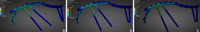 Figure 10
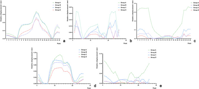 Figure 11
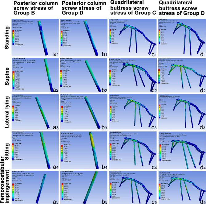 Figure 12
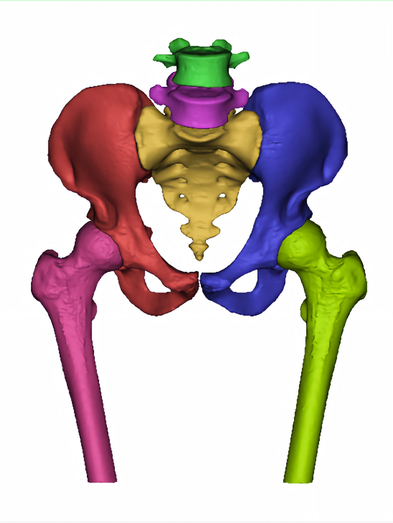 Figure 1
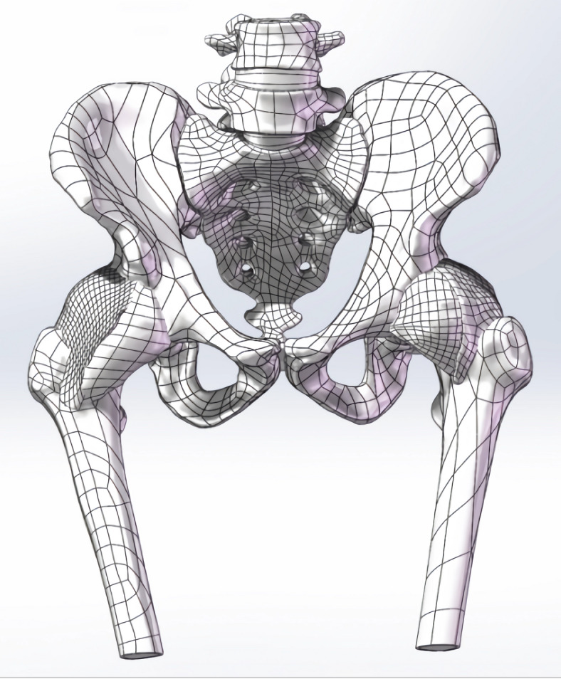 Figure 2
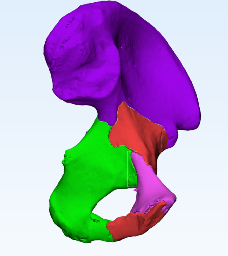 Figure 3
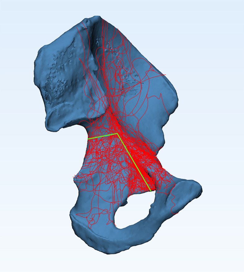 Figure 4
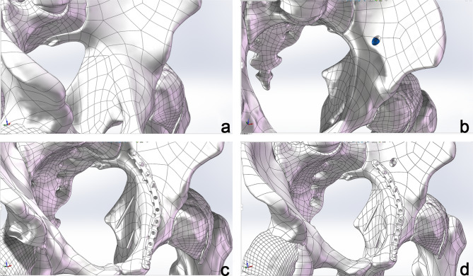 Figure 5
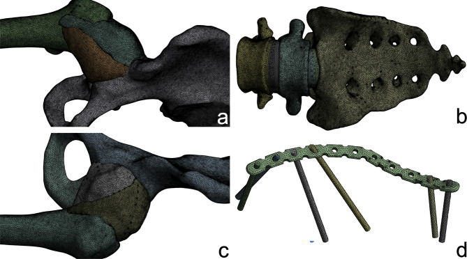 Figure 6
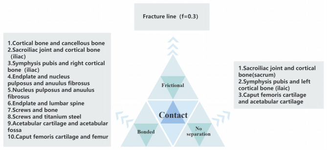 Figure 7
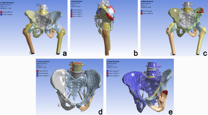 Figure 8
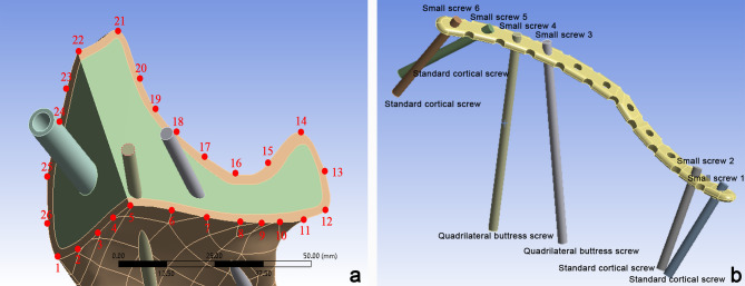 Figure 9
- —Xiangnan School -level Scientific Research Project
- —Chenzhou Technology Research and Development Center in 2021
- —Hunan Provincial Natural Science Foundation of China
Peer Reviews
No public reviews on file for this paper yet. If you reviewed it on a platform where reviews are public (OpenReview, ICLR, NeurIPS, ICML), you can paste yours below so the community can read it here.
Videos
No videos yet. Explain this paper in a talk, walkthrough, or lecture? Add one.
Taxonomy
TopicsPelvic and Acetabular Injuries · Hip disorders and treatments · Orthopaedic implants and arthroplasty
Introduction
Acetabular fractures account for approximately 0.8% of all fractures, with a higher incidence in females than in males^1^. With the increasing development of transportation and growing aging population, the incidence of acetabular quadrilateral plate fractures has been steadily rising. For unstable quadrilateral plate fractures, the primary clinical treatment involves open reduction and internal fixation. Commonly employed fixation methods include posterior column screws, quadrilateral buttress screws, and a combination of both. Due to the deep anatomical location of the acetabulum and the thin medial wall of the quadrilateral plate, adjacent to critical neurovascular structures, quadrilateral fractures are frequently comminuted, making anatomical reduction challenging. Improper screw placement risks breaching the articular cavity^2,3^. Consequently, selecting an appropriate fixation strategy remains a crucial topic in orthopedic research.
Fracture mapping is a computational approach that overlays multiple fracture lines onto a standardized model, facilitating a visual representation of fracture trajectories and distributions. This technique has been extensively utilized for Pilon fractures, tibial plateau fractures, and proximal humeral fractures^4^. Finite element analysis (FEA) is a numerical method that discretizes a structure into smaller elements to simulate and solve physical problems mathematically. It has become a well-established tool in fracture treatment, implant design validation, and surgical planning^5–8^. Currently, there is no relevant research on using fracture line mapping to plot high-frequency fracture lines of the acetabulum and combining finite element analysis to explore the fixation effects of different internal fixation methods on these fracture lines. Hereby, this study retrospectively analyzed CT data from 70 patients with acetabular fractures to generate a fracture mapping and identify common fracture patterns. A representative quadrilateral fracture model was then constructed based on CT and MRI data from a healthy adult male. Using finite element modeling, we evaluated the biomechanical performance of three common internal fixation techniques under five different loading conditions: standing, supine, lateral lying, sitting, and femoroacetabular impingement. The objective was to provide clinical recommendations for the optimal fixation strategy for quadrilateral plate fractures.
Materials and methods
Patient selection and data collection
A retrospective analysis was conducted on 70 cases of acetabular fractures from December 2020 to December 2023 at The Affiliated Hospital of Xiangnan University and The First Affiliated Hospital of Xiangnan University. Among participants, 50 were male, and 20 were female, with an age range of 14 to 86 years (mean age: 47.66 ± 16.09 years). The inclusion criteria comprised pure acetabular fractures and high-resolution CT scans with slice spacing ≤ 2.0 mm and thickness ≤ 2.7 mm. The exclusion criteria included diagnosed acetabular deformities or dysplasia, incomplete closure of acetabular epiphyseal plates, a history of acetabular surgery, and poor-quality CT images with unclear boundaries. This study was approved by the Medical Ethics Committee of The Affiliated Hospital of Xiangnan University (Approval No. K2024-008-01). All procedures were performed in accordance with the Declaration of Helsinki and relevant guidelines and regulations. Written informed consent was obtained from all participants.
Healthy volunteer CT and MRI data acquisition
A 21-year-old adult male volunteer ( weight: 60 kg, height: 178 cm) with no history of lumbar, pelvic, or hip joint disorders was recruited. CT scanning was performed using a 256-slice spiral CT scanner while the volunteer was supine, capturing 2,993 slices with a thickness of 0.63 mm. MRI scanning was conducted with a Signa HDx 3.0T MRI scanner, covering the pelvis, bilateral proximal femurs, and L_4_/L_5_ vertebrae, producing 50 slices with a thickness of 1.3 mm.
Development of the lumbar-pelvis-hip joint 3D model
Mimics Medical 14.0 (Materialise, Belgium) was employed for the three-dimensional reconstruction of pelvic structures, including the lumbar spine, pelvis, and femoral structures based on CT imaging (Fig. 1). In contrast, the pubofemoral, iliofemoral, and ischiofemoral ligaments were analyzed using MRI (Fig. 2). The software 3-matic was utilized for the repositioning of fractured bone fragments in 70 cases of acetabular fractures (Fig. 3). Additionally, Adobe Photoshop 2018 (Adobe Systems, USA) was used to manually map fracture lines onto the reference model and to design typical fracture lines (Fig. 4), facilitating the visualization of common patterns and the identification of quadrilateral plate-involved fractures.
Fig. 1. Three-dimensional modeling of lumbar spine-pelvis-hip joint bony structure.
Fig. 2. Three-dimensional solid model of lumbar spine-pelvis-hip joint containing soft tissue.
Fig. 3. Schematic diagram of bone block repositioning in a patient with acetabular quadrilateral body fracture.
Fig. 4. Schematic diagram of the typical fracture line.
Smoothing and refinement of the pelvic model were conducted using Geomagic Wrap 2021 (Geomagic, USA). To distinguish between cortical and cancellous bone, the cortical layer was offset 2 mm inward. The design of the cartilage structures and internal fixation devices was completed using SOLIDWORKS 2023 (SolidWorks, USA). For the typical fracture line that we designed, we established four experimental groups to compare the effects of internal fixation (Fig. 5). The groups are as follows: an unfixed group (Group A), a posterior column screw fixation group (Group B), quadrilateral buttress screws fixation group (Group C), and a combined posterior column and quadrilateral buttress screws fixation group (Group D). The details of the fixation are as follows: quadrilateral buttress screws (diameter: 3.5 mm, length: 80 mm); standard cortical screws (diameter: 3.5 mm, length: 40 mm); posterior column hollow screws (diameter: 7.3 mm, length: 100 mm, thickness: 1.15 mm).
Fig. 5. Schematic diagram of Groups A, B, C and D. (a) unfixed group; (b) a posterior column screw fixation group; (c) quadrilateral buttress screws fixation group; (d) combined posterior column and quadrilateral buttress screws fixation group.
FE model establishment and material property setting
We utilized ANSYS 17.0 (ANSYS, USA) for finite element analysis and post-processing. The model was imported into ANSYS and characterized as an isotropic linear material based on values from the literature^1,9–13^. Ligament stiffness coefficients were assigned as specified in Table 1. Ligaments were modeled as linear isotropic elastic materials or springs. It is acknowledged that this is a simplification of their tension-only biological behavior, which may introduce artificial stiffening under compressive loads. To verify the mesh independence of the computational results and optimize computational resources, a mesh convergence analysis was conducted. Models with global sizes of 3 mm, 2 mm, and 1 mm were compared, revealing that the stresses in the internal fixation devices and key bony regions such as the acetabulum and sacrum were more sensitive to mesh density. Consequently, a hybrid mesh strategy with local refinement was adopted: the sacrum, lumbar spine, left ilium (cortical and cancellous bone), and internal fixation devices were discretized with 1.0 mm tetrahedral elements, while all other bony structures, cartilage, and ligaments were assigned a 2.0 mm element size (Fig. 6). The final mesh quality varied among the different groups: Group A included 2,257,270 elements and 3,960,161 nodes; Group B comprised 2,285,474 elements and 4,011,568 nodes; Group C contained 2,294,378 elements and 4,028,962 nodes; and Group D consisted of 2,323,101 elements and 4,081,141 nodes.
Table 1. Material properties of each part^1,9–13^.MaterialsYoung’s modulus(MPa)Poisson’s ratio(%)Stiffness coefficient K (N/mm)Cartilage (symphysis pubis)50.45–Cartilage (sacroiliac joint)540.4–Cartilage (Acetabular cartilage)120.42–Cartilage (caput femoris cartilage)10.50.3–Titanium steel114,0000.3–Cortical bone (iliac)17,0000.3–Cancellous bone (iliac)1320.2–Cortical bone (sacrum)61400.3–Cancellous bone (sacrum)14000.3–Cortical bone (femur)12,0000.3–Cancellous bone (femur)1000.3–Cortical bone (Lumbar spine)12,0000.3–Cancellous bone (Lumbar spine)3450.2–Anuulus fibrosus550.3–Nucleus pulposus10.495–Endplate10000.4 –Ischiofemoral ligament99.50.4–Pubofemoral ligament980.4–Iliofemoral ligament113.30.4–Sacrospinous ligament––1400Sacrotuberous ligament––1500Sacroiliac anterior ligament––700Sacroiliac posterior ligament––1000Inguinal ligament––250Iliolumbar ligament––1000
Table 270 cases of acetabular fractured patients characteristics.Patient characteristicsn = 70Age47.66 ± 16.09Gender Male50 (71%) Female20 (29%)Side of injury Left43 (61%) Right27 (39%)Letournel classification Simple fracture Anterior wall fracture17 (24%) Posterior wall fracture2 (3%) Anterior column fracture4 (6%) Posterior column fracture1 (1%) Transverse fracture8 (11%)Complex fracture T-shaped fracture4 (6%) Posterior column and posterior wall fractue4 (6%) Anterior column and anterior wall fractue2 (3%) Anterior column and posterior hemi-transverse fracture6 (9%) Transverse and posterior wall fractue5 (7%) Both-column fracture17 (24%)Lesion mechanism Low-energy truma27 (39%) Traffic accident36 (51%) Fall from height4 (6%) Injured by weight2 (3%)Hurt by somebody1 (1%)
Fig. 6. Mesh division diagram. (a) Right hip joint; (b) sacrum and lumbar spine; (c) left hip joint; (d) internal fixation.
Contact interactions were defined (Fig. 7), and five physiological loading conditions were simulated (Fig. 8). In the standing condition, both femoral distal ends were constrained, and a vertical force of 500 N was applied at L_4_. For the supine condition, the bilateral iliac crests were constrained, with a force of 250 N applied to the anterior iliac crest. In the lateral lying condition, both femoral distal ends were constrained, and a horizontal force of 500 N was applied to the iliac crest. During the sitting condition, both femurs were constrained, and an axial force of 500 N was applied at L4. Lastly, for femoroacetabular impingement, both femurs were constrained, and a force of 500 N was applied to the acetabular fossa in the direction of the femoral neck.
Fig. 7. Contact adjustment chart.
Fig. 8. Five groups of working conditions simulation setup diagram. (a) Standing; (b) Supine; (c) Lateral lying; (d) Sitting; (e) Femoroacetabular impingement.
Main observation indicators
The key observational indicators include the relative displacement along the fracture line and the stress distribution of the fixation system. Specifically, 26 points were selected at the intersections of two fracture lines, with intervals of 5 to 10 mm along the fracture path (Fig. 9a). The relative displacement was determined by calculating the difference between the maximum and minimum displacements. Additionally, the maximum equivalent von Mises stress and its distribution were analyzed for both the internal fixation device and the small screws (1–6) to evaluate their mechanical performance (Fig. 9b).
Fig. 9. Schematic diagram of point selection and screw naming. (a) Schematic of the 26 point selections; (b) Schematic of the small screws.
Statistical analysis
Fracture displacement data were transformed using square root normalization and analyzed using one-way ANOVA in SPSS 26.0. Data were reported as Mean ± standard deviation (SD), with P < 0.05 considered statistically significant.
Results
Acetabular fracture classification and distribution
A total of 70 acetabular fracture cases were analyzed, comprising 43 fractures on the left side and 27 on the right. According to the Judet-Letournel classification, the most prevalent fracture types were anterior wall fractures and both-column fractures, each accounting for 24% of the cases (Table 2). Fracture mapping (Fig. 4) revealed that the highest-density fracture zones were located at the arcuate line and the pubic obturator edge, with the eminentia iliopectinea being the most frequently fractured site. This phenomenon may be attributed to the annular structure of the pelvis, which primarily transmits forces from the lumbar spine, rendering the arcuate line particularly susceptible to injury. Furthermore, the structurally weaker iliopubic ramus, which connects the pubic bone to the ilium, is highly vulnerable to fractures resulting from femoral impingement forces. The second highest fracture density is observed between the middle of the greater sciatic notch and the arcuate line, while fractures extending from the sciatic spine to the lower border of the quadrilateral plate are distributed more sparsely. This distribution indicates that the posterior column, particularly its upper region, is more prone to fractures when the femoral head impacts obliquely upward, either due to high-energy trauma or low-energy falls.
Mesh convergence analysis
To verify the mesh independence of the computational results, a systematic mesh convergence analysis was conducted on key mechanical parameters, with the convergence criterion defined as a variation of less than 5% in critical outputs after successive mesh refinements. The maximum equivalent von Mises stress in the internal fixation was recorded as 14.011 MPa at a mesh size of 3.0 mm, 15.822 MPa at 2.0 mm, and 15.816 MPa at 1.0 mm, with a negligible variation of less than 0.04% between the 2.0 mm and 1.0 mm configurations (Fig. 10). The mean and standard deviation of fracture line relative displacements were 0.003 ± 0.002 mm at 3.0 mm, 0.004 ± 0.003 mm at 2.0 mm, and 0.004 ± 0.003 mm at 1.0 mm, showing consistent values between the 2.0 mm and 1.0 mm mesh configurations. Under a 500 N load, the overall mechanical response of the model remained consistent; although mesh refinement captured more localized deformations, the computed displacements exhibited reasonable and continuous variation without abnormal fluctuations, indicating controllable and predictable global mechanical behavior. These results confirm that the adopted mesh configuration demonstrates adequate convergence.
Fig. 10. The maximum equivalent von Mises stress diagrams for internal fixtures under three FEA meshing conditions. (a) 3 mm; (b) 2 mm; (c) 1 mm.
Fracture line displacement
The relative displacement of the fracture line under standing conditions exhibited a clear trend: Group A > Group B > Group C > Group D (F = 216.744, P < 0.01) (Fig. 11a). In the remaining four conditions: supine (F = 220.641, P < 0.01), lateral lying (F = 196.204, P < 0.01), sitting (F = 205.071, P < 0.01), and femoroacetabular impingement (F = 213.206, P < 0.01), the displacement pattern was Group A > Group C > Group B > Group D (Fig. 11b–e).
Fig. 11. Relative displacement of fracture line paths for five groups of working conditions fracture line plot. (a) Standing; (b) supine; (c) lateral lying; (d) sitting; (e) femoroacetabular impingement.
Maximum equivalent von mises stress on fixation devices
Posterior column screws
Under supine loading, Group D exhibited higher stress levels than Group B (Fig. 12-a_2_, b_2_). However, in the remaining conditions, Group B demonstrated greater stress than Group D (Fig. 12-a_1_, a_3 − 5_, b_1_, b_3 − 5_).
Fig. 12. The maximum equivalent von Mises stress diagrams for internal fixtures under five operating conditions. (a1–5), posterior column screw stress of Group B; (b1–5), posterior column screw stress of Group D; (c1–5), quadrilateral buttress screws and plate stress of Group C; quadrilateral buttress screws and plate stress of Group D; (a1–d1), standing; (a2–d2), Supine; (a3–d3), lateral lying; (a4–d4), sitting; (a5–d5), femoroacetabular impingement.
Quadrilateral buttress screws
In the lateral lying position, Group D experienced higher stress than Group C (Fig. 12-c_3_, d_3_), while Group C exhibited greater stress in the other four conditions (Fig. 12, c_1 − 2_, c_4 − 5_, d_1 − 2_, d_4 − 5_).
Cortical screws fixed via plates
Across all conditions, posterior column screws endured greater stress than anterior screws, with the highest stress levels recorded in screws 5 and 6 (Table 3).
Table 3. The maximum Von-mises stress of common screws (MPa).GroupScrewPostureStandingSupineLateral lyingSittingFemoroacetabular impingementGroup CC_1_13.2942.308622.1852.50711.159C_2_12.7461.862412.3758.502411.566C_5_14.9059.562554.58220.63229.78C_6_22.19514.29105.89035.5248.487Group DD_1_10.5302.096331.8783.342611.439D_2_8.9291.607420.2875.208611.943D_5_13.9718.217236.18219.12723.568D_6_25.52112.50976.54636.64949.087
Discussion
The acetabular quadrilateral plate, the “third column” alongside the anterior and posterior columns, is essential for maintaining normal weight-bearing function^14^. According to the Clinical Diagnosis and Treatment Guidelines for Acetabular Quadrilateral Plate Fractures (2023)^3^, fixation strategies involve either partially or completely blocking the quadrilateral plate after stabilizing the anterior and posterior columns using a “frame” structure. Various internal fixation devices have been designed and analyzed through finite element methods, including periacetabular channel screws^15^, dynamic anterior plating systems^16^, customized 3D-printed blocking plates^17^, and specialized quadrilateral plate-integrated anatomical plates^9,18^. However, no standardized treatment protocol currently exists, and most approaches depend on clinical experience. This study utilized CT and MRI data from a healthy volunteer to construct a three-dimensional finite element model, comparing the mechanical characteristics of an unfixed group with three fixation methods under five loading conditions.
Fracture line mapping technology has been extensively applied to analyze fracture distributions, aiding in classification refinement, surgical planning, internal fixation design, and finite element validation, while providing a theoretical foundation for surgical optimization^4,19,20^. Although previous studies have characterized acetabular fractures using this technique^19^, dedicated investigations into quadrilateral plate fractures remain lacking. This study analyzed CT data from 70 cases of acetabular quadrilateral plate fractures to construct a fracture line map, classifying cases using the Judet-Letournel system to identify high-incidence patterns and distribution trends. The findings indicate that both-column and anterior wall fractures are the most prevalent. A study of 3,346 acetabular fractures reported a 21.2% incidence of both-column fractures^21^, which aligns with this study’s findings (17/70, 24%). Traffic accidents emerged as the predominant injury mechanism, likely due to the characteristic pathophysiology of both-column fractures, where forceful anterior and medial femoral head impact against the acetabular medial wall results in complete dissociation from the axial skeleton. While anterior wall fractures are less common, they are associated with poorer prognostic outcomes^22^ and their higher incidence in this study may be attributable to limitations in sample size.
Finite element analysis demonstrated that the unfixed group (Group A) exhibited the greatest displacement of the fracture line among the five conditions, thereby validating the reliability of the fixation models, consistent with the findings of Fan et al.^23–25^. In contrast, Group D exhibited the minimum displacement, indicating that the combined fixation using posterior column screw and quadrilateral buttress screws provides superior stability. In the standing position, quadrilateral buttress screws fixation (Group B) outperformed posterior column screw fixation (Group C). However, under other conditions, the posterior column screw provided enhanced stability. These findings suggest that posterior column screws effectively mitigate displacement under various loads and should be prioritized for internal fixation, preferably in combination with quadrilateral buttress screws. Furthermore, early postoperative standing and weight-bearing should be minimized, especially for patients fixed with quadrilateral buttress screws, in accordance with Oldhoff et al.^26^, although this approach differs from the recommendations of Berk et al.^27^.
The stability of internal fixation devices is closely related to their maximum equivalent Von Mises stress, with peak stress serving as a key indicator of fixation reliability. Finite element analysis revealed that, except in the supine condition, the posterior column screw in Group B exhibited higher peak stress than that in Group D across four loading conditions, suggesting improved stress distribution and enhanced fixation stability. However, in the supine condition, Group D demonstrated higher peak stress, indicating that quadrilateral buttress screws provide limited resistance to forces at the anterior superior iliac spine level. For quadrilateral buttress screws, peak stress was higher in Group D than in Group C under the lateral lying condition, while in other conditions, Group C exhibited higher stress, suggesting that both fixation methods contribute to stability in this position. Mechanically, plate fixation prevents displacement but lacks angular cross-fixation, whereas posterior column screws provide axial compression and resist shear and torsional forces, although they may not fully prevent fragment displacement when used alone. Combined fixation effectively counteracts multidirectional fragment displacement and enhances overall stability. Based on these findings, the combined use of posterior column screws and quadrilateral buttress screws is recommended as the preferred internal fixation strategy.
The maximum equivalent von Mises stress of small screws represents their fixation strength, with higher peak stress indicating better stability when screw length, diameter, and material remain constant. Across all five loading conditions, cortical screws 5 and 6 consistently exhibited higher peak stress than screws 1 and 2, suggesting that their fixation effect was significantly superior. This may be attributed to the designed fracture line in this study, which primarily involved the acetabular quadrilateral plate and was more concentrated along the posterior column. In light of these findings, it is recommended that clinicians position acetabular peripheral screws closer to the fracture line when applying fixation with a plate. Additionally, depending on intraoperative conditions, increasing the number of screws near the sacroiliac joint may be considered to enhance overall fixation stability.
This study developed a relatively comprehensive finite element model of the lumbar-pelvis-hip joint complex through systematic integration of CT and MRI imaging data. The model reconstruction maintained anatomical continuity by incorporating major solid ligaments and cartilaginous structures, which demonstrated reasonable agreement with actual anatomical features. Based on the analysis of 70 clinical CT cases, a representative fracture line pattern for the acetabular quadrilateral plate was established, thereby improving the clinical relevance of the simulation results. The study evaluated five key rehabilitation postures including standing, sitting, supine, lateral lying, and femoral head impaction, enabling systematic assessment of biomechanical responses under various physiological loading conditions. This integrated methodology provides valuable multi-modal mechanical insights to support clinical rehabilitation strategies, effectively balancing anatomical accuracy with practical clinical applicability.
Several methodological considerations should be noted when interpreting our findings. First, both soft tissues and bony structures were modeled as linear isotropic elastic materials to ensure computational tractability. While this established simplification offers computational efficiency, it inherently does not capture the anisotropic nature of bone or the nonlinear and tension-only properties of biological tissues. Second, a deliberate hybrid modeling strategy was adopted for the ligaments. Specifically, certain ligaments critical for global joint stability were modeled as 3D volumetric solids to preserve their anatomical geometry, while others were represented as spring elements for simplification. It is acknowledged that this pragmatic approach, despite its rationale, may introduce variability and influence the mechanical predictions. Third, potential geometrical inaccuracies could arise from the manual mapping of fracture lines. Finally, the model did not incorporate the effects of surrounding muscles and synovial fluid, thus simplifying the dynamic simulation. Despite these limitations, the current framework provides a valuable and computationally viable method for initial biomechanical investigation. Future work will prioritize the use of computer-generated fracture heatmaps and the implementation of more sophisticated nonlinear material models to enhance biomechanical fidelity.
Conclusion
To sum up, this biomechanical study suggests that posterior column screw combined with quadrilateral buttress screws fixation may provide superior mechanical stability and could be considered as a preferred option for the clinical fixation of acetabular quadrilateral fractures, pending further clinical validation. Moreover, it is recommended to place cortical bone screws applied through the plate close to the fracture line, and the number of screws may be increased on the side of the sacroiliac joint according to the actual situation. Additionally, based on the current biomechanical findings, early postoperative weight-bearing is not advised.
The reference list from the paper itself. Each links out to its DOI / PubMed record.
- 1Chinese Orthopaedic Association, The Group of Pelvic & Acetabular, Chinese Association of Onhopaedic, The Group of Pelvie &Acetabular Injury, Orthopaedic Branch, China Intermational Exchange and Promoive Association for Medical and Healh Care, The Pelvis & Acetabular Group of the Orthopaedics & Traumatology Professional Commitee of Hubei Associanion of Chinese Medicine, Clinical guideline for the diagnosis and treatment of quadrilateral plate fractures of acetabulum Chin. J. Bone Joint Surg.16,
- 2Sen, R. K. et al. Acetabular fracture in India: An epidemiological study. J. Clin. Orthop. Trauma.56. 10.1016/j.jcot.2024.102540 (2024).10.1016/j.jcot.2024.102540 PMC 1142214139328296 · doi ↗ · pubmed ↗