Influence of different customized abutment materials on stress distribution of different internal implant-abutment connections: finite element analysis
Ahmed Ziada, Marwa Beleidy

TL;DR
This study uses 3D modeling to analyze how different abutment materials and implant-abutment connections affect stress distribution in dental implants under various loading conditions.
Contribution
The study introduces a comparative finite element analysis of two implant-abutment connection designs with four abutment materials under axial and oblique loading.
Findings
Titanium abutments showed the lowest stress values across different loading conditions.
Oblique loading produced cortical strains above safe limits, while axial loading had lower stress values.
Both connection types caused minimal screw deformation, indicating low loosening risk.
Abstract
Limited research evaluates how the type of implant-abutment connection and the material of the abutment together affect the biomechanical behavior of load transfer within both the implant components and the surrounding bone under axial and oblique loading conditions. This 3-dimensional (3D) finite element analysis (FEA) study aimed to provide biomechanical insights to assist clinicians in choosing optimal connection designs and abutment materials, enhancing implant longevity and clinical outcomes. Two internal implant-abutment connections were modeled in 3D: model (S), which is a star-shaped tube-in-tube design, and model (H), which is a Morse taper combined with an internal hex, both intended to support a mandibular first molar crown and its associated bone geometry. Four abutment materials (Titanium grade V/Ti, Co-Cr, soft-milled Co-Cr–Mo/Co-Cr-S, and zirconia/Zr) were examined using…
Genes, proteins, chemicals, diseases, species, mutations and cell lines named across the full text — each resolved to its canonical identifier and authoritative record.
Click any figure to enlarge with its caption.
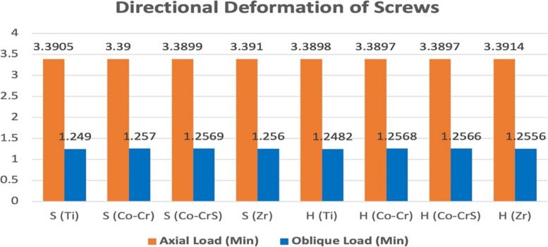 Figure 10
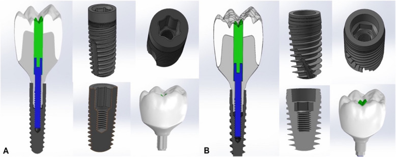 Figure 1
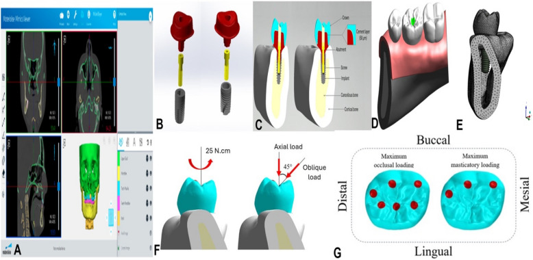 Figure 2
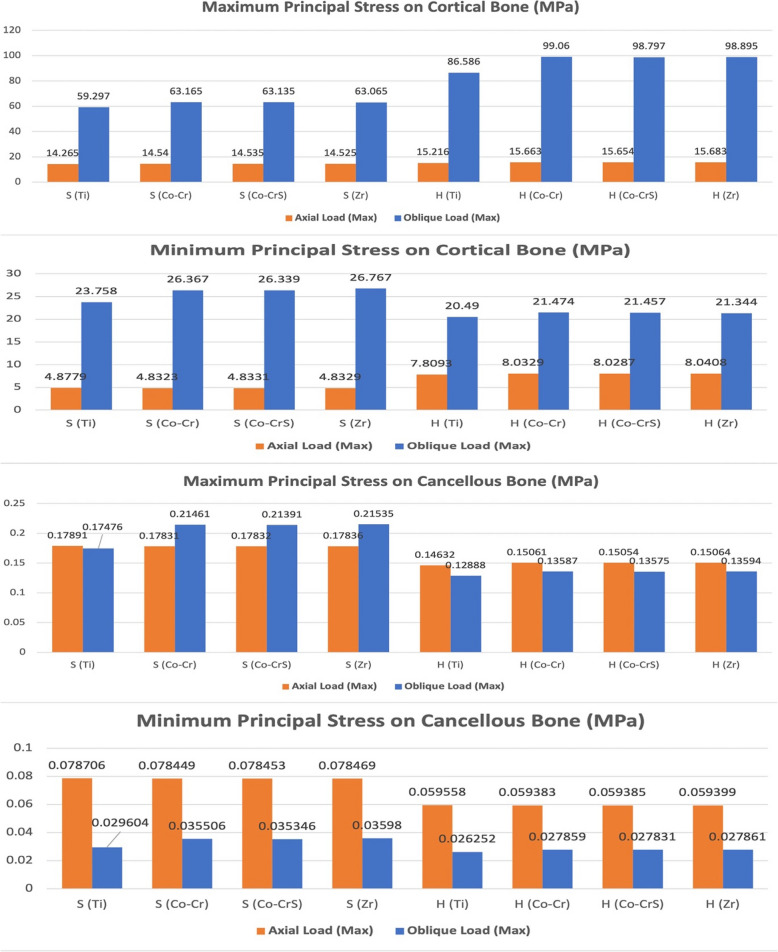 Figure 3
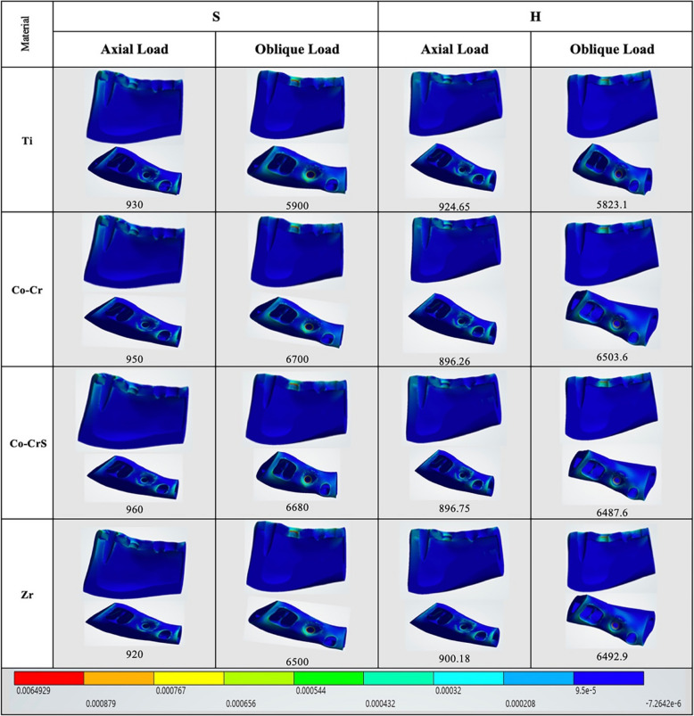 Figure 4
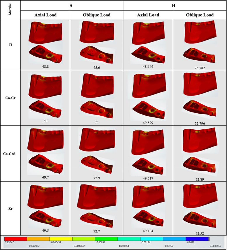 Figure 5
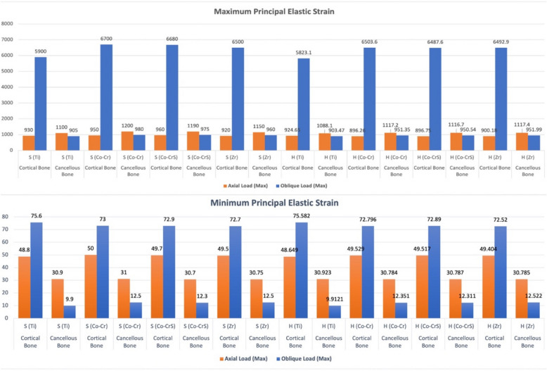 Figure 6
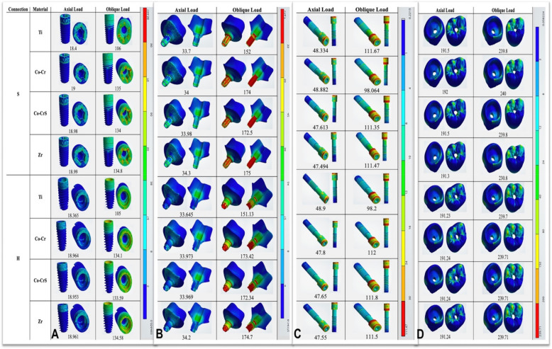 Figure 7
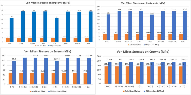 Figure 8
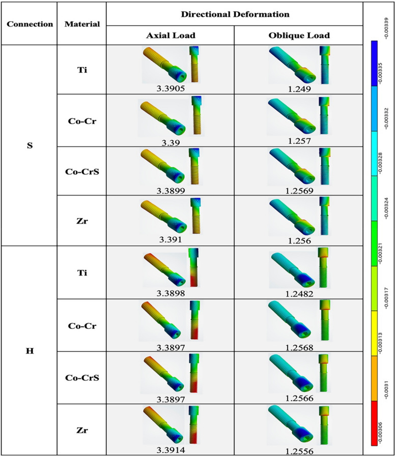 Figure 9
- —6 October University
Peer Reviews
No public reviews on file for this paper yet. If you reviewed it on a platform where reviews are public (OpenReview, ICLR, NeurIPS, ICML), you can paste yours below so the community can read it here.
Videos
No videos yet. Explain this paper in a talk, walkthrough, or lecture? Add one.
Taxonomy
TopicsDental Implant Techniques and Outcomes · Dental materials and restorations · Bone Tissue Engineering Materials
Background
The implant-abutment connection significantly influences the long-term clinical efficacy of dental implants [1]. These interfaces are typically categorized based on the geometric configuration of the coronal portion of the implant body [2]. Internal connections offer superior biological sealing and mechanical stability compared to external connections [3]. Numerous internal connection geometries have been developed, such as internal hexagonal, internal octagonal, conical, and tube-in-tube designs. These geometries yield a cold-welded interface with high friction levels [4, 5]. Under compressive loading, abutment settling reduces the microgap, allowing the two components to function as a single unit. This result limits microleakage while improving resistance to rotation and bending torque [6].
While readily available and clinically dependable, stock abutments exhibit restricted customization capabilities and may lead to inadequate emergence profiles and difficulties in cement removal, especially with subgingival margins [7, 8]. Customized abutments provide individualized emergence profiles and enhance adaptation to peri-implant mucosa, promoting esthetics and peri-implant tissue health [9]. Long-term randomized clinical trials have demonstrated that customized abutments yield comparably advantageous survival, biological stability, and aesthetic results, with follow-up durations reaching 13 years [10]. Furthermore, research comparing prefabricated abutments with those fabricated using computer-aided design and manufacturing (CAD/CAM) supports comparable survival rates and aesthetic results during short- and mid-term follow-up [11]. Nevertheless, other studies report no significant differences in plaque accumulation, probing depth, or aesthetic indices between customized and stock abutments after 1–3 years, indicating that material properties and connection design may have a more substantial biomechanical impact than customization alone [12].
Abutment material selection is critical in implant longevity, influencing mechanical stability, biological response, and clinical performance. Titanium has long been considered the gold standard due to its excellent mechanical strength, corrosion resistance, biocompatibility, and favorable osseointegration [13]. Despite these benefits, its metallic hue may detract from the anterior parts' aesthetics, and its higher elastic modulus than bone can occasionally help with stress shielding [14]. In contrast, cobalt-chromium (Co-Cr) abutments are more cost-effective and rigid than noble alloys, especially in light of the increased cost of gold. Although remarkable for their resistance to corrosion and wear, their grayish metallic color restricts their use in aesthetic applications, and biocompatibility concerns, such as tissue irritation and hypersensitivity, persist as challenges [15].
Soft-milled Cobalt-Chromium-Molybdenum (Co-Cr–Mo) alloys were developed to address these limitations. Integrating Co-Cr’s mechanical advantages with the precision of digital manufacturing results in superior surface finish, improved fit, and minimized marginal discrepancies, which may decrease the possibility of biological complications like peri-implantitis [16]. However, their long-term clinical performance is still inadequately studied compared to titanium and zirconia.
Zirconia abutments enhance esthetics in anterior regions due to their tooth-like color and translucency. Their biocompatibility is excellent, presenting a minimal risk of irritation or allergic reactions [17]. Nonetheless, their comparatively reduced fracture resistance when subjected to high occlusal forces limits their application in posterior areas or among patients exhibiting parafunctional habits [18].
Abutment material and connection design significantly impact how implant systems transfer mechanical loads among their constituent parts and the surrounding bone. Due to the increasing structural complexity brought about by advancements in implant-abutment connection design, it is now more challenging to measure occlusal load transfer and peri-implant stress distribution. Insufficient studies have been conducted regarding the relationship between connection design and abutment material in implant biomechanics. To overcome these difficulties, finite element analysis (FEA) has been used extensively to simulate mechanical performance under regulated loading circumstances.
This study examined two under-researched connection configurations: the star-shaped tube-in-tube, the hybrid Morse taper with internal hex, and four customized abutment materials. Unlike previous studies that mainly focused on connection type and abutment material in isolation, a multifactorial FEA was performed to evaluate the impact of these variables on stress distribution within the implant system and surrounding bone. To improve implant longevity and clinical results, this study aimed to provide biomechanical insights to help clinicians choose optimum connection designs and abutment materials. According to the study, implant biomechanics would significantly impact the interplay between abutment material and connection design. The first hypothesis was that the hybrid Morse taper with internal hex would demonstrate lower crestal bone stress and strain. The second hypothesis was that the hybrid Morse taper with internal hex would reduce stress within implant components, compared with the star-shaped tube-in-tube connection, particularly under oblique loading. The third research hypothesis is that abutment material would modulate stress distribution within implant components, with soft-milled Co-Cr–Mo exhibiting a more favorable pattern than titanium, Co-Cr, and zirconia.
Methods
The protocol for this study was approved by the Faculty of Dentistry, Beni-Suef University Research Ethics Committee (FDBSU-REC) (No. REC-FDBSU/0212025–04/ZA).
Implant system designing and modeling
Sixteen three-dimensional (3D) finite element models were established, consisting of an implant complex and alveolar bone in the mandibular first molar region (Fig. 1 and Table 1). A segment of the mandible, extending from the second premolar to the second molar, was chosen to reflect the clinical condition accurately and enhance computational efficiency for the simulation. Two parameters were considered: the implant-abutment connection design, which includes the Star-shaped tube-in-tube connection (S) (Torx®, Tube-in-Tube, Classic Sky, Bredent GmbH, Germany) and the Hybrid 5° Morse taper combined with an internal hex anti-rotation feature (H) (Conexa, Ev Line, B&B Dental S.r.l, Italy), as well as the abutment materials: Titanium Grade V (CORiTEC Titan Grade 5; pritidenta® GmbH, Leinfelden-Echterdingen, Germany), Co-Cr (Remanium Star MD II, Dentaurum, Germany), soft-milled Co-Cr–Mo (Ceramill Sintron, Ammann Girrbach, Austria), and Zirconia (Ceramill Zolid HT +, Ammann Girrbach, Austria). The exact diameter and length (4.1 mm × 10 mm) were used for each implant system. Both implants were digitally reconstructed using a reverse engineering technique to ensure precise replication of the implant geometry, thread design, platform connection, and screw. The abutments and crowns were designed using dental CAD software (exocad Dental CAD v3.0; exocad GmbH, Darmstadt, Germany) to ensure precise adaptation and optimal biomechanical performance. The thickness of the cement layer was set at 50 µm.Fig. 1 Finite element models of two tested implant systems: A Star-shaped tube-in-tube implant and B Hybrid 5° Morse taper combined with internal hex anti-rotation feature implant, showing the internal configuration and integrated assemblyTable 1 Finite element modelsModelConnection typeAbutment materialLoading typeS1Star-shaped tube-in-tube (S)Titanium (Ti)AxialS2Star-shaped tube-in-tube (S)Co-Cr (Co-Cr)AxialS3Star-shaped tube-in-tube (S)Soft-milled Co-Cr–Mo (Co-CrS)AxialS4Star-shaped tube-in-tube (S)Zirconia (Zr)AxialS5Star-shaped tube-in-tube (S)Titanium (Ti)ObliqueS6Star-shaped tube-in-tube (S)Co-Cr (Co-Cr)ObliqueS7Star-shaped tube-in-tube (S)Soft-milled Co-Cr–Mo (Co-CrS)ObliqueS8Star-shaped tube-in-tube (S)Zirconia (Zr)ObliqueH9Hybrid Morse taper with internal hex (H)Titanium (Ti)AxialH10Hybrid Morse taper with internal hex (H)Co-Cr (Co-Cr)AxialH11Hybrid Morse taper with internal hex (H)Soft-milled Co-Cr–Mo (Co-CrS)AxialH12Hybrid Morse taper with internal hex (H)Zirconia (Zr)AxialH13Hybrid Morse taper with internal hex (H)Titanium (Ti)ObliqueH14Hybrid Morse taper with internal hex (H)Co-Cr (Co-Cr)ObliqueH15Hybrid Morse taper with internal hex (H)Soft-milled Co-Cr–Mo (Co-CrS)ObliqueH16Hybrid Morse taper with internal hex (H)Zirconia (Zr)Oblique
Mandibular bone block model
The mandibular bone block model was reconstructed based on the cross-sectional images of the right first molar region obtained from cone beam computed tomography (CBCT) images (Mimics 21.0; Materialise, Leuven, Belgium) (Fig. 2A). The bone tissue comprised cancellous bone in the center, surrounded by 2 mm of cortical bone. The segmented 3D model (Fig. 2B) was exported in Standard Tessellation Language (STL) format and further refined (Geomagic Design X 2024.3.1; 3D Systems, SC, USA) to ensure smooth surfaces and correct any geometric errors before final processing. The segmented bone, implant, abutment, and crown components were assembled in a 3D model (SolidWorks 3D CAD; SolidWorks Dassault Systèmes Corp., MA, USA) (Fig. 2C and D) to ensure precise anatomical representation. The Boolean operation functions facilitated the integration of the mandibular bone block model with the dental implant model (Magics 20.03; Materialise, Leuven, Belgium).Fig. 2 Finite element model construction: A 3D mandible creation and segmentation with thresholding from CBCT data; B Unassembled models; C Assembled models. D 3D assembly; E 3D CAD model meshing; F Loading orientations; and G Loading locations
Material properties of assembly models
The material properties of the model components were defined according to data from the literature and summarized in Table 2 ([19–24], https://www.dentaurum.de/files/989-300-23.pdf, https://store.amanngirrbach.com/produkt/cad-cam-materialien/metall/ceramill-sintron/ceramill-sintron-98x12-f/?no_redirect=1, [25]). All materials were assumed to be homogeneous, linearly elastic, and isotropic.Table 2 Material properties of the finite element modelsMaterialModulus of elasticity (MPa)Poisson's ratioReferenceZirconia crown200000.31[19]Cement77000.24[20]Cortical bone137000.30[21]Cancellous bone13700.30[21]Gingiva3.00.45[22]Titanium abutment (Grade V)1140000.33[23]Zirconia abutment2063000.25[24]Co-Cr abutment2020000.31(https://www.dentaurum.de/files/989-300-23.pdf)Soft-milled Co-Cr abutment2000000.31(https://store.amanngirrbach.com/produkt/cad-cam-materialien/metall/ceramill-sintron/ceramill-sintron-98x12-f/?no_redirect=1)Titanium implant (Grade IV)1070000.33[25]Titanium abutment screw (Grade IV)1070000.33[25]
Interface conditions
A "frictional" contact condition was applied at the bone-implant connection to replicate the integration between the implant and the peri-implant bone in immediate placement scenarios. The interface between the prosthesis and the gingiva was modeled as bonded to facilitate realistic transmission of masticatory forces. Surface contacts were defined at the implant-abutment, abutment-screw, and abutment-cement interfaces, with frictional behavior determined by the quality of surface finishing. The assigned friction coefficients for these interfaces were 0.16, 0.441, and 0.25, respectively [26]. All other contact surfaces in the model were considered fully bonded [27].
Meshing
The assembled models were imported into engineering simulation software (ANSYS Mechanical APDL Element Referenc; Release 18.2; ANSYS, PA, USA) to generate 10-node tetrahedral elements (Solid187) for the following simulation and calculations. A refined parabolic tetrahedral mesh with an element size of approximately 0.2 mm was applied in the regions surrounding the implant and peri-implant bone. In contrast, a coarser mesh was implemented for the adjacent soft tissues to maintain geometric accuracy and computational efficiency (Fig. 2E). Each model's total node and element numbers were recorded to ensure consistent analysis conditions (Table 3). Mesh convergence was evaluated through iterative refinement until the relative variation in maximum von Mises stress fell below 1%, signifying sufficient mesh resolution. It ensured both numerical stability and model reliability [28, 29].Table 3 The total number of elements and nodes for each implant systemModelNodesElementsStar shaped tube-in-tube implant system (S)415002264239Hybrid Morse taper with internal hex anti-rotation feature implant system (H)412692262563
Loads and boundary constraints
All models were subjected to uniform loading and boundary conditions (Fig. 2F and G). The mesial, distal, cortical, and cancellous bone surfaces were constrained in the x, y, and z directions to eliminate displacement.
The simulation proceeded in two sequential steps (Fig. 2F). First, a preload corresponding to a screw tightening torque of 25 N.cm was applied, calculated using Bickford's formula, to simulate initial fixation. Next, functional masticatory forces were applied to the crown. A load of 200 N was distributed axially over 60 nodes encompassing three cusps and three fossae. To mimic non-axial loading, a 100 N force was used at a 45° buccolingual angle across 30 nodes on three buccal cusps (Fig. 2G). During load application, a reference point was established at the center of the abutment plane, with coupling constraints defined between this point and the coupling nodes on the abutment plane, ensuring that forces applied at the reference point were equivalently transmitted to the coupling nodes.
Finite Element Analysis (FEA)
FEA was conducted (ANSYS Mechanical APDL Element Reference; Release 18.2; ANSYS, PA, USA). The maximum and minimum principal stresses and strains in the peri-implant bone were assessed. Positive values represented tensile stresses, whereas negative values denoted compressive stresses. The peaks of von Mises stress were examined to evaluate the biomechanical reactions of the implant components, including the implant body, abutment, implant-abutment connection, screw, and crown. Deformation analysis was performed along the Z-axis to simulate screw loosening, evaluating displacement under various loading conditions across all models.
Results
Bone stress and strain distribution
Maximum and minimum principal stresses were predominantly concentrated in the cortical crestal bone (Fig. 3). Under axial loading, both implant-abutment connections exhibited similar cortical bone stress magnitudes, with peak values ranging from 14.265 MPa S (Ti) to 15.683 MPa H (Zr). Oblique loading caused a significant increase in cortical bone stress, especially in the hybrid Morse taper with internal hex models, which reached peak compressive stresses up to 99.06 MPa in H (Co-Cr) compared to 59.297 MPa in S (Ti).Fig. 3 Chart illustrating the variation in maximum and minimum principal stress (MPa) recorded on the peri-implant bone (cortical and cancellous) of the 16 models under axial and oblique loadings
Cancellous bone stresses were considerably lower than cortical bone stresses across all models and loading conditions (Fig. 3). In axial loading, stresses ranged from 0.14632 MPa for H (Ti) to 0.17891 MPa for S (Ti). Meanwhile, oblique loading stresses ranged from 0.12888 MPa for H (Ti) to 0.21535 MPa for S (Zr).
Axial loading produced the highest elastic strain values in cortical bone in the S (Co-CrS) model (960.0 με). In comparison, the H (Co-Cr) and H (Co-CrS) models exhibited the lowest elastic strain values (896.26 and 896.75 με, respectively). Oblique loading significantly increased strain, peaking at 6700.0 με in the S (Co-CrS) model (Figs. 4, 5 and 6).Fig. 4 The distribution of the maximum principal strains on the cortical bone in the models with different connection designs and abutment materials for two loading conditionsFig. 5 The distribution of the minimum principal strains on the cortical bone in the models with different connection designs and abutment materials for two loading conditionsFig. 6 Chart illustrating the variation in maximum and minimum elastic strain (με) recorded on the peri-implant bone (cortical and cancellous) of the 16 models under axial and oblique loadings
In cancellous bone (Fig. 6), strain values were generally lower and exhibited less variability, with the maximum axial strain (1200.0 με) recorded in the S (Co-Cr) model. Conversely, the H (Ti) exhibited the lowest values at 1088.1 με. Under oblique loading, all models showed lower elastic strain values. The highest strain (980.0 με) was observed in the S (Co-Cr), while H (Ti) had the lowest value (903.47 με).
The maximum and minimum stresses of cortical and cancellous bone and the strain distribution in cancellous bone are presented in supplementary figures (S1-S6) to complement the main text results.
Implant, abutment, and crown stress
Von Mises stresses were concentrated primarily in the implant neck region across all models (Fig. 7A). Under axial loading, implants demonstrated low stress values, ranging from a minimum of 18.365 MPa in H(Ti) to a maximum of 19.0 MPa in S (Co-Cr). Oblique loading significantly elevated implant stresses, especially in the S (Co-Cr) model, reaching 135.0 MPa. In comparison, titanium abutments in both connections consistently showed lower stress concentrations (106.0 for S and 105.0 MPa for H models) (Figs. 7A and 8).Fig. 7 The distribution of the von Mises stress in the implants (A), abutments (B), screws (C), and crowns (D) in the models with different connection designs and abutment materials for two loading conditionsFig. 8 Chart illustrating the variation in von Mises stress (MPa) recorded on the implants, abutments, screws, and crowns of the 16 models under axial and oblique loading appliances
In both connection types, the highest stresses were located at the abutment neck under axial and oblique loading (Fig. 7B). Stress values were nearly the same for the S and H abutments. Under axial loading, the lowest stress was in the S (Ti) model (33.7 MPa) and the highest in the H (Zr) model (34.2 MPa). Oblique loading caused a marked stress increase, reaching 175.0 MPa in the S (Zr) model. Titanium abutments showed lower stresses under oblique loading, with 152.0 MPa S (Ti) and 151.13 MPa H (Ti) (Fig. 8).
Screw stresses were mainly concentrated in the screw heads and internal threads in both models (Fig. 7C). Under axial loading, stress values were comparable, with the minimum recorded in the H (Zr) model at 47.494 MPa. Oblique loading significantly elevated stresses, attaining 111.8 MPa in the S (Co-Cr) model. Titanium screws showed lower stresses under oblique loading, with 98.2 MPa for S(Ti) and 98.064 MPa for H (Ti) (Figs. 7C and 8).
Both connection types showed comparable stress values for crowns under axial and oblique loading (Figs. 7D and 8). The maximum stress under axial loading was 192.0 MPa in the S (Co-Cr) model. Oblique loading produced higher but similar stresses across all models (~ 240 MPa).
Supplementary figures (S7-S10) present the von Mises stresses of the implant, abutment, and crown, as well as the deformation patterns of the screw, for a comprehensive evaluation.
Screw deformation
Directional screw deformation showed minimal variation across models under axial loading, with the lowest value in H (Co-Cr) and H (Co-CrS) (3.897 µm). Deformation values under oblique loading were consistently lower across all models, with the maximum observed in S (Co-CrS) at 1.257 µm. Stress concentrations were identified at the screw head, base, and thread root, with amplification occurring due to eccentric loading (Fig. 9). No significant differences in screw deformation were observed between models under both loading conditions, indicating comparable mechanical behavior (Figs. 9 and 10).Fig. 9 Directional deformation (µm) on the screws in the models with different connection designs and abutment materials for two loading conditionsFig. 10 Chart illustrating the variation in directional deformation (µm) recorded on the screw of the 16 models under axial and oblique loadings
Discussion
The FEA provides an understanding of the fundamental mechanics of a specific technical system. It can indicate the internal stress and system vulnerabilities [30]. Dental implant researchers use FEA to assess the stress distribution in critical components and biomechanical performance under various loading circumstances [31, 32]. In the present study, commercial implants were modeled to mimic actual ones. Consequently, this analysis facilitates a more rational selection of a suitable implant connection type and abutment material. However, prior FEA studies often suffer from limitations in model design and validation [33, 34].
In this study, two internal connection designs with differing engineering principles were compared: a star-shaped tube-in-tube design featuring a Torx-like anti-rotational component and cylindrical mating surface, promoting centralized force transmission and consistent seating; and a hybrid design combining a conical interface with an internal hex, valued for its alignment ease and rotational resistance [35, 36]. These systems reflect real-world clinical choices and allow a meaningful analysis of how connection geometry influences the implant biomechanics when paired with different abutment materials.
This study was structured to replicate an optimally managed clinical prosthesis scenario. As the reported average maximum occlusal force in the molar region is 545.7 N, with the maximal masticatory force estimated to be approximately 37–40% [37, 38], the present investigation duplicated maximum occlusal and masticatory forces by delivering a load of 200 N (about 37%). Furthermore, Misch documented standard maximum occlusal forces in the posterior region, varying from 200 to 300 N per implant during regular function [39]. The implant and surrounding bone experience increased stress when force is applied at a singular point [40]. As a result, this investigation employed external stresses at six locations in two distinct orientations: 60 nodes positioned on three buccal cusps and three fossae identified by the precise occlusal position during functional movements to allocate the external loads correctly [41]. While both axial and oblique loads are applied in clinical conditions, oblique loading should be prioritized in analyses, as it represents a realistic occlusal condition and induces significantly higher stress concentrations in cortical bone and implant components than axial loading [42, 43].
The greatest stress concentration transferred to the adjacent bone was noted in the cortical bone. The superior resistance of cortical bone relative to cancellous bone is due to its modulus of elasticity, which is 7–10 times higher, resulting in greater stress concentrations in this area [44]. Gross and Zanatta et al. confirmed that the cortical bone region closest to the cervical area of the implants is the most impacted by occlusal loads, irrespective of bicorticalization [45, 46]. In contrast, softer cancellous bone deforms less under oblique load. As oblique forces do not align with the principal structural axes of cancellous bone (vertical trabeculae), stress is redirected and concentrates in the cortical regions. [47].
The first research hypothesis was partially rejected. The S connection exhibited the lowest axial stress compared to the H connection, with both remaining within the maximum feasible cortical bone stress of 100 MPa [48]. The findings of this study align with previous results, demonstrating that the evaluated implants and connections possess significant capacity for dissipating masticatory loads and exhibit minimal stress concentration in the cortical regions, which could potentially lead to resorption in the marginal bone in the crest area [49, 50]. This might be due to the stable implant-abutment connection permitting stress distribution along the long axis of the implant, thus reducing stress in the cortical bone [32, 51]. Moreover, the cancellous bone of the S implant system exhibited greater maximum stress (average 0.21 MPa) compared to the H implant system (average 0.15 MPa). The H connection might explain this, as it distributes axial forces more evenly and gradually through the conical interface that offers an intimate fit**.**
In contrast, S connection might tend to localize stress at the star corners and threads, transferring higher peak stresses to the cancellous cone, which could not distribute them as efficiently. Markedly decreased stresses were recorded for H models under oblique loading. This decrease could be explained by the H model's conical design, which enhances self-locking and friction under oblique loading, increasing radial engagement and converting lateral forces into axial compression. The result improved implant-abutment stability, reduced micromovement, and led to lower peak stresses compared to axial loading. Nonetheless, both connection types exhibited stresses below the maximal stress threshold (5.0 MPa) for the onset of cancellous bone resorption [52].
During axial loading, both S and H implant-abutment connections produced strain levels within physiological safety limits: 50–1500 με for cancellous bone and 200–2500 με for cortical bone [53, 54]. In contrast, oblique loading resulted in strain values that exceeded safe thresholds for connection types and all abutment materials. Cortical bone showed high strain levels above 6000 με that would induce bone remodeling as mechanical strain reached a threshold sufficient to stimulate cellular response, reflecting stress transmission through bone tissue [54, 55]. In contrast, cancellous bone exhibited reduced strains under identical conditions. The observed discrepancy can be attributed to the increased stiffness of the cortical bone, resulting in greater absorption of oblique forces.
The present investigation revealed that both connections exhibited nearly similar stresses on the implant, abutment, crown, and screw that did not exceed the yield strength of titanium alloy (780–950 MPa) [56]. Therefore, the second hypothesis was rejected. The star-shaped tube-in-tube implant-abutment connection represents a biomechanical innovation to enhance rotational stability and optimize stress distribution throughout the implant assembly (https://www.bredent-implants.com/wp-content/uploads/2023/12/Prospekt-SKY-Implantatsystem_009991GB_20231206_low-.pdf). The multi-lobed internal design enhances the contact surface area between the implant and abutment, optimizes load distribution across several lobes rather than just the screw shank, redirects load paths from the screw threads to the implant body, and reduces micromovement under occlusal loads. A star design may facilitate a more concentrated axial load transmission, reducing interface shear stresses. This led to less compressive and tensile stress in the peri-implant bone along the cortical boundary, relative to H groups, facilitating crestal bone preservation and possibly mitigating the risk of marginal bone loss. This is based on a previous study that reported that the tube-in-tube connection type exhibited lower stress values in most loading and tilting simulations in the implant components and the peripheral bone [57].
The hybrid Morse taper with internal hex implant-abutment connection tends to transfer more load to the surrounding cortical bone than the star-shaped tube-in-tube connection, possibly due to the lower compressive strength of the internal hex within a Morse taper configuration. Studies have shown that Morse taper systems incorporating an internal hexagon can exhibit significant interface distortion [58]. However, some findings indicated that a conical connection with an internal hex results in minimal stress on both the implant and surrounding bone [59]. The Morse taper system operates via surface friction, known as cold welding, where microscopic surface roughness induces pressure that causes fusion of the surfaces, creating a near-integral connection. This promotes uniform stress distribution across the implant-abutment connection [30]. The findings align with the study by Lin et al. and Hansson et al., who observed that conical implant-abutment connection systems exhibited superior performance as a force transmission system compared to internal hexagonal and external flat-top systems [60, 61]. However, other studies indicated increased von Mises stresses in the neck region of the abutment-prosthesis complex, alongside a notable abutment fracture rate of 2.2%, with all fractures localized to the abutment neck and screw [62, 63].
The deformation of the prosthetic abutment screw may lead to mechanical instability and elevate the risk of screw loosening over time. The current study found that both connection groups displayed comparable directional deformation patterns when subjected to axial and oblique loading conditions. The overall magnitude of deformation was minimal, likely attributable to the implant's inherent rigidity, abutment, crown materials, and precise fit of the implant components. The aforementioned factors collectively improve the mechanical stability of the prosthetic assembly. This finding aligns with earlier research indicating that screw loosening is less prevalent in Morse taper with internal hex connections than in octagon designs, due to the decreased separation between the screw and the internal abutment surface when subjected to load [64]. Therefore, it was observed that less stress was transferred to the screw. However, it was reported that masticatory forces up to 550 N were well within the abutment screw's capacity to sustain extended service life and maintain its elastic behavior [65]. However, abutment screw deformation is influenced by several factors, including screw geometry, design variables, material properties, applied torque, loading condition, implant diameter, and the presence of a micro gap that may potentially lead to screw loosening or fracture [33, 66].
The third hypothesis was rejected. The Ti abutment exhibited the most favorable performance in both connection groups under oblique loading. Titanium is distinguished by remarkable ductility, enabling titanium abutments to absorb and redistribute loads, thus mitigating catastrophic failure. Titanium might bend or deform under excessive stress instead of fracturing. The elastic modulus of titanium (110 GPa) is more akin to that of bone (13–20 GPa) [67]. This higher stiffness alignment enhances stress distribution, consequently diminishing stress accumulation at the bone-implant interface, which reduces the risk of bone resorption and demonstrates greater stress dispersion and fatigue resistance [14]. Biomechanical advantages are substantiated by randomized controlled trials and prospective studies demonstrating high survival rates and soft tissue stability associated with titanium CAD/CAM abutments [68, 69].
However, Co-Cr and soft milled models demonstrated moderate stress values that exceeded Ti's. A multicenter retrospective study of Co-Cr single crowns indicated a cumulative survival rate of approximately 90.3% at 5 years, with minimal material-related complications [70]. Comprehensive data on ceramic-veneered Co-Cr fixed prostheses demonstrate a 5-year survival rate of 92.8%, highlighting their clinical effectiveness [71]. The clinical observations correspond with contemporary biomechanical findings demonstrating advantageous soft-milled Co-Cr–Mo stress distribution patterns. Co-Cr demonstrates a higher elastic modulus and greater strength than titanium, albeit with reduced ductility. This characteristic may enhance stress transfer to the adjacent bone, potentially increasing the risk of stress shielding and remodeling [72]. Additionally, the reduced biocompatibility of Co-Cr alloys relative to titanium and zirconia raises concerns, particularly in individuals with metal hypersensitivity, since it may elicit allergic reactions or peri-implant inflammation [16].
Zirconia abutments demonstrate stress levels similar to those of Co-Cr abutments, affirming their safety and aesthetic benefits. A 13-year randomized controlled trial comparing zirconia and titanium abutments demonstrated 100% survival rates for both implants and restorations, with no significant differences observed in biological or esthetic outcomes [73]. Systematic reviews indicate a high implant survival rate of approximately 96%, accompanied by marginal bone loss and probing depths comparable to, or in some instances slightly superior to, those associated with titanium [74]. While zirconia may provide superior esthetic outcomes in patients with thin gingival biotypes, differences in survival and biological performance are minimal [75, 76]. However, zirconia’s ability to undergo plastic deformation is limited; it can fracture suddenly and unpredictably if its tensile strength is exceeded. FEA frequently reveals elevated tensile stresses in critical areas, specifically at the cervical margin of the abutment under oblique loading and at the abutment-implant connection [77]. However, zirconia demonstrates a significantly greater elastic modulus than bone, with values of 200 GPa for zirconia and 13 GPa for cortical bone. This disparity may result in stress shielding, where the diminished load is transferred to the bone, potentially leading to bone resorption and localized stress transfer, which increases the risk of mechanical overload [78, 79].
Although stress distribution varies depending on abutment material, clinical outcomes indicate that titanium, Co-Cr, and zirconia abutments can all be successfully used, with the choice guided by functional demands, esthetic goals, and cost considerations.
Limitations
Although this investigation is founded upon an FEA that simulates mechanical behavior, it relies on idealized assumptions. The model did not account for the dynamics of soft tissue, the process of bone remodeling, or the individual occlusal forces. ial properties were assumed to be linearly elastic, homogeneous, and isotropic, which may not accurately represent in vivo conditions. Furthermore, this study neglects to address long-term fatigue behavior and does not account for possible manufacturing flaws in customized abutments. The loading conditions were static and applied at specific locations, whereas real-world masticatory loads are more dynamic and multi-directional.
Additionally, stress distribution is influenced by parameters that extend beyond the geometry of the implant and abutment, such as the number of components (one- versus two-piece), screw dimensions, thread design, material, and contact area, which were not considered in the current study [80]. FEA data alone is insufficient for predicting clinical outcomes, such as aesthetics, long-term survival, and soft tissue health. Future research should integrate clinical follow-ups and fatigue testing to validate these biomechanical findings.
Conclusions
The star-shaped tube-in-tube and hybrid Morse taper with internal hex connections exhibited comparable stress distribution across implant components, with stresses remaining below the yield strength of titanium alloy, signifying a minimal risk of mechanical failure. Both connections induced safe stress levels in the surrounding bone but caused cortical bone strains exceeding the safe limit under oblique loading. Zirconia, Co-Cr, and soft-milled Co-Cr abutments exhibited moderate, evenly distributed stresses, while titanium abutments provided the most favorable stress distribution. Both connection types also showed minimal screw deformation, suggesting reduced risk of screw loosening.
Supplementary Information
Supplementary Material 1.
The reference list from the paper itself. Each links out to its DOI / PubMed record.
- 1Sütpideler M, Eckert SE, Zobitz M, An KN. Finite element analysis of effect of prosthesis height, angle of force application, and implant offset on supporting bone. Inter J Oral Maxillofac Implants. 2004;19. https://openurl.ebsco.com/EPDB%3Agcd%3A 6%3A 13355494/detailv 2?sid=ebsco%3Aplink%3Ascholar&id=ebsco%3Agcd%3A 36846358&crl=c&link_origin=none 15623056 · pubmed ↗
- 2Natali AN, Pavan PG. Numerical approach to dental biomechanics AN NATALI, PG PAVAN. J Dent Biomech. 2003:229–57. https://www.taylorfrancis.com/chapters/edit/10.1201/9780203514849-14/numerical-approach-dental-biomechanics-natali-pg-pavan-natali-pg-pavan