Anaerobic Pyrolysis Chamber: An atmosphere-controlled furnace for controlled-atmosphere thermal decomposition
Ryan T. Chaffer, Joseph Johnson, Matthew J. DiDomizio, Mark B. McKinnon

TL;DR
A new furnace called the Anaerobic Pyrolysis Chamber allows controlled thermal decomposition of materials without combustion, enabling detailed study of partially decomposed samples.
Contribution
The novel Anaerobic Pyrolysis Chamber enables controlled pyrolysis in an inert atmosphere, allowing for the isolation of partially decomposed material samples.
Findings
The APC successfully produces gram-scale samples of partially decomposed materials.
The APC maintains precise control over temperature, pressure, and oxygen concentration during pyrolysis.
The APC supports property measurement in subsequent research studies.
Abstract
As some materials are heated they undergo thermal decomposition, resulting in a change in the material’s physical structure and chemical composition through a process called pyrolysis. During pyrolysis, flammable vapors are driven off the material; if those vapors are released in the presence of oxygen, flaming combustion may occur. Combustion can accelerate the decomposition process, making it difficult to isolate and harvest partially decomposed material samples for subsequent analysis. Due to this difficulty, the thermo-physical changes to materials undergoing pyrolysis have not been extensively studied. A new apparatus, termed the Anaerobic Pyrolysis Chamber (APC), was designed to produce gram-scale samples of partially decomposed materials by pyrolyzing those materials under a defined heating protocol and in an inert atmosphere. The APC consists of a decomposition chamber…
Genes, proteins, chemicals, diseases, species, mutations and cell lines named across the full text — each resolved to its canonical identifier and authoritative record.
Click any figure to enlarge with its caption.
 Figure 1
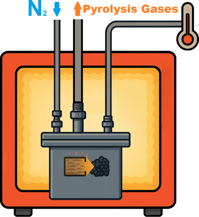 Figure 2
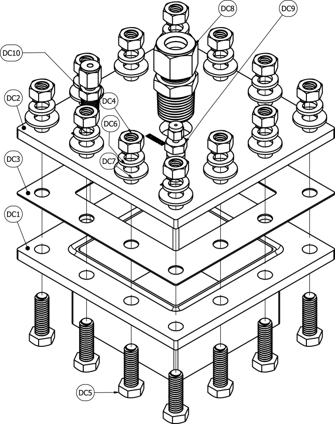 Figure 3
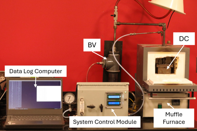 Figure 4
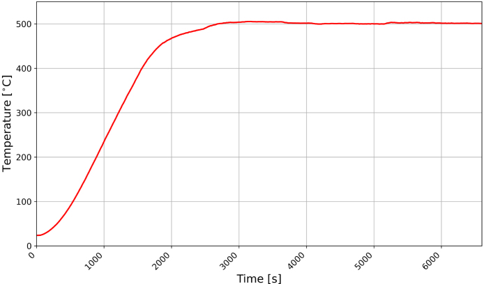 Figure 5
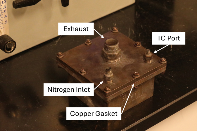 Figure 6
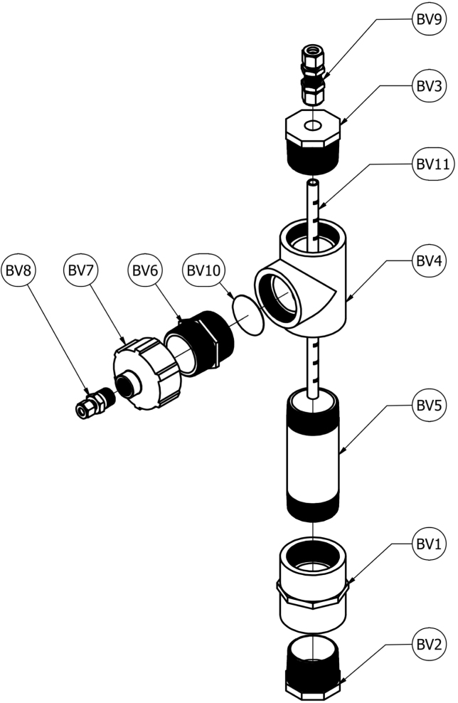 Figure 7
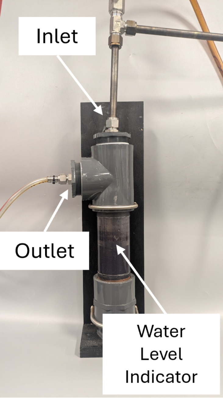 Figure 8
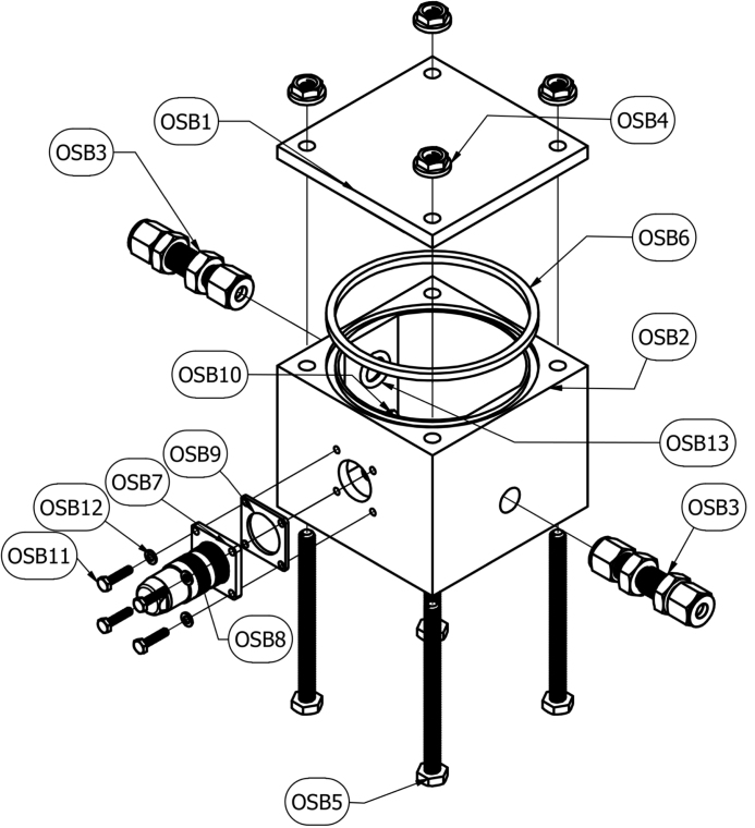 Figure 9
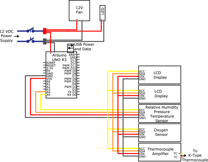 Figure 10
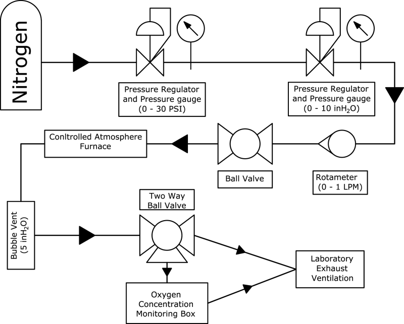 Figure 11
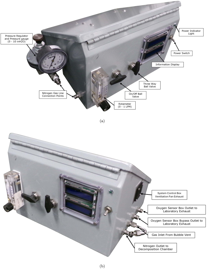 Figure 12
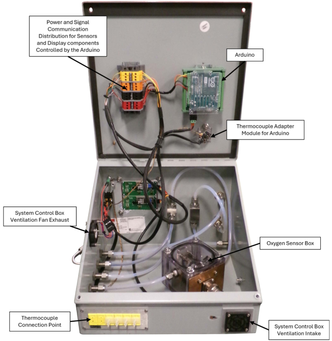 Figure 13
Peer Reviews
No public reviews on file for this paper yet. If you reviewed it on a platform where reviews are public (OpenReview, ICLR, NeurIPS, ICML), you can paste yours below so the community can read it here.
Videos
No videos yet. Explain this paper in a talk, walkthrough, or lecture? Add one.
Taxonomy
TopicsThermochemical Biomass Conversion Processes
Specifications table
Table 1. Specifications table.Hardware nameAnaerobic Pyrolysis ChamberSubject areaEngineering and material scienceHardware typeExperimental solid material preparationClosest commercial analogThe closest commercial analog are a class of products called inert atmosphere furnaces.Open source licenseCreative Commons Attribution Share Alike 4.0 International licenseCost of hardware$5,996.00Source file repositoryhttps://doi.org/10.5281/zenodo.10215409
Hardware in context
1
As materials become involved in fires they undergo thermal decomposition in a process called pyrolysis. As a material pyrolyzes the physical structure and chemical composition of the materials change as flammable volatiles are driven off the solid material and participate in combustion reactions to produce a flame. The physical and chemical changes to the solid materials result in changes to the thermo-physical (thermal conductivity, specific heat capacity, density) and optical (emissivity, absorption coefficient) properties [1]. An understanding of the properties of a material involved in a fire is critical to a complete understanding of the fuel generation rate of materials and the fire dynamics of a burning scenario [2].
When a material undergoes flaming combustion, fuel vapors mix with air to form a diffusion flame that is seated on the surface of the material. One side of the flame sheet is characterized by a concentration gradient of volatile flammable gases that decreases from the material surface to the flame sheet; the concentration of the gas mixture within this region is above the upper flammability limit. The opposite side of the flame sheet is characterized by ambient air and gaseous products of combustion. At the interface of these two regions is a flame sheet. Because oxygen is completely consumed in combustion reactions at the flame sheet, no oxygen diffuses through the flame and the region on the fuel-rich side of the flame may be modeled as inert.
The systems that are typically utilized to effectively simulate a burning material sustaining a diffusion flame when thermal decomposition processes are studied or measurement of the gaseous or solid products of decomposition is required involve controlled heating in a well-characterized inert atmosphere. At present there are few commercially-available products that are specifically designed for generating an inert atmosphere in a controlled high temperature environment. The commercially-available systems that are capable of generating conditions consistent with these requirements include thermal analysis instruments and inert atmosphere furnaces.
Thermal analysis techniques, including thermogravimetric analysis, differential scanning calorimetry, microscale combustion calorimetry, etc., typically utilize well-controlled heating regimes and afford the ability to adjust the gas atmosphere based on the desired measurement. These techniques and the apparatus designed to conduct such experiments are typically limited to sample masses on the order of a few milligrams, so they may only be used to investigate thermal decomposition when transport processes are not rate-limiting. Because of these limitations, the solid products of decomposition are not representative of those produced when real-scale materials are involved in fires. Additionally, the smaller scale of the material results in smaller residence times within the material matrix for the gaseous effluent which may affect the composition of gas mixture.
Commercially-available inert atmosphere furnaces are primarily used for heat treating in manufacturing processes that require inert atmosphere protection (i.e., shielding from oxidation). These furnaces are designed with various form factors and temperature ranges to provide flexibility for a wide range of applications, but, critically, these products are not designed to accommodate materials that decompose to produce flammable gases. A gas mixture that is at a high temperature and a concentration above the upper flammability limit poses a detonation or deflagration hazard if any oxygen is introduced to the mixture. Safeguards are necessary to ensure safety when decomposing materials that release flammable vapors, and this is not a primary design consideration in inert atmosphere furnaces which are not designed for such a use case.
The Anaerobic Pyrolysis Chamber (APC) was designed to be a low-cost and configurable apparatus to safely pyrolyze materials in a temperature and atmosphere controlled environment. It was designed to be compatible with any commercial muffle furnace having a suitable port opening.
Hardware description
2
The APC is comprised of four major components: the decomposition chamber, bubble vent, oxygen sensor module, and control module.
The decomposition chamber (DC) is used to house samples during the heating process. The DC maintains a sealed environment, free of oxygen, via continuous nitrogen injection for the duration of the heating process. The DC is positioned inside a muffle furnace, wherein samples may undergo pyrolysis during the heating process. The small form factor of the DC (5 in. by 5 in. by 2-9/32 in.) aids in its versatility to be used in a wide range of furnace sizes. The two-piece design (consisting of a base and lid that are bolted together, as opposed to a hinged design), ensures a tight seal that can withstand high pressures in the case of oxygen intrusion and a subsequent deflagration.
The DC key features are the inert gas port, thermocouple port, exhaust port, and copper sealing gasket. The 1/8 in. inert gas inlet port is used to supply nitrogen to the DC and create an anerobic environment for material decomposition to occur. A 1/16 in. ungrounded K-type Inconel thermocouple is mounted in the thermocouple port to monitor temperatures inside the DC. The DC chamber thermocouple is also used as the thermocouple sensor input for the furnace temperature controller. By incorporating a thermocouple to collect temperature internal of the DC, users are able to ensure the decomposed samples are at the minimum required temperature to produce stable, solid products of decomposition. A 1/2 in. exhaust port is used to evacuate gaseous products of decomposition and route exhaust gases to the oxygen sensor module to determine oxygen concentration inside the chamber. A copper sealing gasket is placed between the chamber base and chamber lid. With eight through-bolt fastening locations, the copper gaskets malleability allows deformation and creates a tighter seal with the stainless-steel base and lid.
The bubble vent (BV), depicted in Fig. 3, is a pressure control device used to force positive pressure in the DC, cool hot exhaust gases, and filter out cooled products of decomposition. Positive pressure is ensured by restricting the exhaust gas flow, maintaining exhaust back pressure at a minimum of 5 inH_2_O (0.18 psig). Constructed from off-the-shelf components including PVC pipe, polypropylene tubing, stainless steel fittings, and mesh filters, the BV is a simplistic, easy to manufacture, and effective device to promote positive pressure. The main reservoir of the BV is constructed of 2 in. clear PVC pipe. Exhaust gases from the DC are transported to the BV inlet via 1/2 in. stainless steel tubing. A 30 30 stainless steel mesh filter is included in the BV exhaust outlet to aid in removal of cooled gas condensate before the gases are transported to the oxygen sensor module. With repeated sample decompositions, the BV will require periodic maintenance of replacing the water and cleaning of the stainless steel mesh filter. The maintenance schedule will be dependent on the quantity and material type being pyrolyzed.Fig. 3. Schematic of Bubble Vent.
The oxygen sensor module (OSB), depicted in Fig. 5, is a sealed chamber equipped with an electrochemical oxygen sensor and an environmental sensor to measure the temperature, relative humidity, and pressure within the instrument. The purpose of the OS is to measure the oxygen concentration of the exhaust stream after it exits the DC and travels through the BV. 3D printed from Accura ClearVue filament and seal by an o-ring, the two-piece design allows operators to replace the electrochemical oxygen sensor when it reaches the end of its usable life. Additionally, operators can quickly identify condensate build up, if any, within the oxygen sensor module. Utilizing sealed electrical connections, power is delivered and data signals are transferred to and from the Arduino while maintaining an airtight seal. The OSB is the primary component used to ensure no leakage is present during the decomposition process, certifying an anaerobic environment within the DC.Fig. 5. Schematic of Oxygen Sensor Module.
The system control module (SC), seen in Fig. 8, Fig. 9, is used to control and monitor all electrical and gas flow components of the Anerobic Pyrolysis Chamber. Nitrogen is supplied to the SC via a gas bottle regulated to approximately 15 psig. The SC contains a secondary regulator to reduce the nitrogen supply pressure to 8 inH_2_O. The volume flow rate of nitrogen is controlled by a 0-1 L/min rotameter with a needle valve. The SC contains two ball valves: the first valve is used to turn the nitrogen supply to the DC on and off, while the second valve is used to divert the exhaust gas from the BV to one of two locations: the OS (for monitoring of the DC gas environment) or to laboratory exhaust (to bypass the OS and directly exhaust gases). The SC contains an Arduino Uno, which is used to collect and print measurements to the built-in displays. The displays on the SC provide an instantaneous readout of the DC temperature as well as the temperature, relative humidity, pressure, and oxygen concentration measured in the OS.Fig. 8. System control module exterior.Fig. 9. System control module interior.
Program files to monitor and log the APC measurements are available in the APC Zenodo repository [3]. The Furnace_Data_ Collection.ino file is an Arduino sketch program (C++) that sets up the Arduino Uno to collect APC atmospheric condition data and display it on the LCD screens of the SC. The Furnace_Temp_Data_Log.py file is a Python script that is used to log the APC atmospheric condition data. When the Arduino Uno is connected to a computer communication port, the python script will intercept and connect to the Arduino. When the Python script is run, data logging will begin and will continue until the Python script is forced, by the user, to stop running. The Python script will output a .csv file containing all measurements. The Python script is not necessary for the Arduino to collect data, it is only needed for data logging, if data logging is desired by the user.
The highlights of this hardware are summarized as follows:
- Enables well-defined temperature and gas composition control in a safe and low-cost implementation for heat treatment or reactive studies.
- Allows for controlled thermal decomposition of gram-scale material samples when the solid products of decomposition must be studied.
- Provides data logging abilities to accurately report temperature conditions post sample decomposition.
Design files summary
3
All design files for the Anaerobic Pyrolysis Chamber can be found here https://doi.org/10.5281/zenodo.10215409.
Table 2. Design files summary.Design filenameFile typeOpen source licenseLocation of the fileBubble_Vent.stpCAD fileCC BY-SA 4.0https://zenodo.org/records/10215409Chamber_Gasket.stpCAD fileCC BY-SA 4.0https://zenodo.org/records/10215409Decomposition_Chamber.stpCAD fileCC BY-SA 4.0https://zenodo.org/records/10215409LCD_Display_Mounting.stpCAD fileCC BY-SA 4.0https://zenodo.org/records/10215409Oxygen_Sensor_box.stpCAD fileCC BY-SA 4.0https://zenodo.org/records/10215409Thermocouple_Amplifier_Mounting_Bracket.stpCAD fileCC BY-SA 4.0https://zenodo.org/records/10215409Bubble_Vent_Schematic.pdfImageCC BY-SA 4.0https://zenodo.org/records/10215409Decomposition_Chamber_Schematic.pdfImageCC BY-SA 4.0https://zenodo.org/records/10215409Gas Flow Diagram.pdfImageCC BY-SA 4.0https://zenodo.org/records/10215409Oxygen_Sensor_Box_Schematic.pdfImageCC BY-SA 4.0https://zenodo.org/records/10215409Wiring Diagram.pdfImageCC BY-SA 4.0https://zenodo.org/records/10215409
Bill of materials
4
Table 3. Bill of materials.DesignatorComponentNumberCost per unitTotal costSource of materialsMaterial typeDC1Chamber Base11445.71XometryMetalDC2Chamber Lid1547.42XometryMetalDC3Copper Gasket147.20McMaster-CarrMetalDC4High Hex Nut120.96McMaster-CarrMetalDC5Hex Head Screw122.40McMaster-CarrMetalDC6Split Lock Washer120.96McMaster-CarrMetalDC7Washer121.68McMaster-CarrMetalDC81/2 Tube OD × 1/2 NPT Male125.96McMaster-CarrMetalDC91/16 Tube OD × 1/8 NPT Male116.30SwagelokMetalDC101/8 Tube OD × 1/8 NPT Male112.55McMaster-CarrMetalOSB1Oxygen Sensor Module Lid1203.78XometryPolymerOSB2Oxygen Sensor Module1609.64XometryPolymerOSB3Through-Wall Straight Connector254.08McMaster-CarrMetalOSB4Flange Nuts40.88McMaster-CarrMetalOSB5Hex Head Screw41.88McMaster-CarrMetalOSB6Square-Profile Oil-Resistant O-Ring10.47McMaster-CarrPolymerOSB78-pin Electrical Receptacle Kit126.88RSMetalOSB88-pin Electrical Plug155.55RSMetalOSB9Plug Gasket1(Included With OSB7)0.060.060.030.0317.908.358.3521.0954.756.1615.84[eqn][eqn]25.0755.161.3086.25293.850.103.670.280.040.010.060.040.220.141.249.45.7219.292.503.583.583.583.583.5834.950.431.411.411.411.410.767.390.130.170.080.126.006.00[Cable Matters](https://www.amazon.com/Cable-Matters-Combo-Pack-Degree-Ethernet/dp/B01MTMV49V/ref=sr_1_14?keywords=90%2Bdegree%2Bethernet%2Bcable%26qid=1644500363%26sr=8-14%26th=1)PolymerE24Adapter Cord114.8414.9558.0025.305.3014.950.952.2445.4558.6529.9247.699.1213.9913.99[Wirefy](https://www.amazon.com/Wirefy-200-Heat-Shrink-Tubing/dp/B089D82FLG/ref=sr_1_4?keywords=heat%2Bshrink%2Btubing%26qid=1655493054%26s=industrial%26sprefix=heat%2Bshrink%2Cindustrial%2C59%26sr=1-4)PolymerP110 in WC Pressure Regulator1921.3411.0327.04128.38124.69177.0530.0012.3257.9749.7251.0580.2528.119.50$9.50McMaster-CarrPolymer
Build instructions
5
Decomposition chamber
5.1
A schematic of the decomposition chamber is shown in Fig. 1. An assembled example of the decomposition chamber is shown in Fig. 2. Three bores through the lid of the decomposition chamber (DC2) are machined with NPT threads. One of these threaded bores has 1/2 in. NPT threads through the entire depth of the bore and the other two have 1/8 in. NPT threads through the depth of the bore. A 1/2 in. tube by 1/2 in. NPT through-wall connector (DC8) is screwed into the bore with the 1/2 in. NPT threads, a 1/8 in. tube by 1/8 in. NPT through-wall connector (DC10) is screwed into one of the bores with 1/8 in. NPT threads, and a 1/16 in. tube 1/8 in. NPT through-wall connector (DC9) is screwed into the other bore with 1/8 in. NPT threads.Fig. 1. Schematic of decomposition chamber.Fig. 2. Assembled decomposition chamber.
A nickel-based anti-seize lubricant is applied to the threaded interface areas of all the decomposition chamber fasteners and fittings. The copper gasket (DC3) is positioned between the decomposition chamber lid (DC2) and the decomposition chamber base (DC1) such that all holes are aligned. Before each use, inspect the copper gasket (DC3) for oxidation and defects. DC3 is designed to be a consumable part. The life expectancy of DC3 is a factor of how much it is used. If the gasket sealing surfaces are cleaned and leaks are still present, it is time to replace DC3. Twelve hex-head screws (DC5) are inserted through the holes from the base to the lid. A washer (DC7) is placed around the threaded end of each screw, and a lock-washer (DC6) is placed on top of each washer. A hex-head nut (DC9) is screwed onto each screw to a torque of at least 11 ft-lbs.
Bubble vent
5.2
A schematic of the bubble vent is shown in Fig. 3. An assembled example of the decomposition chamber is shown in Fig. 4. The ferrules from one end of a 1/2 in. through-wall connector (BV9) are compressed onto a 12 in. long 1/2 in. diameter tube with 1 in. gradations marked on the exterior. A 3/4 in. diameter hole is drilled through the center of a 2 in. NPT male pipe plug (BV3). The 1/2 in. through-wall connector (BV9) is connected through the drilled hole in the pipe plug with the 12 in. tube (BV11) connected to the fitting extending in the direction of the threads of the pipe plug. Silicone sealant is used to ensure an airtight seal between the through-wall fitting and the pipe plug.Fig. 4. Assembled Bubble Vent.
The male pipe plug with the through-wall fitting and the graduated tubing is screwed into a 2 in. female NPT tee fitting (BV4). An additional 2 in. NPT male pipe adapter (BV6) is screwed into the 2 in. female NPT tee fitting (BV4) with a mesh filter (BV10) places inside the tee fitting (BV4). A 2 in. NPT male pipe plug (BV2) is screwed into a 2 in. NPT female straight connector (BV1). A transparent 6 in. long 2 in. NPT pipe nipple (BV5) is attached to the opposite end of the straight connector (BV1). The opposite end of the transparent pipe nipple is screwed into the NPT tee fitting (BV4) such that the graduated tube is concentric with the pipe nipple.
A 1/2 in. NPT to 2 in. NPT adapter (BV7) is screwed onto the 2 in. NPT male pipe adapter (BV6). A 3/8 in. tube to 1/2 in. NPT male fitting (BV8) is installed in the 1/2 in. NPT female end of the pipe adapter (BV7). Teflon thread sealant tape is used to create an airtight seal on all NPT thread connections. 3/8 in. soft PVC tubing (P14) is used to connect the BV to the SC. Soft tubing (P14) length will be determined by the proximity of the BV to the System Control Module. The bubble vent is placed in line between the decomposition chamber and oxygen sensor module to function as a flame arrestor, preventing damage to downstream components.
Oxygen sensor module
5.3
A schematic of the oxygen sensor module is provided in Fig. 5. Two 1/4 in. through-wall connectors (OSB3) are installed through the holes in the sides of the 3D-printed oxygen sensor module base (OSB2) with an O-ring (OSB13) between each through-wall connector and the module base on the interior side of the module base to create an airtight seal.
An 8-pin electrical receptacle (OSB7) is installed through the wall of the module base (OSB2). 14 mm long stainless steel M3 × 0.5 mm machine screws (OSB11), stainless steel washers (OSB12), and M3 × 0.5 mm nuts (OSB10) are used to secure the receptacle (OSB7) and the receptacle gasket (OSB9) to the exterior of the module base. An oxygen sensor (A2) and an environmental sensor (A5) are mounted to the underside of the oxygen sensor module lid (OSB1). The oxygen sensor (A2) is intended to be a consumable component and should be replaced in accordance with manufacture guidelines. The oxygen and environmental sensors are connected to the 8-pin electrical receptacle (OSB7) via a 8-pair cable (E23).
The oxygen sensor module lid (OSB1) is secured to the oxygen sensor module base (OSB2) by passing four 3-1/4 in. long 1/4-20 machine screws (OSB5) through the four holes through the corners of the base. A square-profile o-ring (OSB6) is installed between the base and the lid to ensure an airtight seal. Flange nuts (OSB4) are tightened onto the machine screws on the lid side of the module to generate the downward pressure necessary for the airtight seal.
System control module
5.4
Photographs of the system control module are provided in Fig. 8, Fig. 9. The system control module is comprised of a slant-top enclosure (SC1) with various mounting hardware, plumbing fittings, and electrical connections. Holes were drilled through the slant-top enclosure to accommodate mounting for electrical and plumbing components. Precise locations of these holes is not important and have been excluded from this description. Rectangular holes, one measuring 3-1/4 in. wide by 1 in. tall, and another measuring 3-5/16 in. wide by 3-1/8 in. tall, are cut into the slant-top enclosure to allow the thermocouple connectors (A9) and LCD Displays (A4) to be installed through the wall of the enclosure. Circular holes with a diameter of 1-1/2 in. were drilled into the slant-top enclosure to allow for installation of the cooling fan (E4) and ventilation intake (E5). The thermocouple connector assembly, the ventilation intake, and the cooling fan are attached to the enclosure with four screws (SC7), washers (SC6), and nuts (SC5). The LCD display was connected to the enclosure with four hex head screws (SC9), washers (SC8), and serrated flange lock-nuts (SC10).
A wiring diagram which shows all connections and components in the SC is provided as Fig. 6. Each of the six thermocouple connectors in the assembly is connected to the thermocouple adapter module (A1) with type K thermocouple wire (A10). The thermocouple amplifier is connected to the Arduino (A3) with an adapter cord (E24). The Arduino is mounted to a DIN 3 rail (SC3) with a terminal block adapter (E11). A set of color-coded terminal blocks (E13, E14, E15, E16), separated by terminal block end covers (E12) and terminated on each end by end stops (E17) are mounted on a DIN 3 rail (SC3). The color-coded terminal blocks are connected to the Arduino with matching color solid core wire (E6, E7, E8, E9).Fig. 6. Wiring Diagram for Electrical Components in SC.
A gas flow diagram which shows all plumbing connections and directions of gas flow is provided as Fig. 7. Five 1/4 in. through-wall straight compression fitting connectors (P3) are installed through the enclosure. The nitrogen supply is connected to a low pressure gas regulator (P1) with two compression to NPT adapters (P2). The low pressure side of the regulator is connected to a through-wall connector (P3). The interior side of this through-wall connector is connected to a panel-mount valve (P4) via 1/4 in. flexible tubing (P7). The outlet of the panel-mount valve is connected to a 1 L/min panel-mount rotameter (P5) using two compression to NPT adapters (P2). The outlet of the rotameter is connected to a through-wall connector (P3) which directs the nitrogen flow to the DC.Fig. 7. Gas flow diagram.
The outlet of the BV is attached to smooth-bore stainless steel tubing (P8) which is bent to reduce tension on the tubing connecting the BV to the SC. The bent tubing is attached to a through-wall connector (P3) which is connected to a panel-mounted diverting valve (P6) with flexible tubing (P7). One outlet of the diverting valve is directed to the OSB, while the other is directed out of the SC via a through-wall connector (P3). The outlet of the OSB is also directed to out of the SC via a through-wall connector (P3).
Assembly
5.5
Fig. 10 illustrates an example of a fully assembled APC setup. The material samples are placed in the DC, and the DC is sealed as described in Section 5.1. The purge gas outlet connects to 1/4 in. smooth bore tubing (P8) which is connected to a reducing elbow (P9) with 1/8 in. smooth bore tubing (P10) which is directly connected to the lid of the DC. The elbow directs the 1/8 in. tubing downward through the furnace exhaust hole to allow for connection and purge gas flow to the DC.Fig. 10. Benchtop assembly of the APC.
A 1/2 in. smooth bore tube is connected to the exhaust on the lid of the DC to allow the products of decomposition and the purge gas to flow out of the DC. The tube is connected to an elbow compression fitting (P11) and additional 1/2 in. tube. The tube connects to a right-angle adapter (P12) that is attached to the 1/2 in. tubing in the BV (BV11). The adapter (P12) is also connected to a valve (P13) that allows the user to bypass the BV if necessary. The outlet of the BV is connected to the SC via 3/8 in. flexible tubing (P14).
A 1/16 in. diameter thermocouple (Inconel sheathed, K-type, 24 gauge, ungrounded) with a molded mini connector (A8) is inserted into the DC through the 1/16 in. tube compression fitting (DC9) on the lid to the chamber. The thermocouple is attached to the SC via duplex type-K thermocouple wire (A10). A second length of thermocouple wire is wired between the molded mini connector and the furnace control input connection to ensure that the furnace provides the necessary power to maintain the set point temperature or temperature ramp profile in the DC.
Operation instructions
6
The APC is intended to initiate thermal decomposition of potentially combustible materials. Because this process can generate flammable fuel vapors, there is the potential for ignition of those fuel vapors within the DC, and consequently an explosion hazard, if there is oxygen present in the DC. The APC was designed to resist the intrusion of air from the surrounding atmosphere and to mitigate this explosion risk by purging oxygen from the DC, but the operator must be aware of the possibility of an over-pressure in the system. Under the intended operating procedure, the DC is continuously purged with an inert gas to force non-oxidative thermal decomposition, eliminating the possibility of an ignitable fuel-air mixture forming in the DC. Operating instructions are included here for this procedure.
The first step in producing pyrolzed samples with the APC is to record the mass and dimensions of each sample, before sealing the samples inside the DC. The DC is then positioned in the muffle furnace. The thermocouple and tubing (which carry purge gases into and out of the DC) are routed through the port in the top of the muffle furnace and are attached to the DC. The BV is filled with water to the 5 in. level, and the nitrogen pressure regulator is adjusted to a pressure that is slightly greater than the pressure generated from the BV water level. This will allow purge gas to flow through the DC and bubble through the water inside the BV.
Purge gas flow is initiated to the decomposition chamber by adjusting the rotameter to a flow rate of 1 L/min. Flow of the purge gas through the system is verified through observation of bubbles in the bubble vent and a rapid decrease in the oxygen concentration measured in the purge gas flow. When the oxygen concentration in the purge gas is effectively zero (0 ± 0.01 vol.%), this will take approximately two minutes. Next, the furnace temperature controller is adjusted to the desired set point temperature. The temperature measured in the decomposition chamber is monitored to ensure that the temperature approaches the set point and the oxygen concentration in the purge gas path is monitored to ensure that no leaks are present in the decomposition chamber. The APC is allowed to reach the set point temperature and soak at that temperature for the desired soak duration. To bring the system back to room temperature, the set point temperature is decreased to room temperature and the measured temperature is monitored to ensure proper operation.
Validation and characterization
7
The use case for which the APC was initially developed involved production of structurally stable thermally decomposed material samples to allow for measurement of the thermal diffusivity of the produced samples through a range of environmental temperatures [1]. The APC was used to control the environment at an elevated temperature in a nitrogen atmosphere to produce the thermally decomposed samples. The initial plan was for the samples to be tested over the temperature range that the material would be expected to experience in a fire environment using transient plane source [4], modified transient plane source [5], and laser flash [6] apparatuses to measure the thermal diffusivity. Due to challenges encountered measuring thermal diffusivity with the transient plane source and modified transient plane source at elevated temperatures, only the laser flash apparatus was used to characterize the sample. This sample preparation process was performed for a eucalyptus hardboard to validate the capabilities of the APC.
The thermocouple installed in the APC was connected to the temperature controller such that the APC temperature was the controlled variable. Characterization of the instrument required an understanding of the thermal inertia and rise time of the APC temperature as well as characterization of the ability of the device to fully purge oxygen from the DC. Validation of the instrument required validation of the temperature and oxygen concentration of the environment generated within the chamber. The oxygen measurement was validated by flowing nitrogen through the system and monitoring the decrease in oxygen concentration as the system was purged of air. A soap solution was applied at all plumbing fittings to ensure no leaks were present while nitrogen flowed through the system.
To prepare the eucalyptus hardboard samples with the APC, the chamber was heated to 500 °C at a rate of approximately 16 °C/min and held at 500 °C for 90 min while purging the chamber with ultra high purity nitrogen at a rate of 0.9 L/min. While any heating program may be applied, in this case it was desired to increase the temperature linearly at this rate. A plot of the chamber temperature measured during the ramp up and soaking phases of the thermal decomposition process are provided in Fig. 11.Fig. 11. Example of Temperature History of APC for Eucalyptus Hardboard Decomposition.
The soak temperature and duration were determined based on isothermal thermogravimetric analysis (TGA) tests [7]. The TGA data were collected on a eucalyptus hardboard prepared as a powder through cryogenic grinding. TGA tests were conducted with a heating rate of 30 °C/min up to the set point temperature and held at the set point temperature for various lengths of time to establish a relationship between soak time and residual mass. The fraction of the initial mass remaining at the time where mass loss became negligible in TGA tests served as a benchmark for the performance of the APC. The TGA residual mass at 500 °C after one hour was 22.0 ± 0.2% and the APC residual mass at 500 °C after one hour was 25 ± 4%. The results of these experiments indicated that the APC was able to decompose the eucalyptus hardboard to a state that was consistent with the residue remaining after a thermal analysis experiment to allow for additional experimentation that required larger-scale sample specimens.
An additional study which used the APC to prepare samples for further measurement was conducted to investigate the evolution of thermal conductivity with exposure temperature and exposure duration for char formed from densified wood samples [8]. In this work, the flash method [6] was used to measure the thermal diffusivity of the partially decomposed samples. The flash method directly measures heat flow through the sample, so accurate measurement requires a thermally stable sample, i.e. a sample that does not continue to decompose at a given set point temperature.
In this work, the temperature of the APC was increased along a prescribed temperature ramp of 1 °C/min up to a maximum set point temperature of 500 °C. Samples prepared according to this protocol were tested in dynamic thermogravimetric experiments in nitrogen to verify thermal stability and it was found that the samples lost approximately 2% of their initial masses up to 500 °C, which effectively confirmed the samples prepared in the APC would have sufficient thermal stability to be reliably tested according to the flash method. The study revealed the importance of the temperature history of a char sample on its thermal transport properties.
CRediT authorship contribution statement
Ryan T. Chaffer: Writing – original draft, Investigation, Conceptualization. Joseph Johnson: Methodology, Conceptualization. Matthew J. DiDomizio: Writing – review & editing, Supervision, Conceptualization. Mark B. McKinnon: Writing – original draft, Supervision, Project administration.
Declaration of competing interest
The authors declare that they have no known competing financial interests or personal relationships that could have appeared to influence the work reported in this paper.
The reference list from the paper itself. Each links out to its DOI / PubMed record.
- 1Di Domizio Matthew J.Mc Kinnon Mark B.Bellamy Grayson Measurement of thermal conductivity of thermally reactive materials for use in pyrolysis models Fire Mater.4882024796810
- 2Quaresma Tássia L.S.Hehnen Tristan Arnold Lukas Sensitivity analysis for an effective transfer of estimated material properties from cone calorimeter to horizontal flame spread simulations Fire Saf. J.1442024104116
- 3Chaffer Ryan Mc Kinnon Mark Anaerobic Pyrolysis Chamber 2023
- 4ISO 22007-2:2015 Plastics - Determination of Thermal Conductivity and Thermal Diffusivity - Part 2: Transient Plane Source (Hot Disc) Method 2015 International Organization for Standardization Geneva, Switzerland
- 5ASTM D 7984-16 Standard Test Method for Measurement of Thermal Effusivity of Fabrics Using a Modified Transient Plane Source (MTPS) Instrument 2016 ASTM International West Conshohocken, PA
- 6ASTM E 1461-13R 22 Standard Test Method for Thermal Diffusivity by the Flash Method 2022 ASTM International West Conshohocken, PA
- 7ASTM E 2550-17 Standard Test Method for Thermal Stability by Thermogravimetry 2017 ASTM International West Conshohocken, PA
- 8Bellamy G.T.Mc Kinnon M.B.Methodology for the determination of the thermo-physical properties of densified wood over thermal decomposition J. Phys.: Conf. Ser.288512024012005