Ultra-Broadband Wearable Antenna with Thermal Sensitivity Based on Surface-Modified TiO2-PTFE-PDMS Nanocomposites
Baoli Mi, Qingya Meng, Junping Duan, Bowen Su, Ma Jian, Yangyi Shi, Binzhen Zhang

TL;DR
Researchers developed a flexible, temperature-sensitive antenna using a special composite material that could be useful in wearable medical devices.
Contribution
The novel contribution is the creation of a TiO2-PTFE-PDMS nanocomposite with tunable dielectric properties and thermal sensitivity for wearable antennas.
Findings
The composite material showed optimal dielectric properties at a 5% KH570 mass fraction in the 2–12 GHz range.
An ultra-wideband antenna with a frequency range of 2.37–11.66 GHz was fabricated using the composite.
The antenna exhibited temperature-sensitive linear frequency shift characteristics suitable for thermal detection.
Abstract
In this study, a composite substrate with adjustable dielectric properties was prepared, and its promising application in wearable medical device antennas was demonstrated. 3-Methacryloxypropyltrimethoxysilane (KH570) was used to modify titanium dioxide (TiO2) nano-powder, and the modified powder was blended with a mixture of polydimethylsiloxane (PDMS) and polytetrafluoroethylene (PTFE) under the action of anhydrous ethanol. The resulting polymer material had the advantages of hydrophobicity, softness, low loss, and a high dielectric constant. Meanwhile, the effects of the KH570 mass fraction on the microstructure and dielectric properties of TiO2-PTFE-PDMS composites were investigated, and the results showed that when the mass fraction was 5%, the composites exhibited better dielectric properties in the range of 2–12 GHz. Finally, an ultra-wideband antenna with an operating frequency…
Genes, proteins, chemicals, diseases, species, mutations and cell lines named across the full text — each resolved to its canonical identifier and authoritative record.
Click any figure to enlarge with its caption.
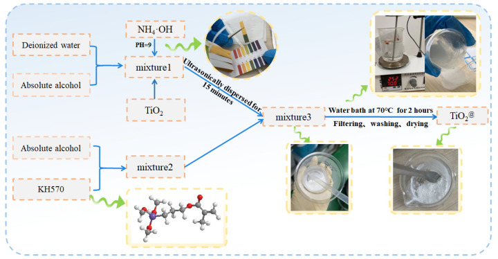 Figure 1
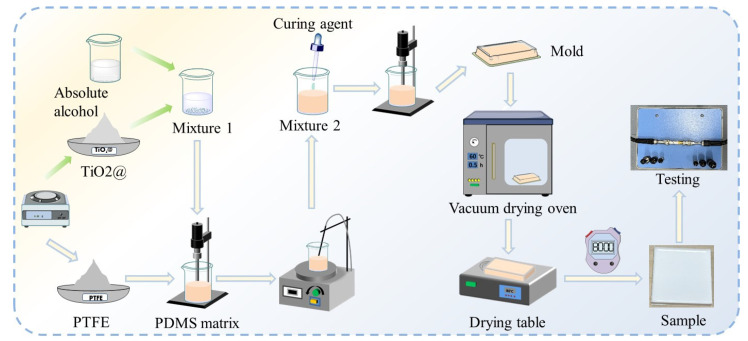 Figure 2
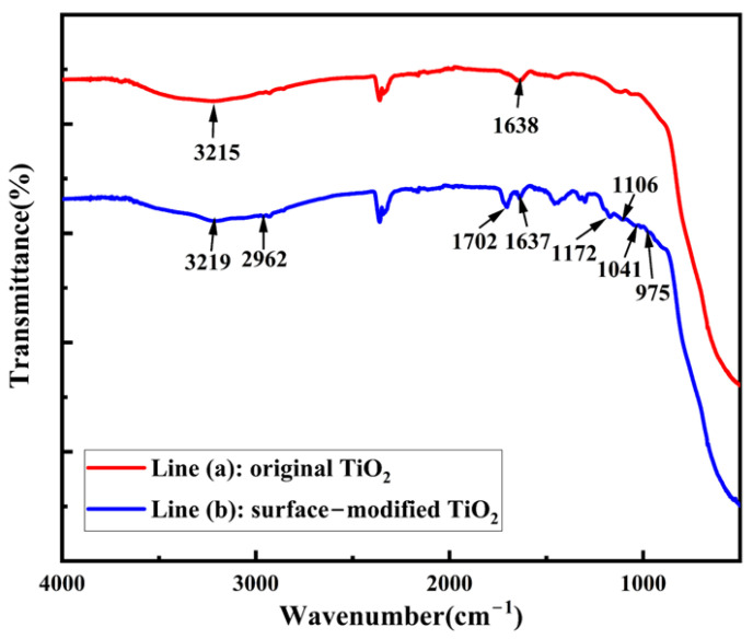 Figure 3
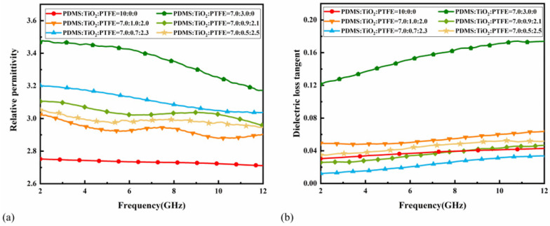 Figure 4
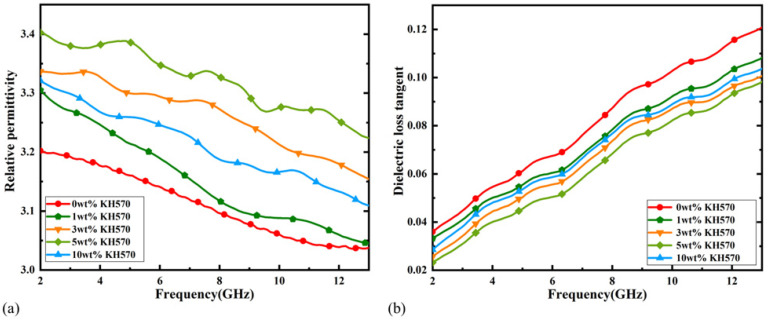 Figure 5
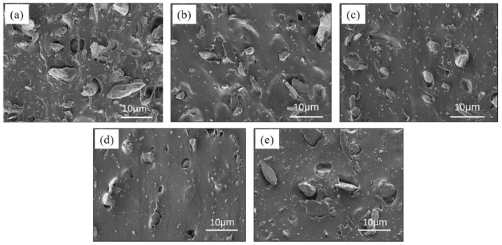 Figure 6
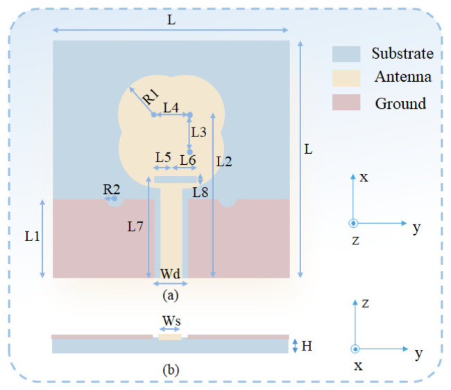 Figure 7
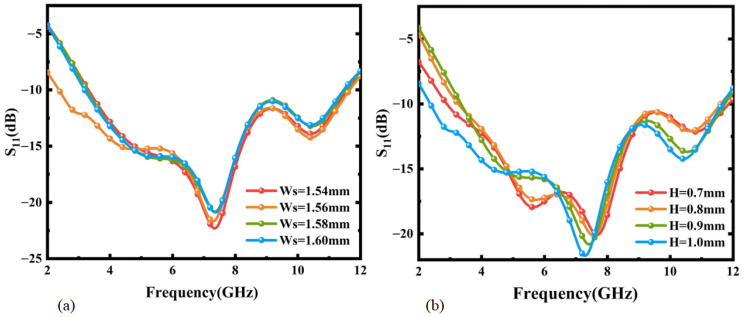 Figure 8
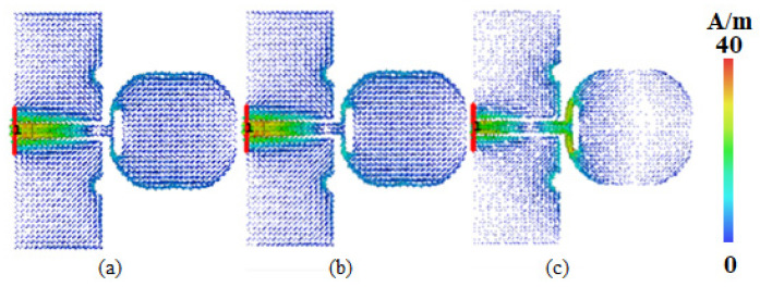 Figure 9
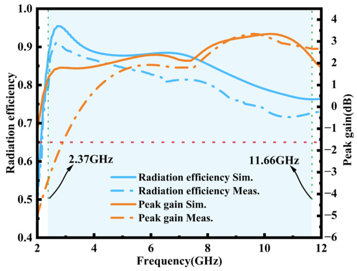 Figure 10
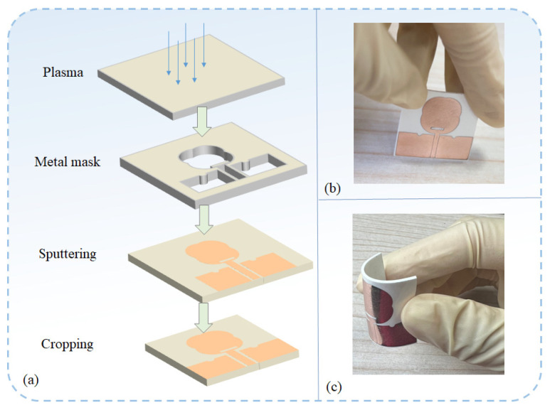 Figure 11
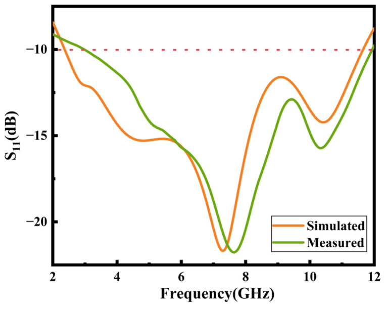 Figure 12
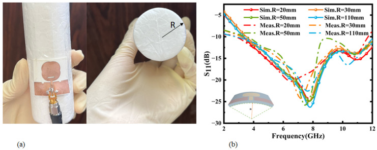 Figure 13
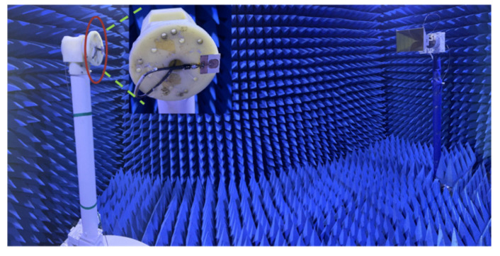 Figure 14
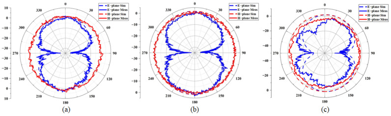 Figure 15
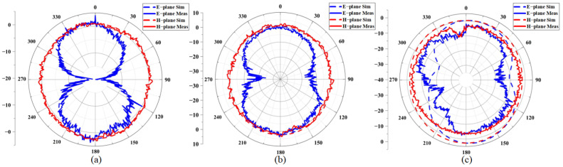 Figure 16
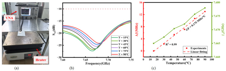 Figure 17
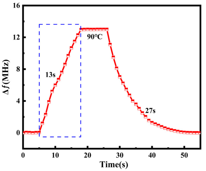 Figure 18
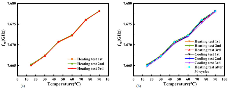 Figure 19
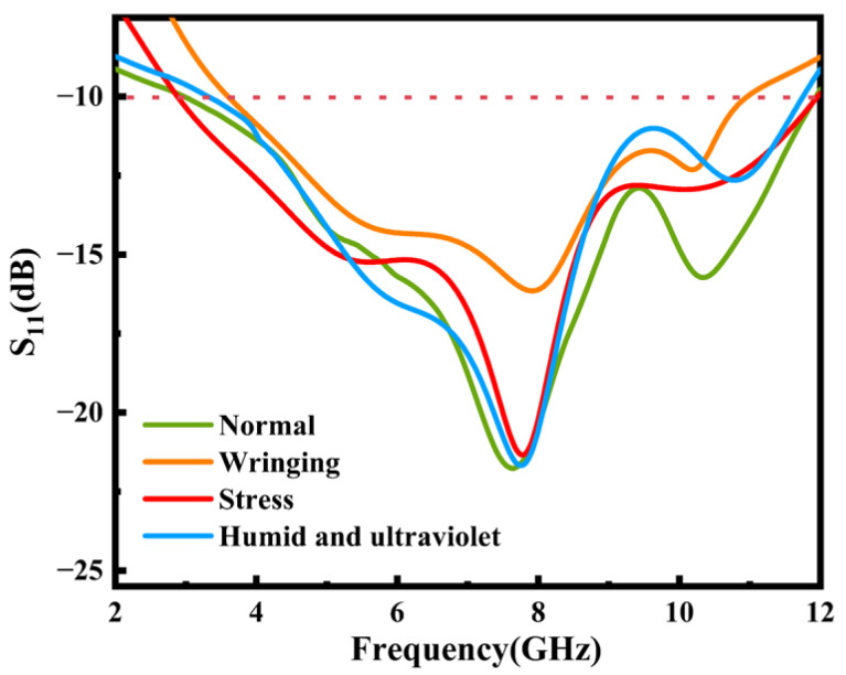 Figure 20
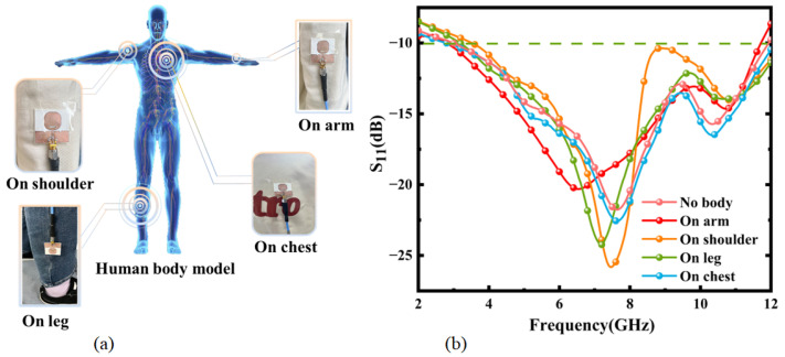 Figure 21
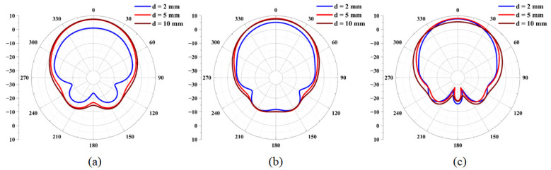 Figure 22
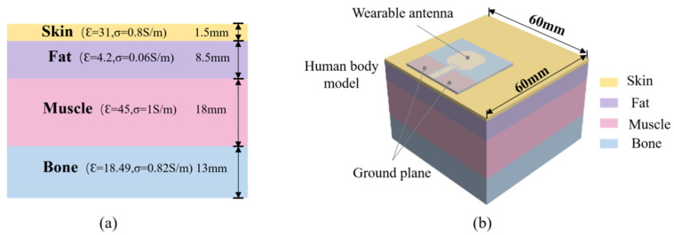 Figure 23
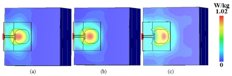 Figure 24
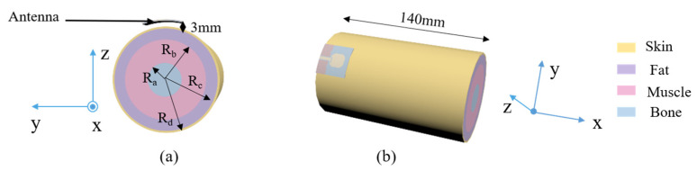 Figure 25
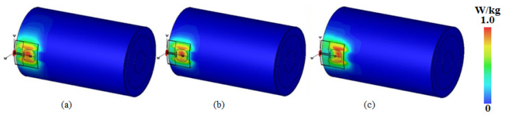 Figure 26
- —National Natural Science Foundation of China
- —Fund for the Innovation community
- —Fundamental Research Program of Shanxi Province
- —Foundation of State Key Laboratory of Dynamic Measurement Technology, North University of China
Peer Reviews
No public reviews on file for this paper yet. If you reviewed it on a platform where reviews are public (OpenReview, ICLR, NeurIPS, ICML), you can paste yours below so the community can read it here.
Videos
No videos yet. Explain this paper in a talk, walkthrough, or lecture? Add one.
Taxonomy
TopicsDielectric materials and actuators · Advanced Sensor and Energy Harvesting Materials · Electromagnetic wave absorption materials
1. Introduction
In response to the poor mobility and inefficiency of medical personnel in traditional patient care settings, the use of wearable medical devices has not only greatly improved hospital care services but also saved the time of medical personnel. Antennas play a crucial role in establishing wireless communication between wearable medical devices, which have the ability to monitor the wearer’s biosignals and communicate these data with the environment in order to provide continuous information about a person’s state of health [1,2]. Conventional antennas based on rigid substrates have limited application in wearable devices, since the basic daily activities of patients cause various physical deformations in these antennas [3,4]. In addition, wearable antennas serve as devices that radiate and receive electromagnetic waves for body-centric communication systems [5,6,7], and we must consider their safety risks to the human body in long-term electromagnetic radiation environments [8]. The above limitations pose significant challenges for the design of wearable antennas.
With the development of modern wireless communication technology, the widespread application of patient-vital-sign-monitoring systems in clinical medicine has led to increasing demand for wearable antennas, and achieving high-quality transmission of signals with minimal size while ensuring comfort has become a major challenge. It is well known that the dielectric properties of dielectric substrates have an important impact on antenna performance. A low loss tangent can reduce signal attenuation and distortion and improve the antenna’s transmission efficiency and quality [9,10], while a relatively high dielectric constant can reduce the antenna size to make the antenna structure more compact [11]. Recently, many new composite substrate materials have been developed by researchers for antenna design. For example, Vilesh et al. [12] used hot-pressed silicone rubber and low-loss BaBiLiTeO_6_ ceramics to fabricate a composite material, suitable for 5G communication systems, which can be used as a substrate for microstrip patch antennas in the high-frequency range. L. Catarinucci et al. [13] proposed using alumina oxide and barium titanate as ceramic fillers, and they synthesized ceramic-doped organosilicon structures by 3D printing molds, which offer the advantages of flexibility, conformability, and comfort. Elmobarak et al. [14] prepared flexible composite antennas with radiation efficiency above 70% by embedding highly conductive fabrics into thin composite laminates made of E-glass fiber mats and epoxy resins via an impregnation process. Compared to textiles for which the dielectric properties are not readily modifiable [15,16,17], polymer composites provide a wider range of optimization options, as the dielectric properties of the composites can be modified by filling them with functional fillers [18,19,20,21]. However, due to the difference in surface energy between nanofillers and the polymer matrix [22], direct physical blending is highly susceptible to the agglomeration phenomenon, which affects the dielectric properties of the composites [23]. Therefore, in this paper, surface modification of a doped TiO_2_ filler using a silane coupling agent (3-methacryloxypropyltrimethoxysilane, KH570) is applied to improve its dispersion state in a PDMS/PTFE blend and enhance the antenna’s substrate performance.
In this paper, a wearable ultra-wideband antenna is fabricated based on TiO_2_-PTFE-PDMS composites with an impedance bandwidth ranging from 2.37 GHz to 11.66 GHz under flat conditions and an SAR compliant with wearable standards. The dielectric properties of the dielectric substrate are enhanced through the chemical modification of TiO_2_ by KH570. At the end of this article, the details of the fabrication process for the antenna are given and the test results are presented.
2. Materials and Methods
2.1. Preparation of Substrate
2.1.1. Modification of Nano-TiO2 Powder
A mixture of 20 mL of anhydrous ethanol and deionized water was prepared according to a ratio of 1:1 by volume, and the pH of the mixture was adjusted to 9 by adding ammonia water with a mass fraction of 25%. Then, we weighed 5 g of dry TiO_2_ powder, added it to a beaker containing the mixture, and then stirred it for 20 min in a constant-temperature water bath at 70 °C so that the TiO_2_ powder was uniformly dispersed in the mixture. Next, 10 mL ethanol solution containing 0.05 g KH570 (the weight ratio of KH570/TiO_2_ varied from 1% to 10%) was slowly added to the above mixture and reacted for 1.5 h under rapid stirring at a constant temperature in a water bath. Finally, the reaction mixture was filtered, washed with ethanol several times, filtered again, and dried for 24 h in a constant-temperature drying oven at 60 °C. Then, the modified TiO_2_ powder was obtained. The modification process is shown in Figure 1.
2.1.2. Preparation of Composite Dielectric Substrate
Due to the poor grinding of the modified titanium dioxide powder, the relatively large particles mixed into PDMS would cause a bottling phenomenon, which would adversely affect the performance of the composite substrate [24,25,26,27,28,29]. The solution blending method using anhydrous ethanol as the solvent can effectively solve this problem. The specific procedure is as follows: A quantity of 0.35 g of modified TiO_2_ is mixed with 2 mL of anhydrous ethanol in a beaker. The mixture is stirred thoroughly with a glass rod until no visible particles remain. Subsequently, 1.15 g of PTFE and 3.5 g of PDMS (PDMS/TiO_2_/PTFE = 70%:7%:23%) are added, followed by ultrasonication for 30 min to ensure uniform dispersion of the components. Then, the thermostatic magnetic stirrer is heated in a water bath at 70 °C for 4 h to ensure complete volatilization of the anhydrous ethanol. The curing agent is added (the mass ratio of PDMS to the curing agent is 10:1), and the mixture is stirred with a magnetic stirrer for 20 min (at a speed of 300 rpm); then, it is poured into a mold and dried in a vacuum drying oven for 30 min for defoaming. Finally, it is transferred to a baking table for curing (at 80 °C for 80 min). A flow chart of composite dielectric substrate preparation is shown in Figure 2.
2.2. Performance Testing
2.2.1. Infrared Spectral Testing
From the comparison of spectral lines (a) and (b) in Figure 3, it can be seen that the TiO_2_ nanoparticles before and after modification had characteristic spectral bands of hydrophilic -OH groups at 3215 cm^−1^ and 3219 cm^−1^, respectively. Due to the adsorption of a large amount of water on the surface of the TiO_2_, the peaks are broad.
Moreover, the spectral line (b) produced a red-shift phenomenon owing to the formation of intermolecular or intramolecular hydrogen bonds. The absorption peaks between 800 and 500 cm^−1^ in Figure 3 belong to the characteristic peaks of TiO_2_. As line (b) shows in Figure 3, the peaks at 2962 cm^−1^, 1702 cm^−1^, and 1637 cm^−1^ correspond to the C-H, C=O, and C=C stretching vibration peaks, respectively, and the C=O band is stronger than the C=C band. The Si-O-Si bond appears at 1172 cm^−1^ [30,31], representing the condensation reaction between silanols. The absorption peaks at 1106 cm^−1^ and 1041 cm^−1^ are caused by O-Si asymmetric flexible vibration. The peak at 975 cm^−1^ is characterized by the tensile vibration of Ti-O-Si, indicating that the Si-O-C on the surface of KH570 reacts with the hydroxyl groups on the surface of titanium dioxide. Therefore, the silane coupling agent was successfully grafted onto the surface of the titanium dioxide nanoparticles.
2.2.2. Dielectric Property Testing
The dielectric properties of the composite dielectric substrate were tested using a vector network analyzer (Keysight 85054D, made by Keysight Technologies, Santa Rosa, CA, USA) with a coaxial dielectric probe kit and sequentially calibrated using open, short, and loaded calibrators to minimize the measurement errors. The final measured dielectric properties of the TiO_2_-PTFE-PDMS composite substrate with frequency for different doping ratios are shown in Figure 4a,b. The low dielectric constant and high loss of single PDMS are shown by red lines; these properties are not conducive to the miniaturization of antenna size [32]. The dielectric properties can be controlled by adjusting the proportion of doped materials.
Figure 4a,b shows that when PDMS/PTFE/TiO_2_ = 7.0:0.7:2.3, the composites had better dielectric properties; hence, this ratio was used for further studies. In order to demonstrate the effect of KH570 on the composites at this ratio, TiO_2_-PTFE-PDMS composites with different volume fractions of KH570-modified TiO_2_ filler were prepared. From Figure 5a,b, it can be seen that the modified composite material had a higher dielectric constant, which increased with an increase in the content of coupling agent KH570. When the coupling agent content was increased to 10%, the dielectric constant of the composite material decreased, while the loss tangent showed the opposite trend. The final results show that the composites containing 5 wt% KH570 had better dielectric properties.
2.2.3. SEM Characterization
A bulk composite sample was adhered to a conductive adhesive and sprayed with gold using a Quorum SC7620 sputter coater for 45 s, for which the gold spraying current was 10 mA. Then, the sample morphology was observed under the scanning electron microscope of a TESCAN MIRA LMS operating at an acceleration voltage of 3 kV. The final scanning electron microscope images are shown in Figure 6. By observing the cross-sectional SEM images of TiO_2_-PTFE-PDMS composites, it can be seen that without the coupling agent, the volume of filler particles inside the composite material was large, the internal pores were obvious, and the PDMS failed to wrap the filler well. As the coupling agent content increased, the filler size decreased, and it existed mainly in the form of small particles. In addition, the surface of the composites became flatter and smoother, with better overall dispersion. However, when the content of coupling agent was increased to 10%, there were more obvious large particles, probably because of the polymerization reaction involving the excess coupling agent. This caused the amount of coupling agent grafted on the surface of the titanium dioxide to decrease, so its compatibility with PDMS became worse.
2.3. Antenna Structure Design
The circular disk monopole antenna (CDM) is a commonly used UWB antenna with a simple structure, compact size, and excellent broadband performance. The broadband performance of this antenna is further improved by cutting rectangular and circular slots on the circular disk-shaped patch. High-frequency currents are distributed along the edge of the disk, generating electromagnetic radiation. This design reduces the radiation efficiency loss of the antenna in the high-frequency band and optimizes the performance throughout the entire frequency band. With the development of communication technology, the circular disk monopole antenna has evolved from the traditional circular shape into various shapes such as the umbrella shape [33] and Mickey Mouse [34]. Compared with that of the traditional circular disk monopole antenna, the effective length of the proposed guitar-shaped antenna’s radiator is increased by adding four circular arc curves at the edge of the radiation patch and cutting rectangular slots, without affecting the simplicity and compactness of the CDM structure. The disturbed surface current path length is increased. Bending is introduced at the corners, away from the feed line that minimizes the ground-plane radiation. With its compact size and excellent broadband performance, the guitar-shaped antenna is suitable for wireless communication devices that require miniaturization and high performance. It has broad application prospects in wireless local area networks (WLANs), wireless personal area networks (WPANs), the Scientific and Medical (ISM) band, and other frequency bands [35].
The geometry of the ultra-wideband wearable antenna designed in this paper is shown in Figure 7, with a shape similar to that of a guitar and dimensions of L × L × H. The substrate is doped with composite material, which is highly flexible, and its dielectric properties are shown in Figure 4. The coplanar waveguide feed used in the antenna simplifies the fabrication process and reduces the fabrication cost at the same time. Most importantly, the coplanar waveguide feed has a wider range of characteristic impedance and a wider operating frequency band [36].
The antenna was developed using design parameters that were calculated from the wavelength ( ) corresponding to the lower band-edge frequency of UWB, which is approximately 2.3 GHz. The approximate range of R1 and L3 can be determined using Equation (1):
The thickness of the substrate can be determined using Equation (2):
The influence of parameters such as the width Ws of the antenna feedline, the width L1 of the ground plane, the radius R2 of the semi-circular slot, and the thickness H of the substrate on the impedance bandwidth was analyzed using the simulation software Ansys HFSS 2020. Agrawall N P once pointed out in his research that the distance g between the CPW ground plane and the feed point has a significant impact on the antenna impedance bandwidth [37], and this influence is mainly reflected in the upper limit frequency. Keeping the other parameters constant, a simulation analysis was conducted on the feedline width Ws (when the width Wd of the ground plane gap is unchanged, the distance g between the CPW ground plane and the feed point increases as Ws decreases). The results are shown in Figure 8a. In the low-frequency band, when Ws = 1.56 mm, the antenna impedance bandwidth increases with an increase in Ws (i.e., as the distance g decreases, the impedance bandwidth increases). This verifies the research conducted by Agrawall N P. To maintain a wide impedance bandwidth for the antenna, according to the simulation results in Figure 8a, Ws = 1.56 mm can be selected.
By varying the thickness H of the substrate within a certain range, S11 was obtained. The results are shown in Figure 8b. It can be seen from the comparison that the influence of the substrate thickness H on the antenna impedance bandwidth is more intense in the low-frequency band and tends to stabilize in the high-frequency band. To keep the overall return loss of the antenna at a low level, based on the simulation results, H = 1 mm can be selected. The final design dimensions are summarized in Table 1.
2.3.1. Surface Current Distribution
Figure 9 shows the surface current distribution of the antenna at three frequency points of 5.25 GHz, 5.75 GHz, and 8 GHz. It can be seen that the surface current is mainly concentrated near the semicircular slot on the feeder, radiation patch edge, and grounding plane, and the maximum currents are 36 A/m, 37.5 A/m, and 39.4 A/m, respectively.
2.3.2. Radiation Efficiency and Peak Gain
Figure 10 presents the peak gain versus frequency for the antenna; it can be seen that the simulated peak gain increases with an increase in frequency, and the antenna gain is greater than zero throughout the entire UWB operating frequency band (2.3~11.66 GHz). The simulated peak gain reaches a minimum of 1.24 dB at 2.37 GHz and a maximum of 3.34 dB at 10.27 GHz. In addition, the frequency versus radiation efficiency relationship in the figure shows that the simulated radiation efficiency is more than 75% throughout the operating bandwidth, with an average radiation efficiency of about 84.46%. The simulated radiation efficiency shows a decreasing trend with increasing frequency, which is due to the fact that the patch size becomes larger than the corresponding wavelength as the frequency increases [38,39,40]. The antenna was attached to the chest to test its performance during human wearing. In the actual test, the measured values of the antenna’s radiation efficiency and peak gain decreased to varying degrees, as shown in Figure 10. The reason for the significant decrease in the measured radiation efficiency in the 6–12 GHz range is that the human body, as a lossy medium, absorbs electromagnetic energy, especially in the high-frequency band. Due to the significant resonance absorption effect of water molecules, the radiation efficiency decreases.
2.3.3. Fabrication of Antenna
In this work, a sputtering process was used to fabricate the antenna, and the overall manufacturing flow chart is shown in Figure 11a. The composite substrate exhibited hydrophobic properties, which could reduce the adhesion effect between the structures. Therefore, an oxygen plasma degumming process was first used to treat the substrate surface to improve its adhesion to copper. Then, a mask was placed on the flexible composite substrate, and the thickness of the copper film sputtered by the magnetron sputtering machine was determined according to the skin effect. Finally, the excess part of the substrate was cut off. The antenna is physically shown in Figure 11b,c.
3. Results and Applications
3.1. Antenna Frequency Test
The measured callback loss S11 when the antenna is not deformed and is in a natural state is shown in Figure 12. The simulation results show that when the antenna is not bent, the −10 dB frequency bandwidth of the antenna is 9.57 GHz. Although S11 is shifted to the high-frequency band by about 0.35 GHz in the test results, it is basically in line with the simulation curve and covers the frequency band of 2.37 GHz to 11.66 GHz with a relatively good frequency characteristic. The errors in the simulated and tested return loss curves may originate from the unstable dielectric constant due to the lack of homogeneous mixing in some areas during the processing of the substrate. Secondly, machining errors in the substrate size and the ohmic loss caused by SMA head welding will also have had a certain impact on the result.
Since the antenna is to be integrated into a garment, it will be difficult for the antenna to remain flat; therefore, its performance under bending conditions must be evaluated. The antenna was taped to cylindrical foam as shown in Figure 13a, and the antenna was tested for bending in the y-axis direction. The reason for choosing the foam was that its dielectric constant was closer to that of air. Figure 13b shows the return loss of the antenna along the y-axis for cylinders of different radii. It can be seen from the simulation results that with the change in the bending radius, the frequency point of the antenna shifted slightly, and the antenna maintained good performance. The measured results show that the bandwidth of the antenna was reduced by 5%, 14%, and 12% of the bandwidth when the antenna was on cylindrical foam with radii of 30 mm, 50 mm, and 110 mm, respectively, as compared to transmitting under flat conditions. Therefore, the antenna radiation is not proportional to the bending degree. The operating bandwidth of the antenna changes with different degrees of bending, and the function of ultra-wideband transmission can be realized at a certain degree of bending.
3.2. Radiation Performance Test of Antenna
Figure 14 shows the effect of measuring the far-field radiation pattern of an antenna in a microwave darkroom, where the antenna under test is fixed on a turntable as a receiver and a 2–18 GHz standard gain horn antenna is used as a transmitting antenna.
Figure 15a–c shows the simulated and measured direction diagrams of the antenna at three frequency points under the invisible variable state. It can be seen that the measured radiation direction diagram is basically consistent with the simulation results, there is no obvious distortion on the E-plane or the H-plane, and the antenna achieves omnidirectional radiation on the H-plane. As shown in Figure 16a–c, the radiation performance of the antenna under a bending radius of 30 mm demonstrates a slight performance degradation at 8 GHz. The antenna may show performance degradation in the high-frequency region, but it can be ignored in practical applications.
3.3. Heating Performance of Antenna
The antenna was positioned on a heater for thermal treatment as illustrated in Figure 17a; its surface temperature was elevated from 15 °C to 90 °C. A notable frequency shift near the resonant regime exhibited exceptional linearity (R^2^ = 0.99), revealing temperature-dependent resonant characteristics for in Figure 17b,c. The antenna’s superior temperature sensing performance at the resonance frequency suggests promising potential for wearable integration, particularly in scenarios requiring real-time thermal monitoring and adaptive electromagnetic responses. This thermal–frequency correlation mechanism could facilitate innovative co-design strategies for multifunctional wearable devices combining sensing and communication capabilities.
The antenna was rapidly moved from a state of 15 °C to a constant-temperature heater at 90 °C. The change in the resonant frequency of the antenna compared to that at the initial temperature is shown in Figure 18. The experiment indicated that its response time was 13 s, as shown by the blue dashed square in Figure 18.
Three cyclic repeatability tests were carried out on the proposed antenna in order to verify the reliability of the thermal sensitivity. The frequency–temperature curves during the three temperature rise processes were studied and are shown in Figure 19a. It can be seen from the figure that the coincidence of the resonant frequency points in the three experiments was relatively good. When the temperature rose from 15 °C to 90 °C, according to the repeatability error formula of the sensor, the repeatability error was calculated as (0.0131 + 0.0129 + 0.013)/3 = 0.013. The frequency–temperature curves of the three repeated temperature rise–drop tests are shown in Figure 19b. Hysteresis can be observed between the heating and cooling branches, and the heating and cooling curves do not completely overlap. The maximum deviation of the resonant frequency corresponding to the same temperature test point during the heating and cooling processes in the cycle test reached 0.0004. The hysteresis of the thermal sensitivity is as follows:
The proposed antenna was then subjected to 30 consecutive heating and cooling cycles (varying from 15 °C to 90 °C) to verify the long-term stability of the thermal sensitivity. The new curve after these cycles is shown in Figure 19b. Excellent long-term stability of the thermal sensitivity was demonstrated.
3.4. Antenna Performance on Body Models
Since various organs in the human body are lossy media [41], when exposed to the electromagnetic waves radiated by the wearable antenna, the electromagnetic field in the body will generate currents [42], which will absorb and dissipate electromagnetic energy. Therefore, it is necessary to consider whether the wearable antenna can satisfy normal communication requirements when worn on the human body. Secondly, because the antenna transmits radiation, the SAR value should be used to determine whether it is harmful to human tissues [43].
The return loss in special situations was tested in order to verify the practicability of the proposed antenna for real-world wearable applications. The antenna was attached to the inner wall of a beaker containing 4% NaCl solution to simulate the humid environment after human sweating. At the same time, a 38 W ultraviolet lamp was turned on, and a slight shift in its resonant frequency occurred after 168 h as shown in Figure 20. The observed phenomenon may be attributed to moisture-induced alterations in the surface conductivity of the antenna, potentially resulting from atmospheric water molecule adsorption. This physicochemical interaction could modify the interfacial dielectric properties, thereby compromising the antenna’s impedance matching efficiency through changes in its surface current distribution and near-field electromagnetic characteristics. In addition, the extreme environmental working state of the antenna when it is completely soaked was simulated by adding a 3 mm thick water film on the surface of the antenna. Due to the strong coupling between the antenna radiation and the high-loss water medium, the return loss curve of the antenna was significantly distorted. Consequently, substantial scattering occurred in the antenna radiation.
Furthermore, to verify the performance of the antenna under cyclic stress, a press machine was used to conduct a 30-cycle longitudinal extrusion experiment on the antenna in a flat state with a force of 2 N to simulate extrusion deformation during the wearing process. Additionally, 300 cycles of transverse manual bending experiments were carried out. The measured return loss after the stress experiment is shown in Figure 20. The shift in the resonant frequency is mainly due to the change in port impedance matching of the antenna under cyclic stress.
The antenna was fixed on the arm, shoulder, thigh, and chest of the human body using transparent tape as shown in Figure 21a for testing, and the final measured return loss results are shown in Figure 21b. The antenna was least affected when it was placed on the chest, and the resulting curve fit well with the return loss curve before wearing. When it was placed on the arm, with the largest curvature radius, only 0.48 GHz frequency deviation was generated at 2.37 GHz in the low-frequency range, and the change was lesser in the high-frequency range, which made the overall performance better. In addition, the working band of the antenna shifted due to the human body’s obstruction and scattering affecting the communication quality of the antenna during the actual measurement process. Based on the results obtained in the simulations and lab experiments, bending of the antenna, which varies with the part of the body on which the antenna is worn, does not undermine the effectiveness of the proposed wearable antenna for temperature sensing. The application of this proposed antenna on the chest will be the main direction of our future research and exploration.
In wearable communications, when antennas are attached to clothing, the distance between the antenna and the human body during movement may continuously vary, thereby altering the radiation pattern characteristics of the antenna. To investigate this effect, the antenna was positioned at distances of 2 mm, 5 mm, and 10 mm from the skin layer, and the corresponding radiation patterns were recorded at different operating frequencies, as illustrated in Figure 22. The radiation patterns of the antenna demonstrate notable stability across these varying distances. Furthermore, the influence of the human body on the antenna’s radiation gradually diminished as the separation between the antenna and the human skin increased. The radiation patterns tended to stabilize and maintain a symmetrical configuration under these conditions.
As for the SAR value for the antenna worn on the human body, the electromagnetic simulation software CST Studio Suite 2022 was used in this paper to study it, and a four-layer human tissue model (skin, fat, muscle, and bone from top to bottom) was created at a position 3 mm below the antenna, as shown in Figure 23. The electromagnetic characteristic parameters of the human tissue were in accordance with the literature when the input power was 0.02 W [44]. The final simulation results are shown in Figure 24, where the peak SARs of 1 g of tissue at 5.25 GHz, 5.75 GHz, and 8 GHz were 1.02 W/kg, 0.602 W/kg, and 0.43 W/kg, respectively.
In addition, the SAR distribution was further analyzed by simulating the antenna worn on the human arm through a multilayer cylindrical mold, as shown in Figure 25. The simulation results are shown in Figure 26, and the calculated maximum 1 g tissue average SARs were 0.998 W/kg, 0.7 W/kg, and 0.422 W/kg for 5.25 GHz, 5.75 GHz, and 8 GHz, respectively; these are far lower than the FCC limit (1.6 W/kg), and, thus, the designed ultra-wideband antenna is suitable for wearable applications.
3.5. Comparison
Table 2 compares the proposed antenna with some previous works, and the results show that the flexible substrate fabricated with doped polymer material in this paper achieves higher radiation efficiency with a smaller size. Also, it shows better performance in terms of its impedance bandwidth.
4. Conclusions
An ultra-wideband antenna based on a flexible composite dielectric substrate was proposed, in which the dielectric modulation of the substrate was realized by doping different ratios of fillers into the matrix. The use of silane coupling agent improved the dispersion of filler TiO_2_ in the matrix, which further enhanced the dielectric properties of the substrate and expanded the antenna’s potential for wearable applications. A miniaturized ultra-wideband antenna was designed and machined in order to verify the utility and feasibility of the new substrate. By using a magnetron sputtering process, the adhesion and structural accuracy of the metal structure on the antenna surface were improved. The antenna demonstrated significant potential for future applications in detecting environmental thermal changes. In order to test its usage in a real environment, the radiation performance of the antenna under bending conditions was simulated and tested by means of cylindrical foams with different curvatures. In addition, the safety requirements were satisfied, as the SAR distribution was further analyzed by simulating the antenna worn on the human arm through a multilayer cylindrical mold. Therefore, the antenna, made of a dielectric substrate with higher toughness, a higher dielectric constant, and a lower loss angle tangent, is suitable for ultra-wideband wireless communication, which provides a direction for the integration of antennas with medical devices.
The reference list from the paper itself. Each links out to its DOI / PubMed record.
- 1Mohamadzade B. Hashmi R.M. Simorangkir R.B.V.B. Gharaei R. Ur Rehman S. Abbasi Q.H. Recent Advances in Fabrication Methods for Flexible Antennas in Wearable Devices: State of the Art Sensors 201919231210.3390/s 1910231231109158 PMC 6567739 · doi ↗ · pubmed ↗
- 2Hertleer C. Tronquo A. Rogier H. Vallozzi L. Van Langenhove L. Aperture-Coupled Patch Antenna for Integration Into Wearable Textile Systems IEEE Antennas Wirel. Propag. Lett.2007639239510.1109/LAWP.2007.903498 · doi ↗
- 3Khaleel H.R. Al-Rizzo H.M. Rucker D.G. Compact Polyimide-Based Antennas for Flexible Displays J. Disp. Technol.20128919710.1109/JDT.2011.2164235 · doi ↗
- 4Caldeira J.M. Rodrigues J.J. Lorenz P. Toward ubiquitous mobility solutions for body sensor networks on healthcare IEEE Commun. Mag.20125010811510.1109/MCOM.2012.6194390 · doi ↗
- 5Gao G.-P. Hu B. Wang S.F. Yang C. Wearable Circular Ring Slot Antenna With EBG Structure for Wireless Body Area Network IEEE Antennas Wirel. Propag. Lett.20181743443710.1109/LAWP.2018.2794061 · doi ↗
- 6Stoppa M. Chiolerio A. Wearable Electronics and Smart Textiles: A Critical Review Sensors 201414119571199210.3390/s 14071195725004153 PMC 4168435 · doi ↗ · pubmed ↗
- 7Paracha K.N. Rahim S.K.A. Soh P.J. Kamarudin M.R. Tan K.-G. Lo Y.C. Islam M.T. A Low Profile, Dual-band, Dual Polarized Antenna for Indoor/Outdoor Wearable Application IEEE Access 20197332773328810.1109/ACCESS.2019.2894330 · doi ↗
- 8Zhang K. Soh P.J. Yan S. Meta-Wearable Antennas—A Review of Metamaterial Based Antennas in Wireless Body Area Networks Materials 20211414910.3390/ma 14010149 PMC 779516433396333 · doi ↗ · pubmed ↗