Comparison Of Transfer Accuracy Among Hexed Implant Mounts, Clips Impression Copings, And Open-Tray Impression Copings at Different Implant Angulations: An In Vitro Study
Merna M. Seif, Ahmed A. Abdel Hakim, Hassan M. Abouelkheir, Rana A. Negm

TL;DR
This study compares the accuracy of different dental impression techniques for transferring implant positions at various angles.
Contribution
The study provides empirical evidence on the performance of three impression coping types at different implant angulations.
Findings
Open-tray and clips copings showed reliable accuracy for implants up to 25° angulation.
Hexed implant mounts showed increased deviations at 25° angulation compared to other methods.
All methods performed similarly for straight (0°) implants.
Abstract
Accurate impression registration is essential for transferring the three-dimensional (3D) implant position to the definitive cast, ensuring passivity of the final prosthesis. Various impression techniques have been developed to optimize accuracy, particularly for angulated implants. This study aimed to evaluate and compare the accuracy of open-tray impression copings, clips impression copings, and hexed implant mounts in transferring implant positions for both straight and angulated implants. Five implants with different angulations (three at 0°, one at 15°, and one at 25°) were placed in an epoxy resin model, reflecting angulations commonly encountered in clinical practice. Thirty impressions were made using three types of impression copings: open-tray, clips (closed-tray), and hexed implant mounts (closed-tray), with ten impressions per group. Impressions were poured, and CBCT scans…
Genes, proteins, chemicals, diseases, species, mutations and cell lines named across the full text — each resolved to its canonical identifier and authoritative record.
Click any figure to enlarge with its caption.
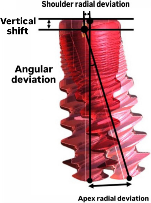 Figure 10
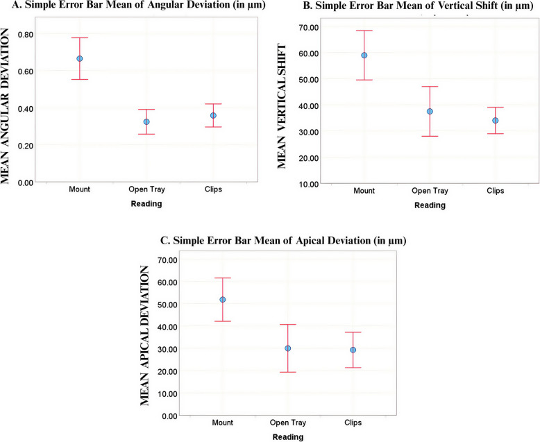 Figure 11
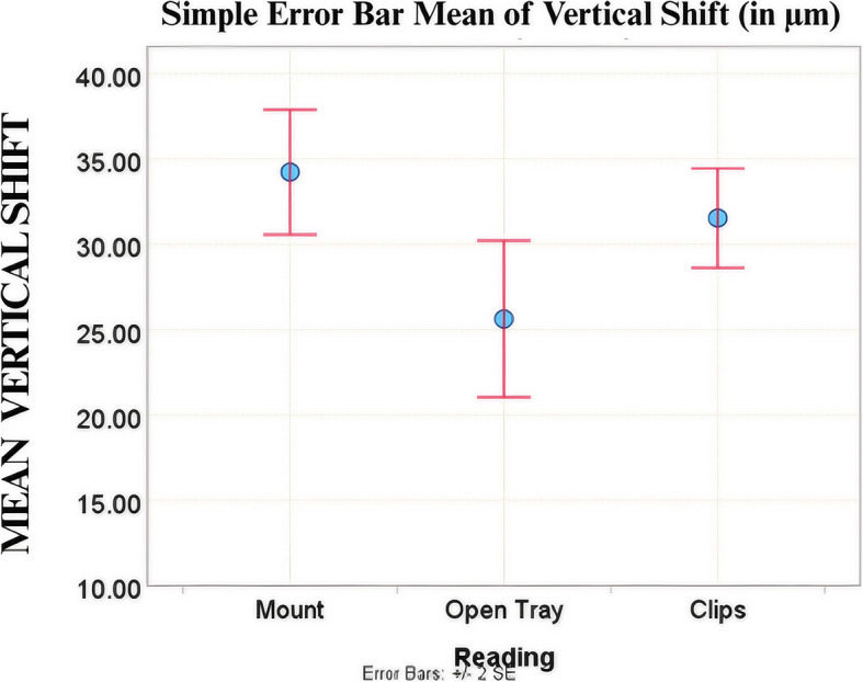 Figure 12
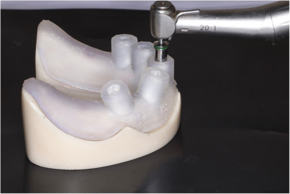 Figure 1
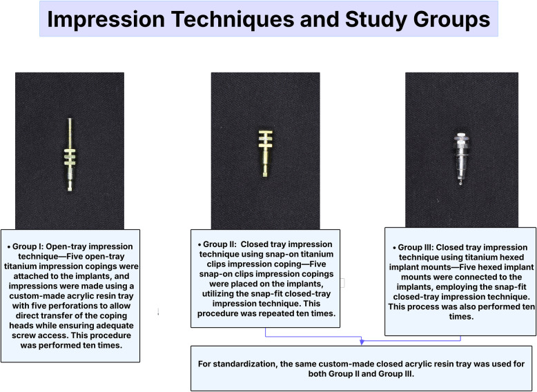 Figure 2
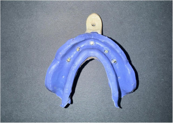 Figure 3
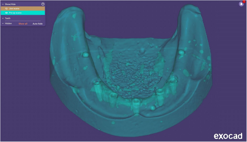 Figure 4
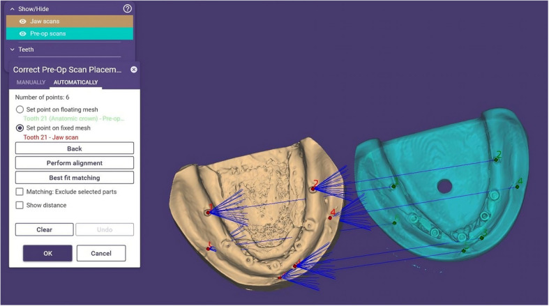 Figure 5
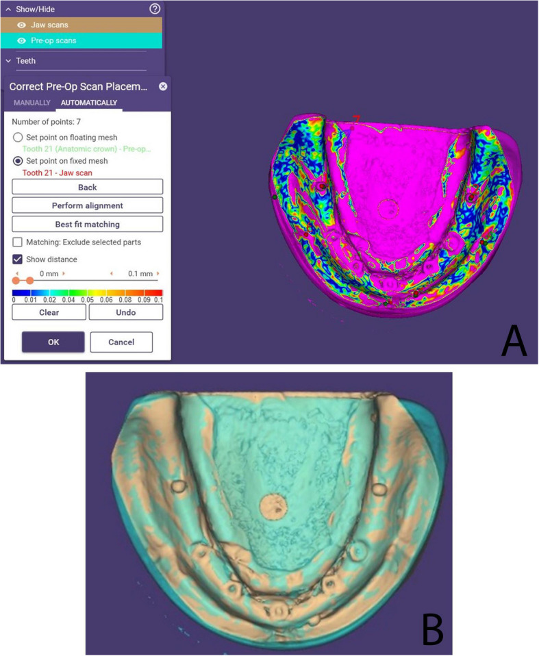 Figure 6
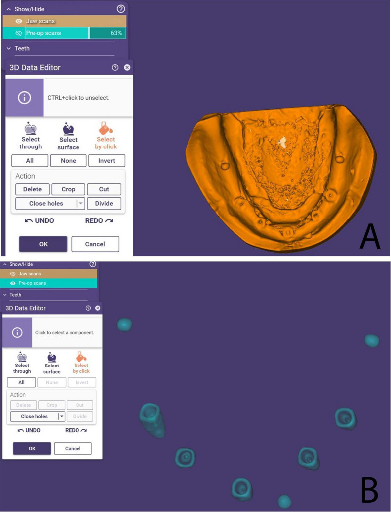 Figure 7
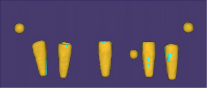 Figure 8
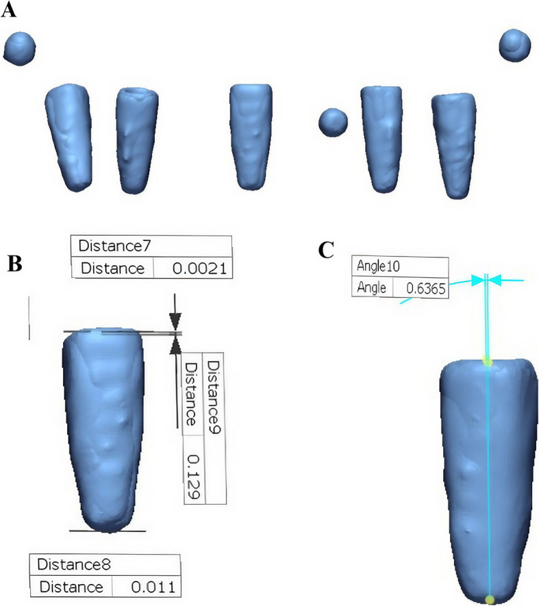 Figure 9
- —Alexandria University
Peer Reviews
No public reviews on file for this paper yet. If you reviewed it on a platform where reviews are public (OpenReview, ICLR, NeurIPS, ICML), you can paste yours below so the community can read it here.
Videos
No videos yet. Explain this paper in a talk, walkthrough, or lecture? Add one.
Taxonomy
TopicsDental Implant Techniques and Outcomes · Dental materials and restorations · Orthopaedic implants and arthroplasty
Background
The accuracy of impression registration is crucial in implant prosthetic treatment, directly affecting the master cast precision and passive fit of the prosthesis [1, 2]. Several factors influence accuracy, including the impression technique (direct or indirect), implant angulation, coping geometry, the type of prosthetic connection, and material properties [3–8]. While titanium remains the standard material for implant components, newer biomaterials such as polyetheretherketone (PEEK) are increasingly being introduced, with their distinct properties potentially influencing impression accuracy [9]. Any inaccuracies can compromise passive fit and long-term clinical success [10–12].
Achieving absolute passive fit remains a challenge in clinical practice [8, 13]. Unlike natural teeth, which exhibit mobility due to the periodontal ligament, dental implants are osseointegrated with minimal movement (~ 10 μm) [14]. Misfit can introduce stresses, causing complications such as screw loosening, fractures, or loss of osseointegration [15, 16]. Discrepancies as small as 50 μm can be detected in accurate impressions [17], with angular deviations of around 0.4° considered acceptable [18, 19].
Digital technology has significantly transformed prosthodontics, particularly with the use of intraoral and desktop scanners for impression registration. While these methods are effective for partial-arch impressions, full-arch scans remain challenging due to inconsistent results and difficulties in accurately merging images, especially in edentulous cases [20–26]. Consequently, conventional impression techniques often yield more predictable outcomes than digital methods in full-arch scenarios [27].
To optimize accuracy, various techniques have been developed. The open-tray technique improves accuracy by directly picking up the coping, but securing the implant analog can introduce minor inaccuracies [1, 28]. On the other hand, the closed-tray technique is beneficial in limited inter-arch space or exaggerated gag reflex; however, it is prone to misalignment [1, 28]. Both methods involve repeated screwing and unscrewing, which can lead to discomfort and potential deformation, thereby affecting accuracy [29].
The International Team for Implantology (ITI) introduced the snap-on (press-fit) technique, combining the benefits of both methods. It eliminates large tray openings and extended screws, improving efficiency and comfort; however, inaccuracies like plastic deformation may still occur [29, 30].
Hexed snap copings and hexed implant mounts, utilizing the same press-fit principle, have been developed to enhance cost-effectiveness and accuracy. Given the discrepancies in previous studies, this research aims to compare the precision of open-tray and snap-on techniques using clips impression copings and hexed implant mounts. The null hypothesis proposes no significant differences in shoulder radial deviation, apical radial deviation, angular deviation, and vertical shift among the three coping types.
Methods
Reference Model Fabrication
A mandibular edentulous epoxy resin model was scanned using a laboratory optical scanner (Medit T710, South Korea), in which the resulting STL file was imported into virtual implant planning software (Bluesky Bio, Illinois, United States) to facilitate precise placement of five implants (Biodem Implants, Düsseldorf, Germany) of equal size (diameter:3.8 mm/10 mm length). Implant positioning was planned as follows: one implant at the midline with a 0° angulation, two implants on the left side (canine and second premolar regions) also placed at 0° angulation, while on the right side, one implant was positioned in the canine region at a 15° mesial angulation, and another in the second premolar region at a 15° distal angulation with an additional 10° buccal angulation. A sleeveless surgical guide was printed using a 3D printer (Formlabs Form 4, United States) and was utilized for site marking and drilling before securing all five implants in their preplanned positions (Fig. 1), thereby establishing the reference model for the study.Fig. 1. Implant drilling using 3D printed surgical guide
Impression Techniques and Study Groups
All impression copings and implant mounts used in this study were made of titanium to ensure consistency in material properties across groups. Samples were divided into three groups based on the impression technique. Group I used the open-tray method with titanium open-tray copings, while Groups II and III followed the closed-tray technique using snap-on titanium clips and hexed implant mounts, respectively. Each group comprised ten impressions. For Group I, a custom acrylic resin tray with large openings to accommodate the long coping screws was utilized. On the other hand, Groups II and III used the same closed tray for standardization. An illustration of the grouping is provided in (Fig. 2).Fig. 2. Study groups and impression techniques. Three impression techniques were evaluated: Group I used an open-tray method with open-tray titanium copings; Groups II and III employed closed-tray techniques with snap-on titanium clips and hexed implant mounts, respectively. All impressions were made ten times. A custom-made acrylic resin tray was used for Group I, while a standardized closed-tray was used for Groups II and III
Sample Size Calculation
The sample size was estimated assuming a 5% alpha error (α = 0.05) and 80% study power (β = 0.20). A 95% confidence level was used to detect differences in accuracy between the open-tray and snap-on impression methods. Based on these parameters, the required sample size was determined to ensure adequate statistical power for the comparisons.
Standardization of Impression Removal
To ensure uniformity in the force and direction of impression tray removal, a hole was incorporated into the base of the reference model to allow secure attachment to a Universal Testing Machine (UTM) (5ST, Tinius Olsen, England), which enabled controlled vertical removal of the impressions perpendicular to the occlusal plane at a constant crosshead speed of 5 mm/min. A custom metal attachment was designed and fixed to the tray to provide a stable connection to the UTM.
Reference Model Preparation for Digital Superimposition
Three Ø2-mm metal beads were incorporated into the reference model, two of which were placed on the posterior crest of the ridge and one on the labial side, to serve as fixed reference points for digital superimposition and enable precise assessment of implant position deviations.
Impression Material and Casts Fabrication
All impression copings were splinted using low-shrinkage, autopolymerizing resin (Duralay Inlay Pattern Resin, Reliance Dental Manufacturing LLC, United States). To minimize polymerization shrinkage effects, the splints were sectioned after 24 h, carefully realigned, reconnected, and then left to cure for an additional 24 h before impression registration. [31–33] Vinyl polyether siloxane (VPES) medium-viscosity monophasic precision impression material (Identium Medium, Kettenbach SNC, France) was used for all impressions (Fig. 3), where a thin layer of VPES adhesive (Identium® Adhesive, Kettenbach GmbH & Co. KG., Germany) was applied to the impression tray and allowed to dry for five minutes. Subsequently, the impression material was dispensed from the Automixer Cartridge System (Kettenbach GmbH & Co. KG, Eschenburg, Germany) into the custom tray and around the transfer copings, after which the tray was positioned onto the reference model. The impression was removed vertically as previously described using the UTM at a constant crosshead speed of 5 mm/min.Fig. 3. Open-tray implant impression. Impression copings are captured in VPES, showing depressions that will accommodate metal beads used for digital superimposition
Following impression procedures, all impressions were poured using extra-hard Type IV dental stone (Zermakh Elite Rock, Italy). CBCT scans of the reference model and all casts were acquired using an imaging system (Vatech Green X, Gyeonggi-do, South Korea) equipped with a metal artifact reduction (MAR) feature, with a field of view (FOV) of 8 × 5 cm and a voxel size of 0.2 mm. The obtained DICOM files were subsequently converted into STL format using 3D visualization software (3D Slicer, Massachusetts, United States). For standardization, all steps were performed by the same operator to minimize inter-operator variability.
Implant Position Accuracy Assessment
Metal bead locations served as fixed reference points during alignment. Each of the three metal beads was initially secured to the reference model using cyanoacrylate (CYACEM, Bredent Medical GmbH & Co. KG, Senden, Germany) and verified for stability. During cast fabrication, beads of identical size were inserted into the corresponding negative spaces within the impression and fixed with cyanoacrylate. Gentle vibration was applied to ensure they remained stationary. After the cast had set, the stability of the beads was rechecked, and they were manually repositioned into the corresponding indentations of the poured cast and re-secured with cyanoacrylate. This approach enabled consistent and precise reference points for accurate measurement of implant deviations.
For digital analysis, two STL files were generated for each cast and the reference model: one representing the complete model (resin or stone) and another containing only the five implants and three metal beads (Fig. 4). Alignment was performed using ExoCAD DentalCAD 2016 (exocad GmbH, Darmstadt, Germany) by importing these STL files. Initial multi-point alignment utilized shared anatomical landmarks (e.g., arch form, ridge contour, and freni) to ensure stable superimposition between casts and the reference model (Fig. 5). Once alignment was confirmed via best-fit matching (Fig. 6A, B), non-essential scan data (resin or stone model) were digitally removed, isolating the five implants and metal beads (Fig. 7A, B).Fig. 4. Relation between the cast STL File and the implants and metal beads STL fileFig. 5Alignment of the reference model and stone cast using multiple landmarks and metal beadsFig. 6(A) Best-fit matching; (B) Alignment based on common landmarksFig. 7Removal of resin and stone models after alignment, leaving implants and metal beads
This process minimized registration error by relying on the complete model geometry, compensating for minor manual variations in beads placement. The aligned implants-and-beads STL files (Fig. 8) were then exported from ExoCAD and imported into reverse engineering software (Geomagic Control X, 3D Systems, Rock Hill, SC, USA) for quantitative measurement of implant positional deviations (Fig. 9). This alignment approach corrected small misalignments by utilizing stable anatomical features, enhancing accuracy and reducing distortion bias.Fig. 8. Aligned implants and metal beads STL files ready for import to Geomagic Control XFig. 9(A) Alignment of the reference image and the sample image, followed by measurement of (B) linear and (C) angular implant deviations
Implant position accuracy was evaluated by assessing radial deviation, angular deviation, and vertical shift, with all values reported in microns. A visual representation of these measurements is provided (Fig. 10). Radial deviation, defined as the lateral displacement of the implant axis perpendicular to that of the reference model, was evaluated at two locations: the implant shoulder (shoulder radial deviation) and the implant apex (apex radial deviation). Angular deviation referred to the angle between the implant axes of the reference model and the poured casts. Vertical shift denoted the difference in height of the implant platform between the reference model and the casts.Fig. 10. Visual illustration of the measured deviation parameters
Statistical Analysis
Statistical analyses were performed using IBM SPSS Statistics version 27.0 (Armonk, NY, USA). Descriptive statistical measures, including mean, median, standard deviation, skewness, kurtosis, and confidence intervals, were calculated to summarize the data and assess distribution characteristics. To address potential distortions due to outliers, Huber’s M-estimator was employed as a robust measure of central tendency. Data distribution was further evaluated through visual inspection using histograms and quantile–quantile (Q-Q) plots.
Inferential analysis, One-Way ANOVA was used to assess differences among the three impression coping groups (mount, open-tray, and clips), with a significance threshold set at p < 0.05. When significant group differences were identified, post hoc comparisons were performed. Tukey’s HSD test was applied under the assumption of homogeneity of variances, while the Games-Howell test was used when this assumption was violated. Effect sizes were calculated using eta-squared (η^2^) to evaluate the practical significance of group differences.
Results
The results showed a statistically significant difference in angular deviation (p < 0.001), apical deviation (p = 0.003), and vertical shift (p < 0.001) for Implant 1 (25°), and a statistically significant difference (p = 0.011) in vertical shift for Implant 2 (15°). In contrast, no significant differences were observed among the three impression coping techniques for any of the four parameters (coronal, apical, angular deviations, and vertical shift) at Implants 3, 4, and 5 (0° or straight implants). These findings are detailed in Table 1. Table 1. One-way ANOVA of Deviation Measures across The Three Groups of Impression Copings (in μm)Measure ImplantOne-way ANOVAMountOpen TrayClipsF(df1,df2)p**η^2^Angle Deviation 10.67 ± 0.1780.32 ± 0.1050.36 ± 0.09820.180(2,27)^a^ < 0.001^^0.599 20.34 ± 0.1040.25 ± 0.0770.30 ± 0.0573.099(2,27)^a^0.0610.187 30.34 ± 0.1790.21 ± 0.0630.22 ± 0.0862.039(2,16.313)^b^0.1620.199 40.29 ± 0.1490.19 ± 0.0730.19 ± 0.1201.748(2,16.429)^b^0.2050.140 50.29 ± 0.1880.16 ± 0.0910.23 ± 0.1162.230(2,27)^a^0.1270.142Shoulder Deviation** 143.10 ± 5.52538.70 ± 6.35038.89 ± 3.8232.177(2,27)^a^0.1330.279 231.72 ± 9.32131.70 ± 8.76825.54 ± 10.5320.971(2,27)^a^0.3910.065 325.26 ± 11.21720.64 ± 11.85916.24 ± 7.1001.927(2,27)^a^0.1650.073 414.54 ± 8.23418.58 ± 9.30118.31 ± 10.6630.570(2,27)^a^0.5720.038 521.69 ± 12.29017.77 ± 10.01913.71 ± 3.2742.415(2,13.851)^b^0.1260.039Apical Deviation 151.85 ± 15.36229.99 ± 16.90229.28 ± 12.5457.270(2,27)^a^0.003^^0.350 232.49 ± 10.47026.27 ± 6.64428.52 ± 7.1081.454(2,27)^a^0.2510.097 324.19 ± 18.83916.33 ± 5.36118.56 ± 8.2330.912(2,15.751)^b^0.4220.075 432.85 ± 21.90318.63 ± 8.83222.81 ± 10.6561.870(2,16.690)^b^0.1850.150 524.41 ± 17.08823.13 ± 9.83919.66 ± 6.4400.624(2,16.129)^b^0.5480.030Vertical Shift** 158.97 ± 14.90337.50 ± 15.04434.02 ± 7.98610.692(2,27)^a^ < 0.001^^0.442 234.23 ± 5.78325.63 ± 7.25531.54 ± 4.6015.417(2,27)^a^0.011^^0.286 327.60 ± 13.22220.25 ± 15.49127.23 ± 13.7130.853(2,27)^a^0.4370.059 431.04 ± 20.90420.81 ± 16.60519.44 ± 14.0541.324(2,27)^a^0.2830.089 527.82 ± 18.50715.70 ± 7.63921.77 ± 10.6522.308(2,16.486)0.1310.137Significant at 0.05Significant at 0.01^a^F statistic from ANOVA Table.^b^W statistic (Welch) from Robust Tests of Equality of Means Table
Upon pairwise comparison at Implant 1, the hexed implant mount exhibited higher angular deviation (0.67° ± 0.178°), apical deviation (51.85 ± 15.362 μm), and vertical shift (58.97 ± 14.903 μm) values compared to both the open-tray (0.32° ± 0.105°), (29.99μm ± 16.902 μm), and (37.50μm ± 15.044μm); and clips impression copings (0.36° ± 0.098°), (29.28μm ± 12.545μm), and (34.02μm ± 7.986 μm), respectively (Fig. 11). However, no significant difference was found between the open-tray and clips impression copings for any parameter. At Implant 2, a greater vertical shift was observed in the hexed implant mount group (34.23 ± 5.783μm) compared to the open-tray impression coping (25.63 ± 7.255μm) (Fig. 12). No significant differences were found in apical, coronal, or angular deviations between the hexed implant mount and the open-tray coping. Likewise, no differences were observed between the clips and open-tray copings for any of the parameters. These findings are detailed in Table 2.Fig. 11(A)Angular Deviation, (B) Vertical Shift, and (C) Apical Deviation Values at Implant 1 (25°)Fig. 12. Vertical Shift Values in Vertical Group at Implant 2 (15°)Table 2. Post Hoc Multiple Comparisons of Deviation Measures across The Three Groups of Impression CopingsImplantReading PairAngleShoulderApicalVertical ShiftMDSigMDSigMDSigMDSig1Mount < – > Open Tray0.34**** < 0.001^^4.410.17421.850.008**^^**21.460.003^^**Mount < – > Clips0.31**** < 0.001^^4.210.20122.570.006**^^24.95 < 0.001**^****^Clips < – > Open Tray0.030.8350.200.996−0.710.994−3.490.8232Mount < – > Open Tray0.090.049**^^0.021.0006.220.2308.600.009^^Mount < – > Clips0.040.4615.180.4583.970.5382.690.579Clips < – > Open Tray0.050.415−5.160.4612.250.8165.910.087**3*Mount < – > Open Tray0.120.1494.620.5797.870.4417.350.487Mount < – > Clips0.120.1789.020.1415.630.6710.360.998Clips < – > Open Tray0.000.996−4.400.6102.240.7566.980.5214****Mount < – > Open Tray0.100.183−4.030.61114.220.18010.230.400Mount < – > Clips0.090.300−3.770.65010.040.41811.600.312Clips < – > Open Tray0.010.990−0.260.9984.180.614−1.370.9835****Mount < – > Open Tray0.130.1073.920.7191.290.97712.120.177Mount < – > Clips0.060.6307.980.1654.750.6976.050.652Clips < – > Open Tray0.070.473−4.060.468−3.470.6296.070.333**. MD is significant at the 0.05 level****. MD is significant at the 0.01 level*
Discussion
Accurate implant impressions are crucial for transferring implant positions to the definitive cast, ensuring the passivity of implant-supported prostheses [1, 2]. This passivity ensures restoration longevity and maintains peri-implant tissue health. Impression accuracy is influenced by factors such as the type and material of the coping, splinting, implant angulation, and the number of implants [5–7, 17]. The study compared the accuracy of open-tray, clips, and hexed implant mounts in transferring implant positions for both straight and angulated implants. Statistically significant differences were found across all measured parameters (shoulder and apical radial deviation, angular deviation, and vertical shift); consequently, the null hypothesis has been rejected.
These findings highlight that impression coping type significantly influences implant position transfer accuracy, potentially affecting the passive fit and long-term clinical success of the prosthesis. The varying accuracy among open-tray, snap-on clips, and hexed implant mounts highlights the importance of selecting an impression technique suitable to specific clinical situations.
To assess the impact of implant angulation on impression accuracy, five implants were positioned in a mandibular epoxy resin model to replicate clinical conditions and stabilize the dental implants. The epoxy resin was chosen for its superior mechanical properties, dimensional stability, and a modulus of elasticity that closely resembles that of human bone [34, 35].
Accurate implant placement at the preplanned angulations was achieved using a surgical guide. Surgical guides have been shown to significantly enhance the precision of implant positioning [36–38]. Furthermore, recent studies have reported that sleeveless surgical guides, as utilized in the present study, demonstrate comparable accuracy to conventional guides equipped with metal sleeves [39, 40]. Recent advancements in digitally guided workflows have further optimized impression accuracy and prosthesis fit. For instance, the use of digital implant planning and transfer techniques has been shown to improve clinical outcomes and workflow efficiency [20, 27].
On the left side of the model, three straight implants were placed, including one at the midline, to assess whether its proximity to an adjacent angulated implant would influence its transfer accuracy. On the right side, two angulated implants were placed at 25° (15° distal and 10° buccal) and 15° mesial to create maximal divergence and assess the impact of high angulation on impression accuracy. A major concern in implant prosthodontics is achieving accurate impressions for angulated implants. Due to factors such as bone resorption, poor bone quality, hard tissue undercuts, and esthetics, achieving parallel implant placement can be challenging. In such cases, implants are often placed at buccolingual or mesiodistal angles. Impressions of angulated implants may be less accurate than those of parallel implants [6, 7, 17]. Previous studies, including those by Tsagkalidis et al. [41] and Tafti et al. [42], have examined the effect of 0°, 15°, and 25° implant angulation on impression accuracy, as these angles are frequently encountered in clinical practice.
In the present study, open-tray impression copings were used for their superior transfer accuracy [13, 43, 44]. However, they can be time-consuming and uncomfortable for both the patient and clinician, especially in cases with limited interarch space. To address this, clips impression copings and hexed implant mounts, used in the study, are classified as pick-up closed-tray implant-level impression copings. These copings remain within the impression, eliminating the need for unscrewing and repositioning of the copings, which could otherwise introduce positional inaccuracies. They combine the advantages of open-tray copings (direct), such as preventing repositioning errors, with those of closed-tray copings (indirect), including ease of use, time efficiency, improved patient comfort, and better accessibility in limited interarch spaces [1, 28, 45].
Clips impression copings connect to the abutment-implant interface with a frictional fit, and their short connection helps prevent displacement, particularly in angulated implants. A hexed implant mount, which also connects by frictional fit, differs from the clips impression coping in having a longer connection. While most previous research has focused on open-tray (direct) and closed-tray (indirect) transfer impression copings, pick-up closed-tray copings, as utilized in this study, have been insufficiently addressed.
The impression copings and implant mounts utilized in this study were made of titanium, which provide greater accuracy than plastic copings. Walker et al. [30] found that the metal copings technique yielded more accurate casts than the plastic caps technique. Additionally, Arieli et al. [46] concluded that plastic snap-on copings were less accurate due to dimensional distortions caused by acrylic resin shrinkage during splinting—a problem that persisted even after sectioning and rejoining the caps. The resilience of plastic components in closed-tray snap-on techniques may also be contributed to deformation from polymerization shrinkage [46].
Splinting was performed using low-shrinkage autopolymerizing resin to minimize micromovements of the copings during impression registration of multiple and angulated implants. The splinted copings were sectioned and reconnected to counteract polymerization shrinkage. Sectioning was performed 24 h after splinting to allow for most of the polymerization shrinkage to occur. Previous studies indicate that approximately 80% of shrinkage happens within the first 17 min, with total volumetric shrinkage reaching about 7.9% over 24 h. [31–33] Adell et al. [47] emphasized the significance of intraorally splinting impression copings before impression making. Similarly, Vigolo et al. [48] reported that definitive casts exhibited greater accuracy when impression copings were splinted using autopolymerizing resin. To further minimize polymerization shrinkage, it has been recommended to section and rejoin the autopolymerizing resin splint [49, 50].
VPES medium-viscosity, monophasic precision impression material (Identium Medium, Kettenbach SNC, France) was used to enhance accuracy. This material offers improved elasticity, making it particularly suitable for angulated implants, while its increased stiffness prevents tearing during impression removal. A systematic review by Saini et al. [51] found that VPES has significantly higher tensile strength and fewer defects compared to polyether (PE) and polyvinyl siloxane (PVS). VPES also demonstrated superior wettability and a lower contact angle with water, making it especially effective in moist clinical environments [52]. Singer et al. [53] and Rose et al. [54] further supported these findings, noting that VPES produced markedly better dimensional accuracy than both PE and PVS.
In the present study, a UTM was employed to control and standardize both the direction and force of tray removal, which was performed along a vertical axis. Terry et al. [55] introduced posterior lateral detachment wings on custom trays to achieve uniform axial traction during removal, while Geramipanah et al. [56] used extensions connected to a vertical surveyor rod to ensure controlled vertical detachment. In line with previous studies evaluating the tensile strength of impression materials, the crosshead speed of the universal testing machine was set at 5 mm/min [52, 57].
Implant position accuracy was evaluated by obtaining CBCT images of both the reference model and the poured casts. These images were superimposed in order to assess angular deviation, shoulder and apex radial deviation, and vertical shift. This method has been widely adopted in previous studies, as described by Li et al. [58] and Yi et al. [59], in which CBCT images were converted into STL files and analyzed using reverse engineering software such as Geomagic Control X (3D Systems, Rock Hill, SC, USA). Similarly, D’haese et al. [60] used the same software to compare the accuracy of conventional and digital impressions.
Open-tray impression copings demonstrated superior accuracy compared to hexed implant mounts in transferring the position of implant 1 (25°), particularly in terms of angular deviation, apical radial deviation, and vertical shift. For implant 2 (15°), they also showed reduced vertical shift. The linear and angular deviations associated with the hexed implant mount at 25° exceeded the clinically acceptable thresholds of 50 µm [17] and 0.4° [18, 19], respectively, as reported in previous studies, indicating reduced accuracy for highly angulated implants. However, the deviations observed with the hexed implant mount at 15° remained within these clinically acceptable limits [17–19].
These findings are consistent with the results of Tsagkalidis et al. [41], who reported that splinted open-tray impression techniques produced the highest accuracy for implants angled at 25°. However, unlike the present study, which utilized titanium copings, their comparison involved snap-on plastic caps, which may have reduced the accuracy. Similarly, Papaspyridakos et al. [13] found open-tray techniques to be more accurate in fully edentulous cases involving multiple implants with angulations exceeding 20°. Additional studies by Patil et al. [44] and Elshenawy et al. [43] also concluded that splinted direct (open-tray) techniques offer superior accuracy; however, their comparisons were against closed-tray transfer copings, which may limit the direct applicability of their results to the current findings.
Moreover, the use of the clips impression coping demonstrated greater accuracy for Implant 1 (25°) than the hexed implant mount, which may be attributed to the deeper connection of the hexed implant mount. A deeper connection could lead to displacement during impression removal, potentially causing distortion [61]. Sorrentino et al. [6] reported that for nonparallel implants, shorter connections yielded improved accuracy. However, the conclusions of Richi et al. [62] did not align with the technique used in our study, as they found that for angulated implant positions, the impressions with the superior accuracy were achieved using the non-hex splinted coping technique. They suggested that the 2 mm shorter connection area of the non-hex copings could reduce removal stress associated with implant divergence by minimizing the contact surface between the implant and coping. According to their explanation, this design potentially limits coping movement during tray removal, thereby enhancing impression accuracy [62].
In contrast, both open-tray and clips impression copings exhibited comparable accuracy for straight and angulated implants (25° and 15°), with all measured deviations remaining within clinically acceptable limits [17–19]. Baig et al. [63] reported conflicting evidence regarding the superiority of open-tray versus closed-tray techniques, with closed-tray technique utilizing transfer (indirect) copings. Lee et al. [8] suggested that while there is no significant difference between open- and closed-tray techniques for three or fewer implants, the transfer (indirect) technique improves accuracy when four or more implants are used, with the closed-tray technique in their study also utilizing transfer (indirect) copings. In contrast, the findings of the present study disagree with those of Tsagkalidis et al. [41], who found the snap-fit coping to be the least accurate for implant angulations between 0° and 25°. This discrepancy may stem from dimensional distortion of the plastic caps caused by acrylic resin shrinkage and the deformation caused by the flexibility of plastic components during polymerization [46].
In addition, no significant difference in transfer accuracy was observed between the hexed implant mount and the other copings for straight implants. Notably, the straight implant positioned at the midline was not affected by its proximity to the adjacent angulated implant. This finding is consistent with previous studies [46, 64–66], which reported that closed-tray snap-on techniques using plastic snap caps achieved accuracy comparable to that of open-tray techniques for straight implants. Similarly, Rashidan et al. [61] found no significant difference between open-tray and closed-tray techniques in such cases, further supporting our observation. This outcome may be attributed to the fact that tray removal in the case of straight implants does not introduce significant stresses, thereby minimizing distortion and resulting in comparable accuracy across different coping types.
Vertical tray removal simulated removal from the flanges, which was perpendicular to the occlusal plane, with removal of the straight copings followed a parallel path to their direction of removal. In the study by Tafti et al. [42] and Balamurugan et al. [67], the direction of removal was not standardized, which may explain their finding that the snap-on technique was less accurate than the open-tray technique in terms of linear and angular displacements. This discrepancy could be attributed to the direction of tray removal.
The findings of this study have important clinical implications. Understanding the influence of impression coping design on the accuracy of implant position transfer can guide clinicians in selecting the most suitable technique based on specific clinical scenarios, particularly in cases involving angulated implants or limited interarch space. The demonstrated superiority of open-tray and clips copings for angulated implants supports their use in situations where implant divergence is unavoidable. Additionally, the comparable accuracy between open-tray and pick-up closed-tray copings for straight implants suggests that clinicians may choose either option based on patient comfort and access.
However, it is important to acknowledge that the results of this in vitro study may not fully replicate outcomes in a clinical environment. In vivo conditions introduce additional variables such as patient movement, soft tissue interference, limited visibility, saliva contamination, and variations in temperature and humidity—all of which can affect the handling of impression materials and overall accuracy. Moreover, anatomical constraints and operator variability may influence the performance of impression techniques. A further limitation of the present methodology lies in the manual positioning of the metal reference beads, which, despite careful execution and verification, may introduce minor inconsistencies that could affect alignment precision. Therefore, while the current study provides valuable insights under controlled conditions, further clinical research is necessary to validate these findings in real-world settings and to assess their direct impact on prosthesis fit and long-term success.
Conclusion
Based on the findings of this in vitro study, the following conclusions can be drawn:
- Open-tray and clips impression copings demonstrated significant efficiency as implant-level impression copings for both straight and angulated implants up to 25°, without any detrimental effect on transfer accuracy.
- The hexed implant mount proved to be a viable implant-level impression coping for straight implants and those of 15° angulations, associated with minimal deviations (displacement < 50 µm; angular deviation < 0.4°), indicating acceptable accuracy.
- Vertical tray removal is recommended, as it consistently resulted in reduced implant deviations and enhanced impression accuracy. This method minimizes the stress on the impression copings, reducing displacement and improving the overall transfer of implant positions, particularly for angulated implants.