OT Bridge prosthetic system with different number of screws in all on six maxillary prosthesis: finite element analysis
Sara Ibrahim Soliman Mohamed, Shymaa Ibrahim Alattar, Abdulrhman Atef Bakry, Shaimaa Lofty Mohamed Ouda

TL;DR
This study uses finite element analysis to evaluate how different numbers and positions of screws affect stress distribution in an All-on-six maxillary OT-Bridge prosthesis.
Contribution
The study introduces a biomechanical evaluation of the OT-Bridge system under varying screw configurations using finite element analysis.
Findings
Bilateral elimination of anterior screws (Group IV) caused the highest stress in the bridge and implants.
Unilateral elimination of two anterior screws resulted in better stress distribution than bilateral elimination.
The OT-Bridge remains biomechanically efficient even when one-third of anchoring screws are absent.
Abstract
The OT-Bridge is reported as a simple versatile rehabilitation technique that guarantees tight stable prosthesis even with absence of few screws. However, to provide implant patients with intriguing prospects for rehabilitation with this system, vast research is still required to understand the biomechanical behavior of the OT-Bridge. This investigation aimed to evaluate the stresses induced in an All-on-six maxillary OT-Bridge prosthesis in different circumstances that vary in number and geometric distribution of the retaining screws using finite element analysis. This study comprised five test groups based on the number and distribution of the connection screws used to anchor an all-on-six OT-Bridge superstructure as follows; Group I: six screws, Group II: five screws eliminating the right central screw, Group III: four screws with two anterior screws eliminated unilaterally, Group…
Genes, proteins, chemicals, diseases, species, mutations and cell lines named across the full text — each resolved to its canonical identifier and authoritative record.
Click any figure to enlarge with its caption.
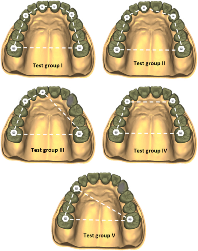 Figure 1
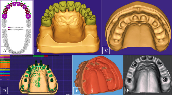 Figure 2
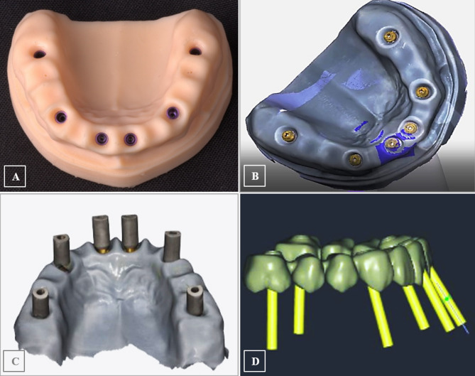 Figure 3
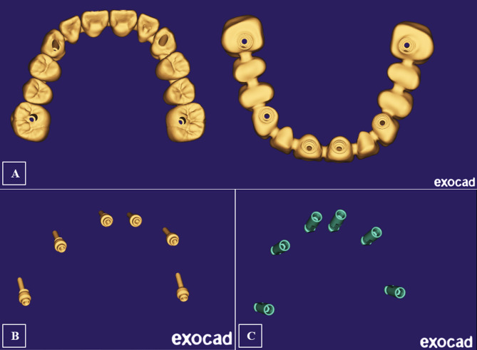 Figure 4
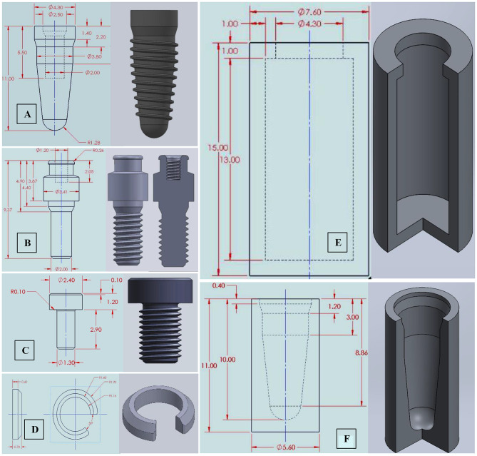 Figure 5
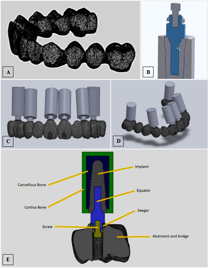 Figure 6
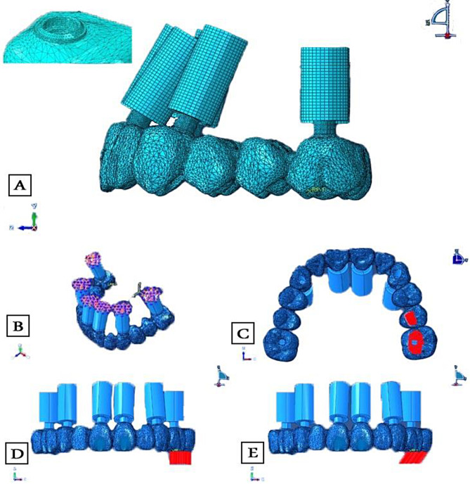 Figure 7
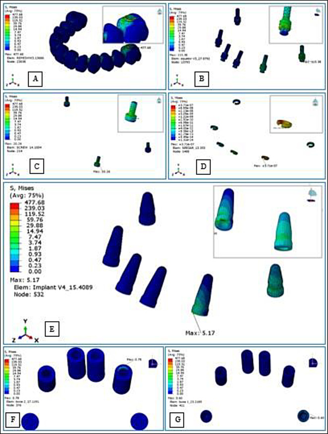 Figure 8
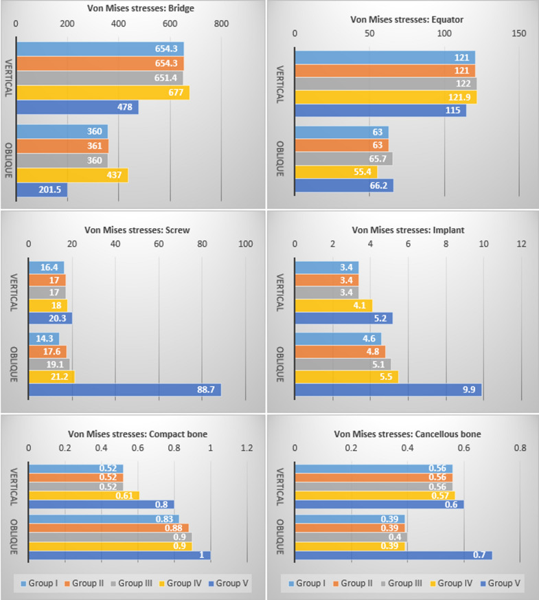 Figure 9
- —EUN Egyptian Universities Network
Peer Reviews
No public reviews on file for this paper yet. If you reviewed it on a platform where reviews are public (OpenReview, ICLR, NeurIPS, ICML), you can paste yours below so the community can read it here.
Videos
No videos yet. Explain this paper in a talk, walkthrough, or lecture? Add one.
Taxonomy
TopicsDental Implant Techniques and Outcomes · Dental Radiography and Imaging · Orthopaedic implants and arthroplasty
Introduction
The reconstruction of the edentulous maxilla with dental implants is a complicated and multifaceted treatment. The maxilla’s anatomical restrictions, high esthetic demand, and atypical resorption pattern present a significant portion of the reconstruction’s difficulty that impacts the ideal implant placement and makes it difficult to design a traditional screw-retained prosthesis; thus, using intermediate abutments is highly advised [1–4]. Thus far, multi-unit abutments (MUA) are the most widely used to convert the implant connections in full arch rehabilitations. They are designed with a range of angle corrections and an external conical connection that allows a passive prosthesis fit. The principal limitations however are related to their wide diameter and weak tiny secondary screw [4, 5]. Recently, the novel low-profile and narrow OT-Equator abutments were proposed as an alternative to the MUA for screw-retained restorations delivered at the abutment level, constituting the central core of the prosthetic project “OT-Bridge” [6, 7]. The OT-Equator has a unique morphology and much more robust structure than MUA’s; it does not need a through screw thus lowering the possibility of fracture, and its locking screw is 30% bigger ensuring more resistance [8, 9].
Owing to its many distinctive components, Rhein 83^®^’s OT-Bridge system was introduced as a creative way to address the shortcomings of the fixed prosthetic systems that were previously available [8]. One of its key components is the sub-equatorial “Seeger”; it is an exchangeable acetal ring housed in a cylindrical “Extragrade” abutment. The Seeger expands to follow the equator head and reverts to its initial shape when it reaches the equator base signifying a monoblock link between the extragrade abutments and the equator which could enable avoiding many unaesthetic screw holes; the clinician will be able to use the abutment in “Blind mode” without anchoring screws retaining the connection only to the seeger, this is a significant feature in the aesthetics zone when implants are not placed in an ideal prosthetic way [9].
Some of the promised benefits of the OT Bridge concept were discussed in the available literature; the biological merits, for instance, are supported by several studies that evaluated the periodontal parameters, clinical outcomes, biological and technical complications, and survival and success rates of this prosthetic project [8, 10–13]. According to Acampora et al. [10], minimal peri-implant bone loss was experienced one year after loading, in agreement with the one-abutment one-time concept [14]. The OT-Equator also provides for the platform-switching concept that aids in minimizing peri-implant bone loss. Moreover, compared to MUA, the lack of locking screws lessens bacterial growth and contamination within the implant [15].
Other advantages of the OT Bridge system supported by Tallarico et al. [9] were related to its ability to overcome high implant divergence, as the Seeger ring gives stability and passivation even with strong disparallelisms [13]. El Mashad et al. [11] also declared that the novel OT-Bridge system, with its integrated seeger, is a promising concept that solves the passivity issue of full arch implant restorations. In addition, the majority of professional CAD software offers the OT-equator as a public library, enabling the prospective planning of prosthetically-driven implant rehabilitations, making it possible to combine well-established surgical methods, like All-on-X, with innovative digital surgical-guided execution of virtual implant planning, ultimately enhancing implant positioning accuracy and immediate loading protocols [16, 17].
One of the most frequent failures and biomechanical complications in implant-supported prostheses is related to screw loosening and fracture [18, 19] The OT-Bridge seeger ring provides a secure elastic retention system of the abutment against the possibility of prosthesis unscrewing [7, 20], this “snap” retention of the extragrade abutment can as well compensate when the initial screw tightening is lost [8, 10]. Moreover, some screws can be avoided without affecting the prosthesis stability; the generic rule is that one of four screws or 25 ٪ of total screws can be avoided [8,9). In this regard, some in-vitro studies demonstrated that the OT-Bridge system could be efficiently used in all-on-four rehabilitations in the absence of one screw among four [16, 20–22]. However, the available literature hasn’t yet investigated the impact of changing the distribution of the eliminated screws on the OT-Bridge biomechanical behavior when more implants are involved in prosthesis support.
Since several variables can affect the stress patterns in the implant-prosthesis-bone complex, finite element analysis (FEA) studies are currently employed to cover significant research gaps on dental implants [23]. Different FEA studies looked into how stress shielding and bone density can affect implant/abutment design and material selection [24–27]. Other studies investigated the impact of implant locations, numbers, and angulations [28–30]. Others focused on the influence of prosthesis materials and design [31, 32]. By simulating the actual behavior of the components under specified load conditions and examining implant/prosthesis lapses relative to the distribution of tensions and deformations within them, these studies will help optimize dental implants and reduce the failure rates for implant therapy.
The potential aesthetic problems that result from labial screw emergence in full-arch prosthesis typically require removing anterior screws. Nonetheless, specific circumstances involving incorrectly angled or positioned posterior or anterior implants during complete arch rehabilitation may require a distinct shift in the allocation of abutments used without screws [9]. This highlights the importance of investigating the distribution of the screwless connections in the maxillary OT-Bridge prostheses. Thus, this FEA study aimed to evaluate the stresses induced in an All-on-six maxillary OT-Bridge prosthesis in different circumstances that vary in number and geometric distribution of the employed retaining screws. The null hypothesis was that; there would be no difference in the peak stress distribution within this prosthetic system between the study groups having different numbers or the study groups having different distributions of connecting screws.
Materials and methods
This study was conducted on a three-dimensional FE model (3D FEM) of an edentulous maxilla restored with a full arch fixed implant OT-Bridge prosthesis supported by six implants following the Carl Mesh “All-on-six” design [33]. The study compromised five test groups based on the number and geometrical distribution of the connection screws used to anchor the implant superstructure as follows; Group I: Six connection screws were applied, Group II: Five connection screws were applied with elimination of the right central screw, Group III: Four connection screws were applied, entrusting the connection only to the seeger for the right central and canine, Group IV: Four connection screws were applied, entrusting the connection only to the seeger for the two central incisors. Group V: Three connection screws were applied trusting the connection only to the seeger for the two central incisors and the right canine (Fig. 1).
Fig. 1. Schematic illustration of the five study groups
Designing model geometry and reverse engineering
A cone beam computed tomographic (CBCT) scan of an edentulous maxilla that could be rehabilitated with six implants was obtained from the oral radiology department and employed to design the 3D numerical model. The acquired scan data were introduced into the Exocad model-creator module (Exocad GmbH, Hessen, Germany) to create a surface model without noise. A virtual teeth setup was established, and implant position detection was based on six scan bodies (Vitronex Elite Implant System, FLOTECNO SRL, Italy) aligned virtually in six key teeth positions over the model crest (Fig. 2A-D). The matching digital implant analogs from the CAD library were selected and their positions were adjusted within the maxillary model confines as follows; the two anterior implants were located at the central incisors’ positions with 30° angulation, two implants were located at canines’ regions with 16° angulation, and the posterior two implants were situated at the first molars’ region in an upright orientation (Fig. 2E). The digital analogs holes were automatically created in the DIM design based on the final positions and orientation of the analogs, and the soft tissue emergence profile borders were finally defined to complete the model design (Fig. 2F).
Based on the generated CAM file, the stereolithographic cast was 3D printed (AccuFab-D1s 3D printer, SHINING 3D, China), then six digital analogs were installed in the printed cast (Vitronex, Elite Implant System, Italy) (Fig. 3A). The OT-equator abutments were tightened over the implant analogs (OT Equator abutment, Rhin83, Bologna, Italy), the scan bodies for equator abutments were mounted (Scan body, Rhin83, Bologna, Italy), and the model was scanned using an intraoral scanner (MEDIT I700 intraoral scanner, Seoul, Korea) (Fig. 3B&C). Using the virtual extragrade abutments in the Rhein83 digital library, a single framework was designed as an anatomic setup based on the equator positions, guided by a virtual prosthetic tooth arrangement (twelve teeth from central incisors to first molars bilaterally) (Fig. 3D). The abutment connection of the bridge was modelled, and the seeger rings were simulated inside the extragrade abutments as specified by the manufacturer. A (Seeger-Bridge-Direct) connection from the library was selected to deal with the bridge and abutments as one unit.
All CAD models were converted to Standard Tessellation Language (STL) files. Three STL files were prepared: The bridge with extragrade abutments, the implant analogues, and the OT-equators (Fig. 4A-C). The native STL files were re-meshed to reduce their size while maintaining quality.
Fig. 2. Geometry designing; virtual teeth arrangement over the modeled maxillary arch (A,** B**), to define the key implant positions on the model crest (C), for positioning the scan bodies (D), and implant position detection based on the scan body alignments, (E) yielding the final digital implant model design (F)
Fig. 3. The 3D printed DIM with digital analogs in position (A), and model scanning after installation of equator abutment (B&C), to generate the design of a twelve-unit OT-bridge based on the replicated implants/equator positions (D)
Fig. 4. The prepared STL files for the bridge with extragrade abutments (A), the orientation of the OT-equators (B), and implant analogs (C)
Modeling using solidworks
Due to the bridge complexity, the 3D information obtained from the STL file was directly used for FE modeling. For implants, screws, and equators, modeling was guided by the corresponding CAD coordinates to replicate their spatial 3D orientation but was accomplished according to accurate dimensions of designs collected from the manufacturer; implants with an internal hex connection and a diameter of 4.3 mm were drawn; measuring 11 mm in length for the four anterior implants and 9 mm for the two posterior implants (CAMLOG Root-Line, Germany), the OT equator missing information was acquired (Rhin83, Bologna, Italy), the equator screw was drawn to be 2 mm in diameter and the prosthetic screw to be 1.3 mm, the seeger was drawn to fill the space between the equator and the bridge intaglio, and the peri-implant bone was schematized as surrounding cylinders; [25, 26, 34] the cortical bone was drawn as 1 mm thick, and the spongy bone was drawn as an internal structure [35]. Finally, all 2D-sketches were converted into 3D-components (Fig. 5A-G).
Fig. 5. Components’ 2D sketches and their 3D modeling for; implants (A), equator abutments (B), prosthetic screws (C), Seeger rings (D), and cortical and cancellous bone cylinders (E&F)
The prepared files were converted into a solid body. The assembly module of SolidWorks software (Version 2024, Dassult System, Solidworks Corporation) was used to define the geometry of the assembly; the study components were created as repeated units’ sub-assembly files each composed of an implant surrounded by a cylindrical volume of cortical and cancellous bone with an equator mounted over the implant. The six subassembly files were gathered with the bridge STEP file (standard for the exchange of product data) producing the final assembly file of the bridge supported with the six bony-encompassed implants and connected to them via the OT- equators using prosthetic screws along with six seeger rings allied inside the bridge (Fig. 6A-E).
Fig. 6. Modeling using SolidWorks; the bridge’s solid body (A), a cross-sectional diagram for the repeated-unit subassembly file (B), frontal and side views displaying the orientation of the six subassembly files gathered with the bridge STEP file producing the final assembly file (C,** D**), and schematic illustration in cross-section for the assembled components (E)
Meshing and element type
All files were exported as Parasolid files to be meshed and analyzed in ABAQUS 2024 (Dassault Systèmes Americas Corp., 1301 Atwood Avenue, Suite 101 W, Johnston, RI 02919, USA). The “h-refinement” method was used to perform a mesh convergence; the mesh was refined by increasing the element number from a coarse mesh to a finer mesh until the results converged. The convergence was evaluated by monitoring the changes in the maximum vMS relative to the number of elements. The convergence was met when the relative error in the maximum vMS between two consecutive mesh refinements was below a specified tolerance value (2% in this study) to provide a good balance between accuracy and computational efficiency [26]. Linear hexahedral elements were used for mesh generation, except for meshing of the bridge, modified quadratic tetrahedral elements were adjusted with a 0.5 mm element size, with additional refining to 0.25 mm at equator-bridge connection regions [36] (Fig. 7A). The total element number for the created FEM was 721,137 while the total number of nodes was 1,020,282. The number of nodes and elements of each component are listed in Table 1. The framework, OT equators, screws and implants were simulated to be made of titanium, and the seeger was considered an elastic rubber material [21, 25, 31, 36, 37] All materials were considered isotropic, homogeneous, and linearly elastic. Two essential material parameters were required: elastic (Young’s) modulus (E) and Poisson’s ratio (ν) (Table 2).
Fig. 7. Meshing and analysis using ABAQUS; mesh generation for the components and mesh refining at the connection area (A), applying constraints (B), and the area of load application on the experimental model (C), in vertical (D), and oblique directions (E)
Table 1. Number of elements and nodes of each componentComponentElement typeElementsNodesReplicatestotal elementstotal nodesAverage aspect ratioWorst aspect ratioElement size (mm)1.Compact BoneC3D8R7401,42142,9605,6841.692.230.752.Compact Bone(posterior)C3D8R1,2721,95322,5443,9061.551.990.653.Cancellous BoneC3D8R4,0405,265416,16021,0601.496.090.404.Cancellous Bone (posterior)C3D8R2,6243,51125,2487,0221.604.870.405.Implant (11 mm)C3D8R5,8807,031423,52028,1241.744.090.276.Implant (9 mm)C3D8R8961,20821,7922,4162.074.010.457.EquatorC3D8R5,8226,814634,93240,8841.844.140.228.ScrewC3D8R4,0324,862624,19229,1721.543.540.149.SeegrC3D8R1,0701,65066,4209,9001.663.510.1410.BridgeC3D10M603,369872,1141603,369872,1141.6812.070.5/0.25 near implantTotal elements inside the model721,137Total nodes inside the model1,020,282C3D8R: linear hexahedral elementsC3D10M: Modified quadratic tetrahedral elements
Table 2. Defined properties of the materials usedElementMaterialPoisson’s ratio(ν)Modulus of elasticity (MPa)Density (tonne/mm3)Cancellous boneBone0.301370 (12)4.66E-10 (145)Compact boneBone0.3013,700 (12)1.45E-9 (145)Seegerelastic0.352600 (134)1.39E-09 (134)ImplantEquatorsFrameworkScrewsTitanium (TiAl6V4)0.35110,000 (173)4.62E-09Ti indicates; titanium, Al; aluminum, V; vanadiumE: Elastic (Young’s) modulus
Constraints, interface and boundary conditions
The models were subjected to a rigid fixation restriction in the upper maxilla (Fig. 7B). Before the system equations were ready for solution, they were modified to account for the boundary conditions. All components were constructed with 100% contact along all surface interfaces with no gaps. Perfect integration between bone and implant was considered; this was achieved using a tied contact, so there is no motion between the two structures under applied loading, as recommended by relevant literature [21–23, 31]. The interphase between cortical and cancellous bone layers was considered well-bonded. A friction coefficient was considered 0.3 for the implant/equator and equator/abutment interphases, and 0.35 for the Seeger/equator and Seeger/abutment interphases [21]. Finally, for contact between prosthetic screws and equators, a friction coefficient of 0.5 was defined [34] (Table 3).
Table 3. Frictional coefficient and contact type of the componentsConnectionContact typeFriction coefficientCancellous bone / Compact boneBonded--Compact-Cancellous bone / ImplantBonded--Prosthetic screw / EquatorFrictional0.5Implant / EquatorFrictional0.3Equator / SeegerFrictional0.35Equator / AbutmentFrictional0.3Seeger / AbutmentFrictional0.35Abutment / BridgeBonded--
Loading and running the analysis
Load conditions were applied unilaterally (on the positive Y axis) over an area that included the central fossae of the second premolar and the first molar, where most of the masticatory load is applied in centric occlusion, and it was applied to an area rather than a single point to avoid stress concentration [38]. To mimic the ontogeny of average bite force in humans when rehabilitated by full-arch implant prostheses, the analysis was run under an axial load of 250 N [26, 35, 39], and as oblique forces more accurately reflect occlusal stresses, an oblique load of 150 N was applied to the same sites at 30° inclination in a palato-buccal direction [31, 34] (Fig. 7C-E). Dynamic analysis was accomplished, and the maximum generated vMS in the; bridge, prosthetic screws, seeger rings, equators, fixtures, cortical, and cancellous bone were calculated (Fig. 8A-G).
Fig. 8. Assessment of von Mises Stresses in; the bridge (A), seeger rings (B), screws (C), equators (D), implants (E), compact bone (F), and cancellous bone (G)
Statistical analysis
The vMS values were recorded and tabulated for the five study groups under the two load conditions (Table 4). Due to the nature of FEA, there was no need to calculate the sample size because it is a computer simulation where all co-founders can be controlled. Upon repeating the test many times, the same result will be achieved, thus, it was not feasible to conduct a comprehensive statistical analysis for the resultant stresses [40].
Table 4vMS values (MPa) and peak-stress concentration areas in the components under vertical and oblique loadsGroup IGroup IIGroup IIIGroup IVGroup VverticalObliqueverticalobliqueVerticalobliqueverticalobliqueverticalobliqueBridge654.3left molar360left molar654.3left molar361left molar651.4Left molar360left molar677left molar437left molar478left molar201.5left molarScrew16.4left canine14.3left canine17Left canine17.6left canine17Left canine19.1left canine18Left canine21.2left canine20.3Left canine88.7Left canineSeeger4 ^e-7^Left canine2 ^e-9^left canine2 ^e-8^Left central1 ^e-8^left canine8 ^e-8^Left central2 ^e-8^Left central1 ^e-4^Right canine5 ^e-9^Right canine1 ^e-9^Left canine3 ^e-6^Right centralEquator121Left molar63Left molar121Left molar63Left molar122Left molar65.7Left molar121.9Left molar55.4Left molar115Left molar66.2Left molarImplant3.4Left canine4.6Left molar3.4Left canine4.8Left molar3.4Left canine5.1Left central4.1Left canine5.5Left canine5.2Left canine9.9Left molarCompact bone0.52Left canine0.83Left canine0.52Left canine0.88Left molar0.52Left canine0.9Left molar0.61Left canine0.9Left molar0.8Left canine1.0Left molarCancellous bone0.56Left molar0.39Left molar0.56Left molar0.39Left molar0.56Left molar0.4Left molar0.57Left molar0.39Left molar0.6Left molar0.7Left molar
Results
In all groups, the highest stress values were recorded for the bridge followed by the equator abutments, screws, implants, and bony segments respectively, and the lowest negligible stress values were recorded for the seeger. All groups demonstrated similar stress distribution patterns, marked by gradual stress dispersion from the load-bearing to the non-load-bearing sides, except for group V, which exhibited more concentrated stresses on the load-bearing side. The peak of all component stresses was mostly concentrated at the first molar region where the load was applied, however, the stresses were greatest at the left canine region for the screws under both loading conditions, and for the implants and the compact bone under vertical loading (Table 4). Due to the limited sample size of one for each group, descriptive statistics were retrieved from the analyzed FEMs to compare the vMS values for each component between the groups and between vertical and oblique loading conditions (Fig. 9).
Fig. 9. Descriptive charts for comparison of von Mises Stress between the groups: bridge, equators, screws, implants, compact, and cancellous bone under vertical and oblique load
Intergroup comparisons of induced stresses in the different components
For the bridge, the highest stress values under both load conditions were found in group IV, while the lowest values were in group V. For the OT equator, the highest value under axial load was in group III, while the lowest was in group V. On the other hand, the highest value under oblique load was recorded for group V, while the lowest was recorded for group IV. With the elimination of more than one-third of the screws in group V, the stresses on the screws, implants, and the two bone segments significantly increased. Under both load conditions, the most stressed screws were found in group V and group I screws were the least stressed (the stresses on the screws were 4 times higher under oblique load). The highest stress values recorded for implants and peri-implant bone were also in group V, while the lowest was in group I (implants and cancellous bone showed nearly a twofold increase in stresses under oblique load). Regarding the geometric distribution of the eliminated screws, the results displayed that the bilateral elimination of the two anterior screws in group IV compared to the unilateral screw elimination in group III increased the stresses on the bridge by 1.04 and 1.21 times, on the screws by 1.05 and 1.1 times, and on the implants by 1.2 and 1.07 times under vertical and oblique loads respectively (Fig. 9).
Intragroup comparisons of induced stresses under vertical and oblique loading
von Mises Stress values recorded for the bridge and the equator were higher under vertical load than under oblique load in all groups; the peak stress at the equators under vertical load was nearly twice that recorded under oblique load. However, the peak stresses for screws were slightly higher under oblique load than that recorded under vertical load particularly in group V; there was a massive increase in stresses under oblique load compared to those recorded under vertical load. However, in group I, the stresses were higher under vertical load. The peak stresses for the implants and cortical bone under vertical load were lower than those recorded under oblique load. For the cancellous bone, only in group V the stresses induced under oblique load were greater than vertical load, in contrast to the trend observed in all other groups, where stresses induced under vertical load were greater than under oblique load (Fig. 9).
Discussion
In the present study, the null hypothesis was rejected as the results showed that the peak stresses induced in the implant-retained OT-Bridge were affected by the number of eliminated screws, as well as their geometric distribution, where the elimination of more than two screws out of six generated different stress patterns compared to other designs, and also bilateral elimination of two anterior screws generated higher stresses than their unilateral elimination.
Some studies demonstrated the reliability of the OT-Bridge in all-on-four mandibular rehabilitation when one of the screws is absent [16, 21, 22]. However, in the current study, the five clinical situations were simulated for a maxillary model restored with six implants to reflect the esthetic demand for maxillary rehabilitations [41] because no studies provided precise guidelines for screwless abutment use when more than four implants are used to support a maxillary prosthesis. Long-span situations also exhibit increased stresses and reduced survival prediction than short-span cases, thus, the prosthetic structure is more critical for preserving the system stability [42, 43].
The results of our study have been compared for validity with other experimental studies in the literature [16, 21, 22, 31]; one was a FEA study similar to our work, conducted to investigate the mechanical behavior of the OT-Bridge in a mandibular model with four implants. However, in this study [21], the prosthesis was subjected to 800 N load for test groups (1&2) and 700 N load for test groups (3&4) divided into the two molar regions, although these force levels might not hold in reality, the authors used a failure criterion where simulations were terminated upon reaching a specific displacement values, and comparisons were made based on the equivalent load that caused failure for each group. In contrast to our study, using a constant, realistic load across all groups allows the portrayal of a real clinical state and evaluation of the structural performance under standardized loading conditions.
The vMS criterion is widely used to assess stress in metals and other ductile materials [32, 37]. The highest vMS values were recorded for the bridge followed by the equator abutments, screws, implants, and bony segments respectively. These findings corroborate with other studies [21, 31, 44, 45] and indicate favorable biomechanical behavior of the OT-bridge prosthesis in all groups regardless of the number of eliminated screws, as in the same context the forces are absorbed by the rigid superstructure transmitting lower vMS in implants and bone [46].
The stress values observed in all test groups were within the physiological limits of bone tissue as according to ultimate bone strength, overloading in cortical bone occurs when the σ min exceeds 170 to 190 MPa and, the σ max exceeds 100 to 130 MPa, while overloading in trabecular bone happens when either σ min or σ max exceeds 5 MPa [47, 48]. The reduced bone stresses observed in the current study can be correlated to the OT-equator’s unique design that can concentrate tension over the retainer’s head, allowing minor stresses to distribute across the fixture and peri-implant bone [6]. Furthermore, a portion of the stresses could be dissipated by the seeger ring elastic action [16, 21, 22].
Although the highest stresses were recorded in the prosthetic superstructure, all stress values recorded for all groups were within the tensile strength limit of titanium (860 to 965 MPa) [49]. On the other hand, the lowest stress values were recorded for the seeger, which could be explained by the fact that it is made of acetal resin and has a distinctive open-ring design. Acetal resins are considered bridge-building polymers between plastic and metal; they provide the durability of metal and the comfort and flexibility of plastics, and they are characterized by having a strong elastic memory [50]. In a state of tension, the seeger rings can distort themselves, dissipating the stresses due to their strong elastic memory and incomplete circumference [16].
It is evident from the current study results that groups; I, II, and III had nearly identical peak stress distribution patterns in the system; they demonstrated a more balanced biomechanical performance with less stress concentration on the implant and bone compared to groups IV and V. This highlights that using five or even four prosthetic screws instead of six still seems to be safe and predictable, certifying the seeger ring’s ability to interlock the prosthesis and counterbalance the imposed forces [22]. These findings are consistent with the results of Cervino’s and Milone’s studies [16, 21].
Based on the analysis of the current study findings, removing three screws out of six in group V dramatically changed the force distribution pattern. Although the highest stresses recorded for the bridge and equator abutments were in groups III and IV rather than group V as was expected when a greater portion of the framework becomes a cantilever without screws [46], the stresses on the screws, the implants, and the two bony segments showed the expected ascending increase with the elimination of more screws from group I to group V which align with other study findings where removing connection screws increased stress distribution to bone [21]. In group V, the reduced stresses in the bridge under both load conditions and in equators under vertical load were accompanied by significantly higher stress concentrations in the screws, implants, and compact and cancellous bone, indicating less favorable biomechanical behavior, greater risk of clinical complications such as; screw loosening and loss of osseointegration in an equivalent real-life scenario if half of the screws were discarded.
Regarding the effect of the geometric distribution represented by the different positions of the two eliminated screws in groups III and IV, the results displayed that the bilateral elimination of the two anterior screws in group IV compared to the unilateral screw elimination in group III increased the stresses on bridge, screws, implants, and bone, this validates the speculation that the prosthesis could behave differently when the geometric distribution of the removed screws changes. Compared to group III, group IV recorded higher vMS in the bridge, but lower stress concentration in equator abutments, the quadrilateral spread-out of the applied screws that tightly connect the superstructure to the implants could explain higher force absorption by the bridge [51, 52]. Group IV simultaneously showed higher stress levels in the bone, implants, and screws thus demonstrating less advantageous biomechanical behavior; according to Benzing’s study [51], this means increased prosthesis deformation near the load application.
A FEA study conducted on six implant-supported frameworks with different cantilever lengths demonstrated that when the framework acts as a cantilever, the longer the lever arm, the higher the stresses [46]. Similarly, we can interpret the findings of the current study; the disparity between groups III and IV in the surface area covered by the connecting screws versus the cantilevered area retained only by the seeger could be the reason behind the redistribution of the stresses although same screw count was applied; the increased frontal cantilever length in group IV relative to the anchored area seems to be a logical interpretation [33, 46, 51].
Regarding peak stress concentration patterns, all five study groups showed similar results, the first molar region was primarily where the peak of each component stress was located regardless of the position of the eliminated screws, this finding was consistent with several studies that demonstrated the highest stress concentration points coincided with the location of the load application [21, 31, 32, 52]. However, the stresses were greatest at the left canine screws under both loading conditions, and at the left canine implants and compact bone under vertical loading. These findings could be related to the stress absorption by the bridge and abutments in the premolar-molar region, so stresses are transmitted more to infrastructure as we get farther from the location of the load application, and reach its peak at the nearest canine due to its location at the corner of the arch [53]. This might signify how crucial it is to carefully choose the occlusal scheme relative to the locations of the removed screws in the OT-bridge prosthesis [54]. On the positive side, the screws in every group had stress values that were less than titanium’s tensile and compressive strengths, preventing an instantaneous fracture [55].
The peak stress distribution within the seeger rings varied between the groups; in groups I and II, the highest seeger stresses were recorded at the left canine region; however, stress peaks were shifted to the left central position in group III and to the right canine position in group IV. In group V, the greatest seeger stresses under vertical load were at the left canine position, but under oblique load at the right central incisor. A recent investigation that assessed the forces generated at the seeger level during loading demonstrated comparable findings; they concluded that the seeger rings closer to the screwless abutment and load application, and seeger rings of screwless connections were the most supposed to deform because of the intensity of force generated on the XY plane and the Z-axis [22].
Providing the current literature with these in vitro testing outcomes would help clinicians comprehend the clinical implications of determining the most appropriate prosthetic design when rehabilitating their patients using the OT-Bridge system. However, the study’s findings may be influenced by the additional in vivo biological and clinical complexities, thus, they should be regarded cautiously. Another limitation of this study is related to the employed static loading conditions, which might underestimate the loading effect in the case of dental implants and fail to account for the potential reasons for fatigue failures or fractures [23, 43]. Furthermore, completing the simulation typically requires making certain assumptions that are standard in FEA studies but might not hold in the real situation [56]. However, due to the comparative nature of the current study, such assumptions wouldn’t interfere with the aim because they exist in all the groups.
Considering these points, future FEA studies simulating the dynamic nature of forces that occur during chewing and the other implant-supported treatment alternatives for maxilla and mandible that include; different implant numbers, different geometric distribution of eliminated screws, different framework materials and designs, and different occlusal designs are needed to verify the findings of this study. Also, clinical trials with long-term follow-up are necessary to confirm the relevance of these findings in clinical cases.
Conclusions
Within the limitations of the current study, the following could be concluded:
- The OT-Bridge is considered a biomechanically efficient prosthetic system even in the absence of one-third of the anchoring screws in all-on-six prostheses. Nevertheless, eliminating more than two screws out of six increases the stresses generated in the prosthetic components and the peri-implant environment.
- The number of eliminated screws, as well as their geometric distribution, influence the stress pattern in the OT-Bridge prostheses; for all-on-six prostheses, unilateral rather than bilateral elimination of two anterior screws results in better biomechanical behavior.