A Self-Powered Density-Based Device for Automatic Mixed-Oil Cutting in Field Pipelines
Zhen Zhang, Yonggang Zuo, Huishu Liu, Biao He

TL;DR
A self-powered device detects oil mixtures in pipelines using gravity, enabling automatic separation without external power.
Contribution
A novel self-powered, gravity-based device for automatic mixed-oil interface detection and cutting in remote pipelines is introduced.
Findings
The device achieves a 10 kg/m³ resolution for density changes using a float-based mechanism.
Switching times range from 61 to 395 seconds for density differences between 760 and 835 kg/m³.
The design supports blending ratios of 20–90% and includes a vent to mitigate gas effects.
Abstract
Efficient oil transportation in field-deployed mobile pipelines is critical, but mixed-oil zones at interfaces reduce quality and increase waste, necessitating effective interface detection and cutting. Existing online densitometers, such as vibrating tube or high-accuracy magnetic suspension types, typically require external power, limiting their use in remote or emergency/temporary field operations. A self-powered device is presented that leverages gravitational force variations acting on a float to detect density changes and trigger automatic cutting. Validated with gasoline, diesel, kerosene, and water, it achieves a 10 kg/m3 resolution, deemed sufficient for functional batch separation in its target application, with switching times of 61–395 s for density differences (760–835 kg/m3). It supports 20–90% blending ratios, with a vent mitigating gas effects. The modular, robust,…
Genes, proteins, chemicals, diseases, species, mutations and cell lines named across the full text — each resolved to its canonical identifier and authoritative record.
Click any figure to enlarge with its caption.
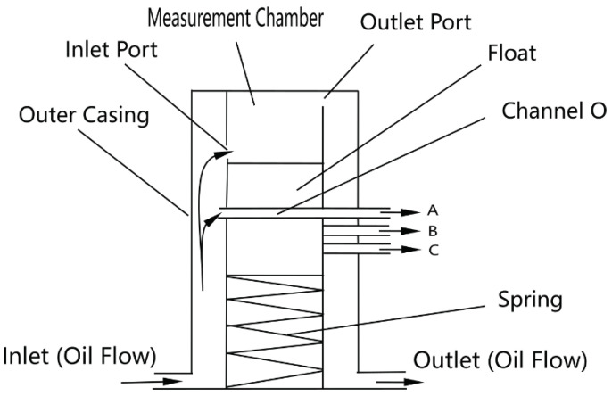 Figure 1
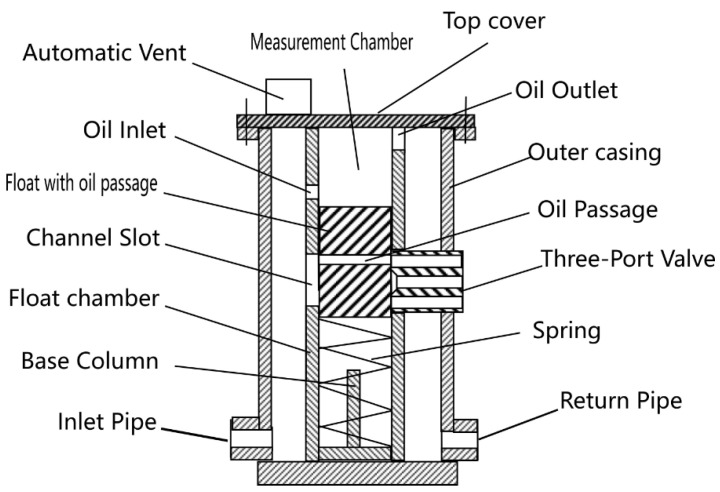 Figure 2
 Figure 3
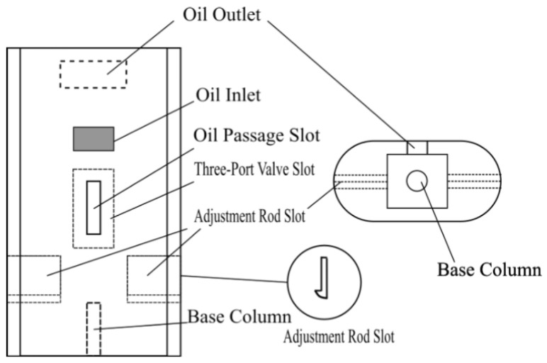 Figure 4
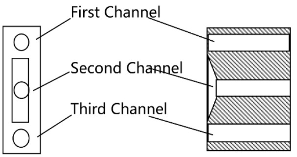 Figure 5
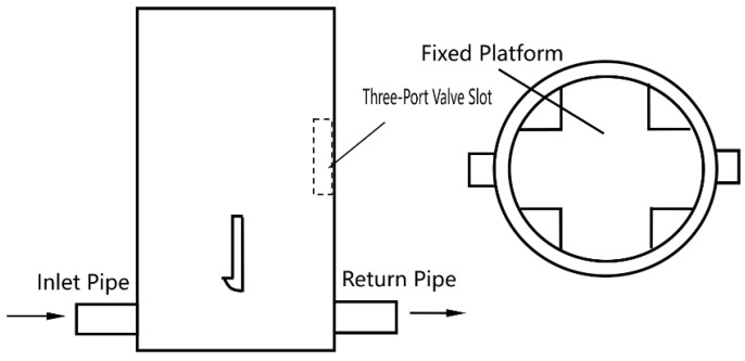 Figure 6
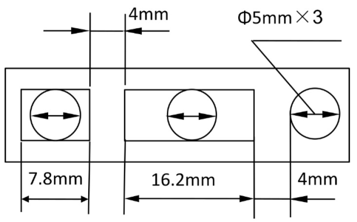 Figure 7
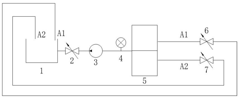 Figure 8
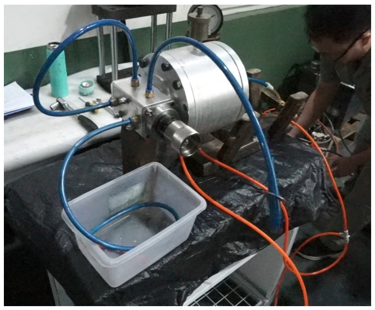 Figure 9
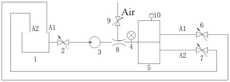 Figure 10
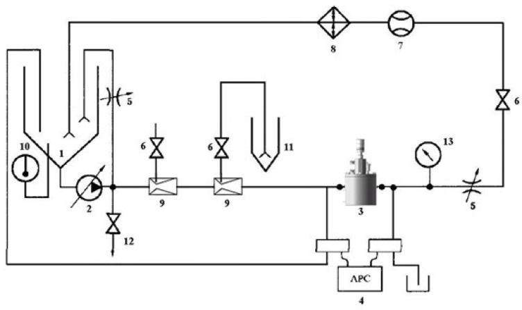 Figure 11
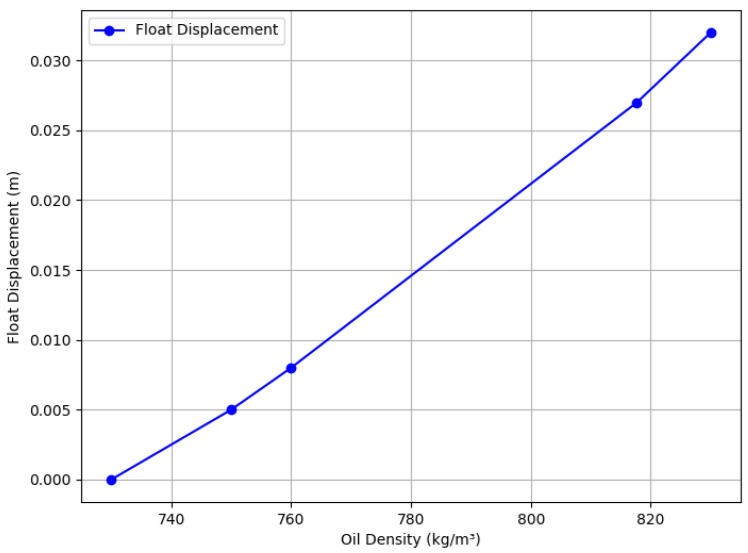 Figure 12
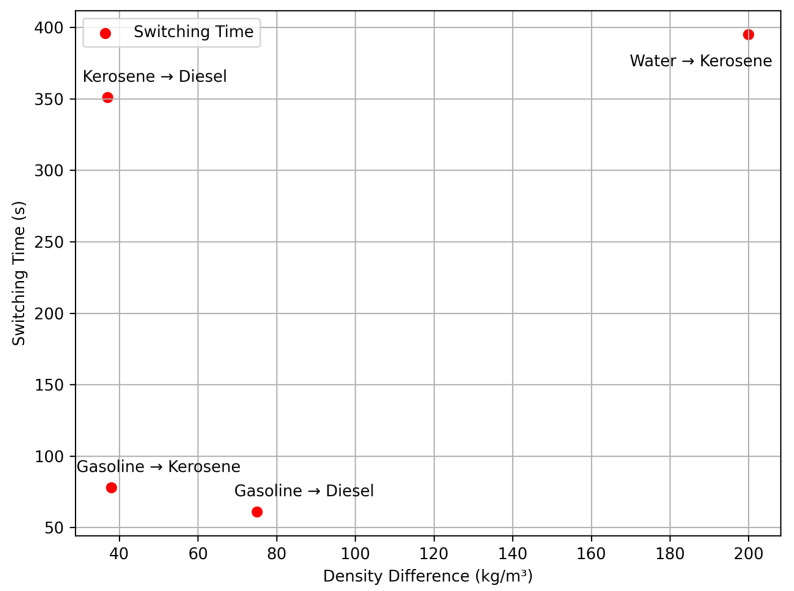 Figure 13
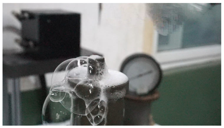 Figure 14
- —National Natural Science Foundation of China
Peer Reviews
No public reviews on file for this paper yet. If you reviewed it on a platform where reviews are public (OpenReview, ICLR, NeurIPS, ICML), you can paste yours below so the community can read it here.
Videos
No videos yet. Explain this paper in a talk, walkthrough, or lecture? Add one.
Taxonomy
TopicsNon-Destructive Testing Techniques · Oil and Gas Production Techniques · Welding Techniques and Residual Stresses
1. Introduction
The efficient transportation of oil via pipelines is critical for meeting global energy demands [1]. In field-deployed mobile pipelines, used in emergency scenarios (e.g., disaster response, military logistics) or temporary operations (e.g., remote oilfields) [2,3] sequential transportation—where different oil products are conveyed consecutively within the same pipeline—maximizes operational efficiency [1,4]. However, this method results in a mixed-oil zone at the interface between products, which can degrade product quality, increase waste, and pose safety concerns [5]. Effective mixed-oil detection and cutting is essential to minimize product loss and environmental impact, supporting sustainable oil transportation [6].
Current online density measurement methods, such as precise vibrating tube [7] or radiation-based densitometers [8], are widely used in permanent installations. Highly accurate density measurements are also possible with specialized equipment like magnetic suspension balances [8,9]. However, these instruments often require significant external power, stable laboratory conditions, or complex infrastructure, making them less practical for remote, rapidly deployed mobile settings where power is unreliable and robustness is paramount [7,8]. While advanced interface detection sensors are being developed [10] they often face similar power and portability constraints in mobile contexts.
Beyond operational efficiency, managing mixed-oil formation aligns with global sustainability goals by reducing contamination risks [11,12]. Various other density measurement techniques (e.g., ultrasonic [13,14], differential pressure [15]) exist, but typically require external power and signal processing. Traditional hydrometers, while simple, are inherently unsuitable for automated, inline monitoring in dynamic pipeline flows due to their operating principle requiring manual reading or static conditions. The trend towards self-powered sensors, often based on Triboelectric Nanogenerators (TENGs) [16,17,18], is promising for remote applications, but these currently focus on parameters like fluid velocity or energy harvesting, lacking the specific precision or mechanism required for density-based mixed-oil cutting.
This paper presents a novel self-powered, density-based automatic cutting device designed specifically for field-deployed mobile pipelines. It prioritizes robustness, simplicity, and power independence over the ultra-high precision demanded in permanent pipeline systems. The device integrates density sensing (via float displacement driven by gravitational/buoyancy forces) with mechanical actuation to enable automatic mixed-oil cutting, offering a practical solution for challenging field environments, as illustrated in the schematic design (Figure 1).
2. Materials and Methods
2.1. Device Composition
The device comprises a top cover, outer casing, float with oil passage, float chamber, spring, three-port valve, and automatic vent, as depicted in Figure 2.
2.2. Key Component Design
Top Cover: Includes an automatic vent to prevent gas interference, bolted for maintenance.Float Chamber: Contains the float, spring, and base column, with oil inlet/outlet and adjustment rod slots.Three-Port Valve: Controls cutting signals with channels for gasoline, mixed oil, and diesel.Outer Casing: Houses inlet/return pipes and secures the float chamber.
2.3. Modular Design
The float and float chamber are modular, allowing interchangeability to accommodate various fluid density ranges (e.g., gasoline, diesel, kerosene, or heavier oils), enhancing versatility. This design enables adaptation to different fluids by swapping components, as shown in Figure 3 and Figure 4, minimizing the need for structural redesign.
2.4. Detailed Design
Detailed schematics of individual components are provided for clarity: the float (Figure 3), float chamber (Figure 4), three-port valve (Figure 5), and outer casing (Figure 6).
2.5. Material Selection
The float is constructed from stainless steel (316L, Huaxiao Metal, Shanghai, China), offering high corrosion resistance to oil and environmental exposure, with a pitting resistance equivalent number (PREN) > 25, ensuring durability in harsh field conditions. The spring is made from a nickel-chromium alloy (Inconel X-750, HWZ, Wuxi, China), selected for its fatigue life (> cycles) and stability under repeated compression. The outer casing uses an aluminum alloy (6061-T6, Xingfa Aluminium, Foshan, China) with an anodized coating to resist corrosion while maintaining lightweight portability (density 2.7 g/ ), critical for mobile pipelines, as illustrated in Figure 2, Figure 3, Figure 4, Figure 5 and Figure 6.
2.6. Working Principle
The device aims to automatically detect and cut the mixed-oil interface during sequential oil transportation in field mobile pipelines. It employs a purely mechanical design driven by gravitational force variations acting on a float, ensuring self-powered operation without external energy input. The core function is to monitor oil density continuously in dynamic flow conditions and, based on pre-set thresholds corresponding to float displacement, output control signals to switch valves, diverting oil products to separate lines. The device requires continuous flow to operates, as it relies on fluid interaction with the float, and is not designed for static conditions, as shown in Figure 1.
The device operates on buoyancy changes caused by oil density variations. Density changes affect the weight of oil in a measurement chamber, compressing a spring per Hooke’s Law, which indirectly measures density through float displacement. Figure 1 illustrates the working principle: oil enters through an inlet pipe, with a portion flowing through channel O to a cutting device, while the rest enters the measurement chamber. As mixed oil increases density, the float moves downward, aligning channel O with different pipes (A, B, C) to signal valve switches for gasoline, mixed oil, or diesel. The dimensions are shown in Figure 7.
2.7. Experimental Setup
Experiments validated the device using a test bench (Figure 8 and Figure 9), assessing density detection, switching times, gas effects (Figure 10), and mixed-oil cutting (Figure 11). Test media included gasoline (760 kg/ ), diesel (835 kg/ ), kerosene (798 kg/ ), and water (998 kg/ ).
3. Results
Building on the design, this section presents theoretical and experimental results, with performance summarized in Table 1, Table 2, Table 3, Table 4, Table 5 and Table 6 and visualized in Figure 12, Figure 13 and Figure 14.
3.1. Relationship Between Oil Density and Float Position
Assuming gasoline (730 kg/ ) followed by diesel (830 kg/ ), with a measurement chamber area of 0.01 , initial liquid level of 0.1 m, and maximum of 0.132 m, the spring compression changes by 0.032 m. The float weight is 1 N. Forces are calculated as:
The spring constant , with initial compression of 0.0728 m. The relationship between density ( ) and float displacement (x) is:
At 750 kg/ , the gasoline:diesel ratio is 8:2; at 817.7 kg/ , it is 1.23:8.77. Results are visualized in Figure 12.
3.2. Density-Controlled Pilot Valve On-Off Test
A test bench (Figure 8) validated density identification using media listed in Table 2. Results (Table 3) show a resolution of 10 kg/ , with A1 open when density is below the set point and A2 open when above. The physical setup is shown in Figure 9.
3.3. Two Test Media Test
Switching times between media (Table 4) confirm automatic cut-off, with times related to density differences, visualized in Figure 13.
3.4. Gas Effect
The automatic vent effectively removes gas, maintaining accuracy, as shown in Table 5 and Figure 10, Figure 11, Figure 12, Figure 13 and Figure 14. Over prolonged use, residual gas accumulation could slightly affect float responsiveness, but the vent design minimizes this risk, as evidenced by bubble release in Figure 14.
3.5. Mixed-Oil Experiment
Simulating field conditions in mobile pipelines, experiments used gasoline (730 kg/ ) and diesel (830 kg/ ), with the setup shown in Figure 11. At a threshold of 750 kg/ (80% gasoline, 20% diesel), A1 closes and A2 opens when diesel reaches 20%, achieving automatic cutting. At 817 kg/ (10% gasoline, 90% diesel), similar results occur. These thresholds were selected based on typical operational ranges for mobile pipelines in emergency scenarios, where broader blending ratios (20–90%) are acceptable to prioritize rapid deployment.
4. Discussion
The experimental results demonstrate that the proposed self-powered device measures fluid density with a resolution of 10 kg/ , enabling functional detection and cutting of mixed-oil interfaces in field-deployed mobile pipelines, as validated by Table 2, Table 3 and Table 4 and Figure 8, Figure 9, Figure 10, Figure 11, Figure 12, Figure 13 and Figure 14. The purely mechanical design translates density variations into valve actuation via float displacement, ensuring robustness and self-powered operation for field applications.
4.1. Operational Considerations
Compared to the high standards required for permanent commercial pipeline systems, where optimizing product yield necessitates cutting points below 7% blending ratios and requires densitometer resolutions much finer than 1 kg/ (e.g., vibrating tube types [7] or specialized magnetic suspension densitometers [8]), the proposed device’s 10 kg/ resolution (Table 1, Figure 12) is less precise. However, this resolution is tailored for and deemed sufficient for its intended niche: emergency or temporary mobile pipelines. In these specific contexts, operational priorities shift. Self-powered operation, robustness, portability, rapid deployment, and simplicity often outweigh the need for ultra-high accuracy [1,2,3]. External power is frequently unavailable [7,8], making conventional high-precision, powered densitometers [7,8,14,19] impractical. The primary goal in such field scenarios is often rapid, automated, functional separation of different bulk product batches (e.g., distinguishing gasoline from diesel) within broader acceptable interface cuts (like the 20–90% range tested), rather than the fine optimization required in high-value commercial operations. Our device provides a practical, autonomous solution for this specific need (Table 6). Future improvements, such as finer spring calibration or optimized float design, could potentially reduce the resolution toward 5 kg/ if required for slightly more demanding field applications.
In field conditions, factors beyond resolution affect performance. Issues like air bubbles from oil mixing or solid particle settlement (e.g., sand, debris) could affect float response (Table 5, Figure 10, Figure 11, Figure 12, Figure 13 and Figure 14). Air bubbles may reduce effective density, causing float misplacement by 0.002–0.005 m for 1–2% gas content, although this is mitigated by the automatic vent (Figure 1). Solid particles could settle, impeding float movement; however, the modular design (Figure 3 and Figure 4) allows for field cleaning, and future iterations may incorporate inlet filters. The device’s reliance on continuous flow (Figure 1) limits its use in static conditions, unlike some other sensor types, but a bypass flow inducer could potentially address this in future designs for specific intermittent flow scenarios. These challenges will be studied further in extended field trials, building on setups in Figure 8, Figure 11, Figure 12, Figure 13 and Figure 14.
4.2. Environmental Influences
Temperature and viscosity variations, common in field operations [4,11], can influence performance. Temperature affects oil density ( , where ), potentially shifting float displacement by 0.001 m per 10 °C change for gasoline (Figure 12), corresponding to an error of approximately 3 kg/ . Viscosity introduces a drag force ( ). For typical parameters (e.g., 0.6 mPa·s for gasoline, float radius m, velocity m/s), , which is minor compared to the buoyancy force (8–12 N). Turbulence is minimized by the chamber’s design (Figure 4). While these effects were not specifically isolated and tested across wide ranges in our controlled lab setup, the 10 kg/ resolution inherently accounts for some level of operational variability. Future field trials will assess performance across typical operational temperatures (e.g., 0–50 °C) and viscosities (0.5–5 mPa·s).
Scalability to Larger Pipelines. Switching times (61–395 s, Table 4, Figure 13) depend on flow rate and chamber volume. For larger pipelines, increased flow rates could reduce response times proportionally ( ), but larger chambers may counteract this. Scaling requires optimizing chamber size (Figure 4) and valve speed (Figure 5), potentially achieving sub-minute responses.
Temperature and Pressure Impacts. Experiments did not evaluate temperature or pressure effects. Future trials will test 0–50 °C and up to 5 bar to quantify impacts on accuracy and valve performance (Figure 8, Figure 11, Figure 12, Figure 13 and Figure 14).
4.3. Fluid Compatibility
While optimized for gasoline and diesel (Table 1), the modular design supports other fluids (e.g., kerosene at 790 kg/ , heavy oils up to 950 kg/ ) by adjusting the float and spring (Figure 3 and Figure 4). Minor calibration may be needed for extreme density ranges, as tested with kerosene and water (Table 4), with future tests planned for broader fluids, leveraging setups in Figure 11 and Figure 14.
Limitations include the current resolution constraint for applications requiring high precision, the need for further testing under wider environmental conditions (temperature, pressure, vibration), and the reliance on continuous flow for operation. Future work will explore resolution enhancement, quantify environmental robustness through field trials, investigate static operation possibilities, and consider integration with low-power telemetry for remote monitoring.
5. Conclusions
This paper presents a novel self-powered, density-based automatic cutting device for mixed-oil interfaces in field-deployed mobile pipelines. It achieves a resolution of 10 kg/ , demonstrated to be sufficient for reliably detecting and cutting interfaces between common products like gasoline (730 kg/ ) and diesel (830 kg/ ) within typical field-operational blending ranges (20–90%), which is suitable for functional separation in many temporary or emergency field scenarios. Its key advantages lie in its self-powered operation, eliminating the need for external power in remote or emergency settings, and its modular, robust mechanical design, allowing adaptation to various fluids and ensuring portability and simplicity. This makes it highly suitable for its intended niche of emergency or temporary operations (e.g., disaster response, military logistics, remote sites) where conventional high-precision, powered densitometers [7,8,19] are impractical. While less precise than permanent pipeline instruments, it excels in power-scarce, demanding field environments, reducing waste and enhancing operational efficiency, as validated by experiments. Future work will focus on extended field trials to assess long-term reliability, quantify performance under varying environmental conditions (temperature, pressure), improve resolution, evaluate compatibility with a wider range of field fluids, and explore options for static operation and remote monitoring.
6. Patents
Zuo, Y.; Zhang, Z. etc. “Self-Powered Mixed-oil Cutting Device” Chinese Patent CN [CN113048268A], [2021-06-29].
The reference list from the paper itself. Each links out to its DOI / PubMed record.
- 1Tudorica D. A Comparative Analysis of Various Methods of Gas, Crude Oil and Oil Derivatives Transportation Int. J. Sustain. Econ. Manag.20143162510.4018/ijsem.2014010102 · doi ↗
- 2Serediuk M.D. Methods of Hydrodynamic Calculation Oil Pipeline Sequential Transportation of Small Batches of Various Oil Arch. Mater. Sci. Eng.2022117253310.5604/01.3001.0016.1394 · doi ↗
- 3Ramazanova G.I. Bekibayev T.T. Soltanbekova K.A. Aldzhambekova G.T. Sequential Transportation of Different Oil Batches through the Industrial Pipeline Kompleks Ispolz. Miner. Syra Complex Use Miner. Resour.202533210811810.31643/2025/6445.10 · doi ↗
- 4Liang Y. He G. Fang L. Wu M. Gao J. Li Y. Li F. Research Advances in the Influence of Temperature on the Sequential Transportation in Product Pipeline Chin. Sci. Bull.2017622520253310.1360/N 972016-00275 · doi ↗
- 5Golunov N.N. Petroleum Products Interface Volume Reduction in Back-to-Back Batching Pipeline Sci. Technol.20193465110.28999/2514-541X-2019-3-1-46-51 · doi ↗
- 6Liu E. Li W. Cai H. Qiao W. Azimi M. Calculation Method for the Amount of Contaminant Oil during Sequential Transportation through Product Oil Pipelines Energy Explor. Exploit.2020381014103310.1177/0144598720911158 · doi ↗
- 7Xu D. Sun Y. Chen W. Mu J. Peng W. Development and Experimental Study of an Experimental Setup for an Online Vibrating Tube Liquid Densitometer Appl. Sci.202414990510.3390/app 14219905 · doi ↗
- 8Wagner W. Kleinrahm R. Densimeters for Very Accurate Density Measurements of Fluids over Large Ranges of Temperature, Pressure, and Density Metrologia 200441 S 24S 3910.1088/0026-1394/41/2/S 03 · doi ↗