Research on the Equivalent Span of Hybrid Girder Bridges
Bing Shangguan, Feng Wang, Qingtian Su, Fawas O. Matanmi, Jun Xu

TL;DR
This paper introduces a new method to calculate the spanning capacity of hybrid girder bridges using simplified models and introduces a new coefficient for design purposes.
Contribution
The paper introduces the equivalent span increase coefficient, κ, and a simplified formula for its calculation based on hybrid ratio and load ratio.
Findings
The Leq method was developed using classical beam theory to compare hybrid girder components.
The equivalent span increase coefficient, κ, is solely related to the hybrid ratio, μ, and the linear load ratio, γ.
Abstract
Hybrid girder bridges achieve significant improvements in spanning capacity by utilizing lightweight and high-strength materials in the midspan beam segments. To quantitatively describe the enhancement in spanning capacity, this study introduces a simplified analytical model for hybrid girder components, avoiding complex factors, such as span ratio and boundary conditions, typically encountered in previous system-level analyses. The Leq method is proposed based on this new model, utilizing classical beam theory model to calculate and compare hybrid girder components with both uniform and variable cross-sections. The equivalent span increase coefficient, κ, is introduced for the first time, and a simplified formula for its calculation is derived. The calculation errors are kept within 8%, which meets the requirements for preliminary design. Validated through engineering practice, the…
Genes, proteins, chemicals, diseases, species, mutations and cell lines named across the full text — each resolved to its canonical identifier and authoritative record.
Click any figure to enlarge with its caption.
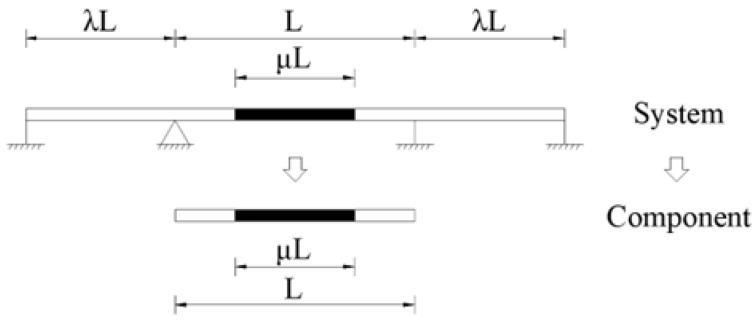 Figure 1
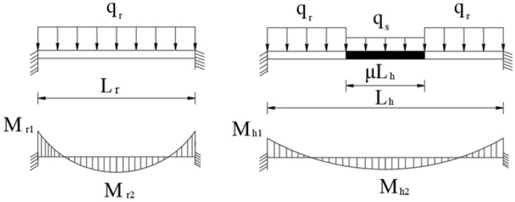 Figure 2
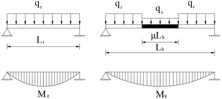 Figure 3
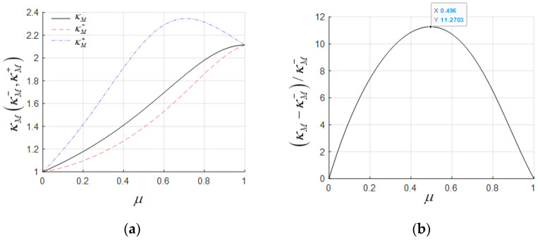 Figure 4
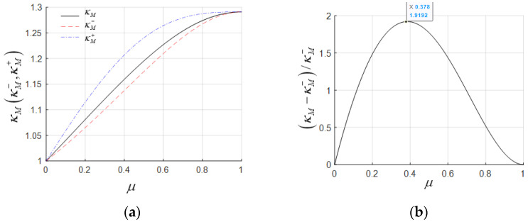 Figure 5
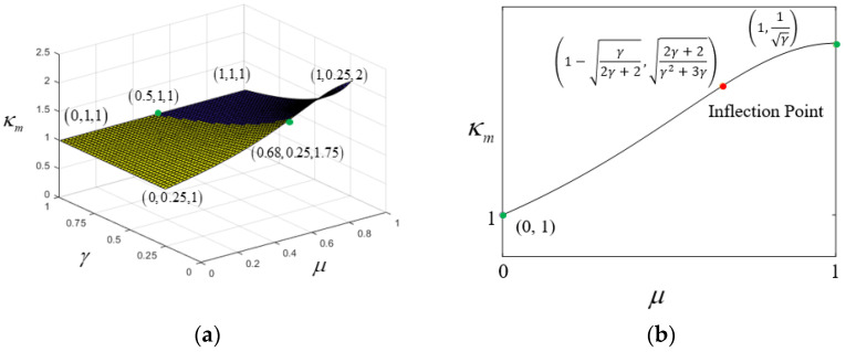 Figure 6
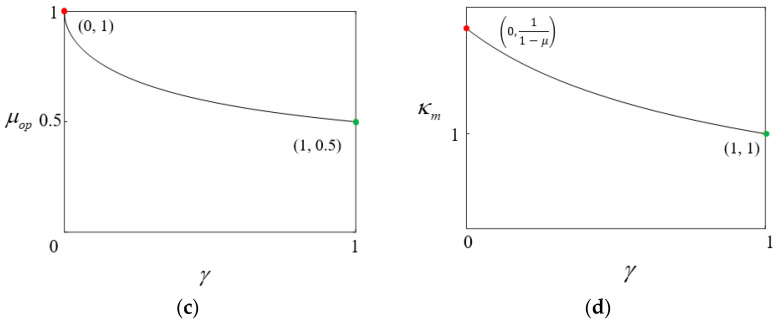 Figure 7
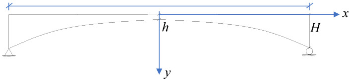 Figure 8
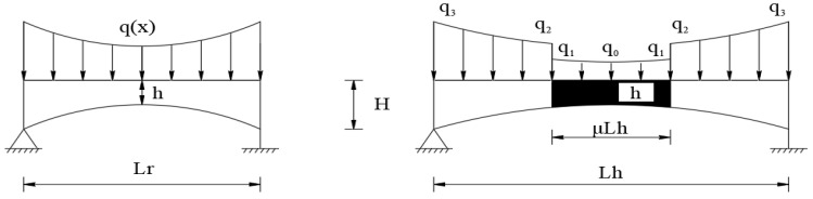 Figure 9
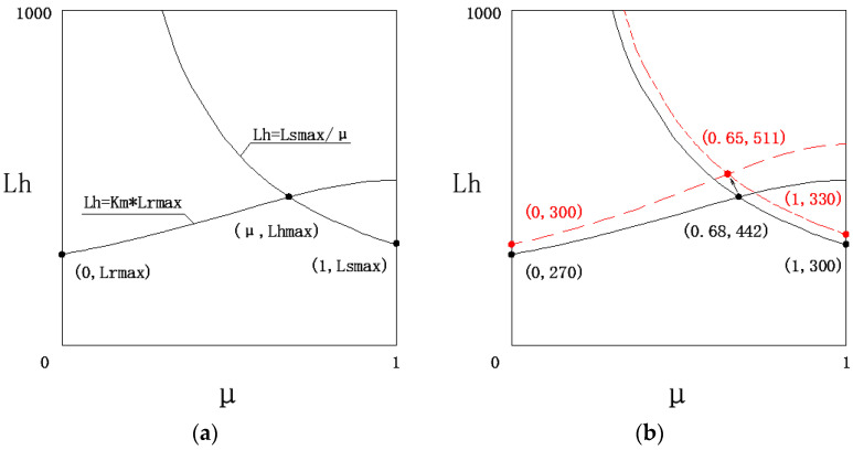 Figure 10
- —Fujian Provincial Department of Transportation
- —Guangdong Yejian Construction Drawing Review Center Co., Ltd.
Peer Reviews
No public reviews on file for this paper yet. If you reviewed it on a platform where reviews are public (OpenReview, ICLR, NeurIPS, ICML), you can paste yours below so the community can read it here.
Videos
No videos yet. Explain this paper in a talk, walkthrough, or lecture? Add one.
Taxonomy
TopicsStructural Engineering and Vibration Analysis · Railway Engineering and Dynamics · Structural Load-Bearing Analysis
1. Introduction
In the 1990s, as large-span prestressed concrete girder bridges began experiencing issues such as web cracking and progressive deflection to varying degrees, hybrid girder bridges emerged as a solution. By using lightweight and high-strength materials in the main girder at the midspan to replace concrete girders, hybrid girder bridges reduced self-weight, allowing for larger bridge spans and mitigating girder deterioration to some extent. Notable examples, such as the Stolma Bridge [1] and the Shibanpo Bridge in Chongqing [2], successively broke the world record for the span of solid-web girder bridges, demonstrating the advantages of hybrid girder bridges.
A hybrid girder bridge is characterized by main girders made of different materials that are effectively connected along the longitudinal direction of the bridge to function as a unified structure under load. This concept is quite similar to plant grafting [3,4,5,6], in which the rootstock, which is connected to the soil, supports the scion, forming a grafted plant. The grafted plant combines the advantages of both the rootstock and the scion, resulting in superior overall performance. Inspired by plant grafting, this paper names the components of hybrid girder bridges as follows: In a hybrid girder bridge, the girder segments not connected to the main foundation of the bridge are called scion beams, while the girder segments connected to the main foundation and bearing the load from the scion beams are referred to as rootstock beams.
Current research on hybrid girder bridges primarily focuses on the mechanical performance of joints [7,8,9,10,11] and system-level analysis. Most studies [12,13,14,15,16,17,18] of the latter category aim to determine the optimal span ratio between side and middle spans, λ, as well as the optimal hybrid ratio, , for three-span hybrid girder bridge systems. However, as the simplified mechanical models for three-span hybrid girder bridges become increasingly refined, the analytical solutions also grow more complex, which, ironically, hinders their practical application in engineering projects. Structural systems are composed of components, and only by conducting in-depth research on the fundamental components can the force characteristics of the entire system be better understood [19]. Given that hybrid girder bridges are primarily bending-dominated structural systems, the study of the bending characteristics of hybrid girder components is particularly significant, as illustrated in Figure 1.
In 2010, Man-Chung Tang [20] proposed the concept of an equivalent span for the Shibanpo Bridge. However, his simplified model, which divided a uniform cross-section beam into three equal parts, could not account for the effects of important factors such as the hybrid ratio, load ratio, stiffness ratio, and beam height on the equivalent span, thereby presenting certain limitations. Drawing on Tang’s concept of equivalent span, this study introduces the Leq Method for analyzing the bending characteristics of hybrid girder components, focusing on the relationship between hybrid girder components and rootstock beam components. For brevity, terms such as “hybrid girder components”, “rootstock beam components”, and “scion beam components” will be abbreviated as “hybrid girder”, “rootstock beam”, and “scion beam”, respectively, in contexts such as model development and formula derivation.
The equivalent span refers to the span of a rootstock beam component that produces the same internal force at the critical section as the hybrid girder component. The ratio of the two spans is defined as the equivalent span increase coefficient, , which is influenced by factors such as the hybrid ratio, , load ratio, , stiffness ratio, , and beam height, h. As the core parameter in equivalent span research, not only reflects the mechanical advantages of hybrid girder components but also serves as a key factor in the system design of hybrid girder bridges, providing valuable guidance for engineering practice. This study aims to propose a simplified formula for and to apply it to guide the conceptual design of hybrid girder bridges.
2. Research Assumptions
The bending model of hybrid girder components is entirely based on elastic linear analysis. Hybrid girder bridges have a low height-to-span ratio, making classical beam theory (Euler–Bernoulli beam) sufficient to meet the accuracy requirements of engineering applications. The computational simplicity of classical beam theory also facilitates the derivation of intuitive analytical solutions. Therefore, in the bending model of the hybrid girder components, both the rootstock beam components and hybrid girder components are assumed to be classical beam elements. This model adheres to the plane section assumption, neglecting the effects of rotational inertia, shear deformation, geometric nonlinearity, material nonlinearity, and temperature. To further derive results with practical engineering significance, the following additional assumptions and conventions are established:
- (1)Load. The load in the bending model of hybrid girder components is represented as a line load perpendicular to the hybrid girder. The intensity of the line load is related to factors such as the material’s unit weight and quantity.
- (2)Cross-sectional properties. The bending model of hybrid girder components is classified into two types based on cross-sectional properties: uniform cross-section beams and variable cross-section beams. For variable cross-section beams, the beam height varies according to a power function with an exponent α.
- (3)Boundary Conditions. The boundary conditions of the bending model for hybrid girder components are classified into two types: fixed at both ends and hinged at both ends. Fixed at both ends (referred to as the fixed-end beam model): This model has complete boundary constraints, capable of providing vertical reactions, horizontal reactions, and fixed-end moments. Additionally, if initial moments are applied at the fixed ends, the model can fully simulate the bending behavior of hybrid girder components. However, the fixed-end beam model involves numerous parameters, making it challenging to derive explicit analytical solutions during theoretical derivations. Hinged at both ends (referred to as the simply supported beam model): This model provides boundary constraints that offer only vertical and horizontal reactions but no fixed-end moments. Despite this limitation, the maximum bending moment, M_max_, in a simply supported beam model is equivalent to the difference, ΔM, between the maximum and minimum bending moments in a fixed-end beam model. Since ΔM and M_max_ have analogous significance in evaluating the spanning capacity of girder bridges, the simply supported beam model holds value as an alternative. Its primary advantage lies in having fewer parameters, which simplifies theoretical analysis and allows for easier derivation of explicit analytical solutions.
- (4)Equivalent internal force terms. When the maximum bending moment of the rootstock beam component is set equal to the maximum bending moment of the hybrid girder component as the equivalence principle, the resulting equivalent span increase coefficient is referred to as the equivalent bending moment span increase coefficient . When the maximum shear force of the rootstock beam component is set equal to the maximum shear force of the hybrid girder component as the equivalence principle, the resulting equivalent span increase coefficient is referred to as the equivalent shear force span increase coefficient .
3. Study on the Equivalent Span of Uniform Cross-Section Hybrid Girders
3.1. κ Based on the Fixed-End Beam Model
When analyzing the coefficient of uniform cross-section hybrid girder components using the fixed-end beam model, the mechanical models and bending moment diagrams of the rootstock beam and hybrid girder are illustrated in Figure 2.
For a fixed-end beam under load, the maximum negative bending moment occurs at the fixed ends, while the maximum positive bending moment occurs at mid-span. Based on the fundamental principles of structural mechanics [21,22], the fixed-end negative bending moments of the rootstock beam and hybrid girder are calculated using Equation (1), and the mid-span positive bending moments of the rootstock beam and hybrid girder are calculated using Equation (2). The derivation of the aforementioned formula is provided in detail in Appendix A.
where = (E_s_I_s_)/(E_r_I_r_) and = q_s_/q_r_.
When M_r_1 = M_h_1, the corresponding L_r_ and L_h_ constitute the equivalent negative bending moment span. The span ratio between the hybrid girder and the rootstock beam is defined as the equivalent negative bending moment span increase coefficient , given by Equation (3):
Similarly, when M_r_2 = M_h_2, the equivalent positive bending moment span increase coefficient is given by Equation (4):
When analyzing the coefficient of uniform cross-section hybrid girder components based on the fixed-end beam model, the maximum shear force of both the rootstock beam and the hybrid girder occurs at the fixed end.
When V_r_ = V_h_, the coefficient is given by Equation (5).
3.2. κ Based on Simply Supported Beam Model
When analyzing the coefficient of uniform cross-section hybrid girder components using the simply supported beam model, the mechanical models and bending moment diagrams of the rootstock beam and hybrid girder are illustrated in Figure 3.
For a simply supported beam under load, the maximum bending moment occurs at mid-span. The mid-span positive bending moments of the rootstock beam and hybrid girder are calculated using Equation (7):
When M_r_ = M_h_, the coefficient is given by Equation (8):
When analyzing the coefficient of uniform cross-section hybrid girder components using the simply supported beam model, the maximum shear forces of the rootstock beam and hybrid girder occur at the supports. When V_r_ = V_h_, the coefficient is also given by Equation (6).
3.3. Comparison of κ
The two models above yield four values, namely, , , and . A comparative analysis is as follows:
Under the condition of a fixed , boundary point analysis is conducted with .
When , ;
When , < ;
As approaches 1, becomes significantly larger than the other three coefficients, and Equation (9) also proves that is consistently greater than . Therefore, shear force is not the controlling factor, and is not suitable as the optimal .
The comparison among , , and is quite challenging, as repeated verification shows that there is no absolute fixed relationship among the three. Below, the differences between , , and are analyzed using two examples of hybrid girders commonly used today: steel-concrete hybrid girders and lightweight concrete hybrid girders.
For a three-span steel-concrete hybrid girder, the steel box girder has a load of 110.29 kN/m, a bending moment of inertia of 2.889 m^4^, and a modulus of elasticity of 2.06 × 10^5^ Mpa. The concrete box girder has a load of 491.78 kN/m, a bending moment of inertia of 37.711 m^4^, and a modulus of elasticity of 3.55 × 10^4^ Mpa. This gives = 0.224 and = 0.444. The calculation results for , , and are illustrated in Figure 4a, where < < . The value is relatively large, and its curve exhibits abnormal non-monotonic growth, leading to failure. In contrast, the curves for , are normal and very close to each other, with a maximum error of 11.27%, as shown in Figure 4b.
For a lightweight concrete hybrid girder with = 0.6 and = 1, the calculation results for , , and are illustrated in Figure 5a. The relationship remains < < . The curves for and are still very close, with a maximum error of 13.99%, as shown in Figure 5b.
In general, negative bending moments play a controlling role in hybrid girder design, making a more accurate choice as the equivalent span length increase factor. From the two examples above, it can be observed that is larger than and deviates significantly, making it unsuitable as the optimal . Meanwhile, and show consistent variation patterns and have minimal numerical differences, each with its own advantages. The expression for (Equation (8)) does not depend on and combines both computational accuracy and a uniquely simple and clear formulation, making it well-suited for use in the conceptual design phase.
3.4. Characteristics of κM
is a bivariate function of and , as expressed in Equation (8). A 3D surface plot of ( (0, 1), (0.25, 1)) has been created, resembling a surface formed by lifting one corner of a rectangular plane, as shown in Figure 6a. Based on mathematical analysis of (detailed in Appendix B), its characteristics are as follows:
- When parameter is constant, within the range (0, 1), ( ) forms a monotonic curve that is initially concave and later convex, with endpoints at (0, 1), (1, ) and an inflection point at , as shown in Figure 6b.
The curve indicates that when is constant, the larger is, the larger becomes. The rate of increase in peaks at the inflection point and then gradually decreases. Therefore, the horizontal coordinate of the inflection point corresponds to the theoretically optimal hybrid ratio , as expressed in the following formula:
Equation (10) indicates that as changes from 1 to 0, the optimal hybrid ratio varies from 0.5 to 1, as shown in Figure 6c.
- When parameter is constant, within the range (0, 1), forms a concave curve with monotonic increase and decrease, with endpoints at and (1, 1), as shown in Figure 6d.
4. Study on Equivalent Span Increase Coefficient of Variable Cross-Section Hybrid Girders
The parameters of the variable cross-section hybrid girder model increase, making it difficult to derive a mechanical analytical solution for using the fixed-end beam model. The derivation in the previous section has already demonstrated that using the simply supported beam model to solve for yields consistent trends with the fixed-end beam model, with acceptable differences. Therefore, this study employs only the simply supported beam model to analyze for variable cross-section hybrid girders, omitting shear force-based coefficient for the same reasons as in the previous section.
The geometric shape of the simply supported variable cross-section girder changes according to a power function, as illustrated in Figure 7. The girder height and load of the variable cross-section hybrid girder are given in Equations (11) and (12):
The corresponding load diagram for the variable cross-section hybrid girder is shown in Figure 8.
Based on the load diagram of the hybrid girder, the following load intensity relationships are expressed in Equation (13):
For a simply supported beam under load, the maximum bending moment occurs at mid-span. The mid-span positive bending moments for both the rootstock beam and the hybrid girder are calculated using Equations (14) and (15):
When the maximum positive bending moments of the rootstock beam and the hybrid girder (M_r_ = M_h_) are equal, can be derived by Equation (16).
5. Engineering Case Comparison of κM Between Uniform and Variable Cross-Sections
To compare the accuracy and differences of between uniform and variable cross-sections, five large-span hybrid girder bridges, both domestic and international, were selected: Stolma Bridge, Shibanpo Bridge, Oujiang Bridge, Anhai Bay Bridge, and Taoer River Bridge. By consulting relevant technical reports [1,23,24,25,26], the equivalent internal force span amplification factors , and were calculated: was calculated using Equation (16); and and were calculated using Equation (8). For , the parameter was determined based on the actual weight ratio of the bridges. For , the parameter was derived based on empirical values. The calculation results are presented in Table 1.
The calculated value using the variable cross-section formula, , is considered the benchmark, as it provides the smallest error. When compared to the results from the uniform cross-section formula, and , the error rate ranges from a maximum of 7.4% to a minimum of 3.2%, which meets the accuracy requirements for conceptual design and scheme design. Among the three coefficients, is called the estimation formula. It only depends on and , and is based on empirical values without the need for calculation. This formula combines computational accuracy with simplicity and clarity, offering unique advantages and broad application value in scheme design.
6. Applications
With the estimation formula, it becomes easier to implement the span design and ultimate span prediction for hybrid girder bridges.
6.1. Span Arrangement Design
Based on the estimation formula, the equivalent span L_eq_ = L/ of the hybrid girder can be calculated. By combining the commonly used edge-to-midspan ratios for continuous beams (or continuous rigid frames) of 0.5~0.68, the appropriate span of the edge spans can be easily arranged.
Table 2 presents the verification results from 14 worldwide typical hybrid girder bridges.
Among the fourteen hybrid girder bridges, only two bridges have side spans that fall outside the reasonable span range due to pier position constraints. This demonstrates the high rationality and practicality of the equivalent internal force span method (Leq Method) in hybrid girder bridge span layout design. Similarly, if the span layout of a hybrid girder bridge is fixed, the equivalent internal force span method (Leq Method) can be used to quickly calculate the reasonable value of .
6.2. Limit Span Prediction
According to engineering practice, the limit span of hybrid girders is related to factors such as the hybrid ratio, the load ratio, and the construction technology of the rootstock girder and scion girder. Among these, is an adjustable factor. As shown in Figure 6b, when changes from 0 to 1, changes from 1 to 1 , and L_h_ changes from L_r_ to L_r_ . When L_r_ < L_s_, the span advantage of the hybrid girder is lost, and the span of the pure scion girder becomes larger. Therefore, the implicit condition for the limit span of the hybrid girder to be greater than the limit span of the root and scion girders is L_r_ L_s_. Substituting = L_s_/L_h_ into Equation (8) gives the following:
Therefore, L_h_ is a monotonic function of L_r_ and L_s_, and the limit span for hybrid girder is given by Equation (18):
Due to construction cost considerations, the rootstock girder in hybrid girder bridges is usually a concrete box girder, while the scion girder can be a corrugated steel web box girder, a steel box girder, or a steel truss girder. Currently, the maximum span for concrete box girders is 270 m (Humen Bridge auxiliary channel bridge), for corrugated steel web box girders is 180 m (Feilong Bridge in Guangxi), for steel box girders is 300 m (Rio-Niterói Bridge in Brazil), and for steel truss girders is 549 m (Quebec Bridge in Canada). The estimated limit spans for various hybrid girders based on the above method are shown in Table 3:
In the three key factors determining the limit span of hybrid girder bridges, L_rmax_ determines the starting height of the limit span of the hybrid girder, (L_h_ = × L_rmax_ curve) determines the height of the increase, and L_smax_ (L_h_ = L_sma_x/ curve) determines the upper limit of the increase, ultimately leading to L_hmax_, as shown in Figure 9a. Improving any one of these three factors can increase the limit span of hybrid girder bridges. Among them, the most significant factor remains . If all three factors are improved simultaneously, the limit span will see a significant increase. Taking the concrete beam–steel box girder hybrid girder bridge as an example, if higher-strength steel is used to reduce the line load intensity ratio from 0.3 to 0.25, the maximum span of the concrete box girder bridge increases from 270 m to 300 m, and the maximum span of the steel box girder bridge increases from 300 m to 330 m. As a result, the upgraded concrete beam–steel box girder hybrid girder bridge’s limit span increases from 442 m to 511 m, as shown in Figure 9b.
7. Conclusions
Through the study of the equivalent span of hybrid girder bridges, this paper draws the following conclusions:
- 1.Research on the equivalent span of hybrid girder bridges in this paper is based on hybrid girder components and does not involve factors such as the span-to-span ratio and boundary conditions in system analysis, making it simpler than system analysis. , as the core indicator in the equivalent span research, not only represents the mechanical advantage of the hybrid girder components but also serves as the key to the design of the hybrid structure beam bridge system.
- 2.Through the study of the bending characteristics of uniform hybrid girder components, it was found that the simply supported beam serves as a reliable substitute in the calculation of . The Equation (8) based on the simply supported beam model does not rely on the stiffness ratio but is only related to and , providing good calculation accuracy. The analysis of the three-dimensional surface and mathematical characteristics of derived from Equation (8) enhances engineers’ understanding of hybrid girders.
- 3.Research on the flexural characteristics of variable cross-section hybrid girders using the simply supported beam model, results in Equation (16). A comparison of five hybrid structure beam bridges with Equation (8) demonstrates that Equation (8) provides sufficient accuracy for conceptual design when empirical values are used. This approach greatly simplifies calculations, highlighting both the simplicity and precision of the equivalent span method.
- 4.The equivalent span method, verified by fourteen hybrid structure beam bridges, effectively resolves span layout design during the conceptual phase of hybrid structure beam bridges. It determines side-span lengths under fixed hybrid ratios or identifies hybrid ratios for fixed span layouts.
- 5.By applying Equation (8) in conceptual design, Equation (18) was derived to predict the limit span of hybrid structure beam bridges. This approach is conceptually clear and yields reliable results.
- 6.The Leq method proposed in this paper also has certain limitations. For example, the hybrid girder component model presented here is based on the mid-span hybrid girder, making it inapplicable to other hybrid girder configurations. Additionally, due to the exclusion of factors such as live load, the calculation accuracy is limited, rendering it suitable only for the conceptual and preliminary design stages of long-span hybrid girder bridges. Addressing these limitations will require further research in the future.
The reference list from the paper itself. Each links out to its DOI / PubMed record.
- 1Ingebrigtsen T. Stolma Bridge, Norway Struct. Eng. Int.1999910010210.2749/101686699780621109 · doi ↗
- 2Deng W.Z. Dai T. Overall Design of the Auxiliary Bridge of Chongqing Shibanpo Yangtze River Bridge Bridge Constr.200662832(In Chinese)
- 3Fuentes I. Stegemann S. Golczyk H. Karcher D. Bock R. Horizontal genome transfer as an asexual path to the formation of new species Nature 201451123223510.1038/nature 1329124909992 · doi ↗ · pubmed ↗
- 4Melnyk C.W. Meyerowitz E.M. Plant grafting Curr. Biol.20152518318810.1016/j.cub.2015.01.02925734263 · doi ↗ · pubmed ↗
- 5Kim G. Le Blanc M.L. Wafula E.K. Depamphilis C.W. Westwood J.H. Genomic-scale exchange of m RNA between a parasitic plant and its hosts Science 201434580881110.1126/science.125312225124438 · doi ↗ · pubmed ↗
- 6Mudge K. Janick J. Scofield S. Goldschmidt E.E. A History of Grafting Hortic. Rev.200935437493
- 7Xu C. Zhang L.P. Su Q.T. Abbas S. Mechanical behavior of a novel steel-concrete joint in concrete-composited hybrid continuous bridges Structures 20223629130210.1016/j.istruc.2021.12.030 · doi ↗
- 8Shangguan B. Su Q.T. Casas Joan R. Su H. Wang S.Y. Zhao R.X. Modeling and testing of a composite steel–concrete joint for hybrid girder bridges Materials 202316326510.3390/ma 1608326537110101 PMC 10144137 · doi ↗ · pubmed ↗