Dataset on the conceptual evaluation of carbon capture rates using Ca(OH)2 in the calcium looping process
Markus Secomandi, Kari Myöhänen, Jouni Ritvanen

TL;DR
This paper presents a dataset showing how adding calcium hydroxide improves carbon capture in industrial processes, offering insights for engineers and researchers.
Contribution
The dataset introduces detailed simulations of Ca(OH)₂ injection effects on carbon capture rates in calcium looping systems.
Findings
Injecting Ca(OH)₂ can increase carbon capture rates from 90% to nearly 99%.
The dataset includes 79 simulated cases with parameters like injection rate and reactor entry point.
The dataset supports model validation and optimization of calcium looping systems.
Abstract
Carbon capture in industrial processes is essential for mitigating climate change, especially in energy-intensive sectors like cement and power generation. Among the available carbon capture technologies, calcium looping (CaL) stands out as a feasible post-process solution, which typically captures around 90% of emitted CO₂. However, injecting calcium hydroxide (Ca(OH)₂) can increase capture rates to about 99%. This dataset illustrates how introducing Ca(OH)₂ can help trap more carbon dioxide in industrial systems, highlighting the importance of key factors such as the injection rate and the reactor entry point. By offering detailed simulations under various conditions, the dataset serves as a resource for engineers and researchers looking to reduce emissions in challenging industrial environments and develop new models to support process design. The dataset consists of results from a…
Genes, proteins, chemicals, diseases, species, mutations and cell lines named across the full text — each resolved to its canonical identifier and authoritative record.
Click any figure to enlarge with its caption.
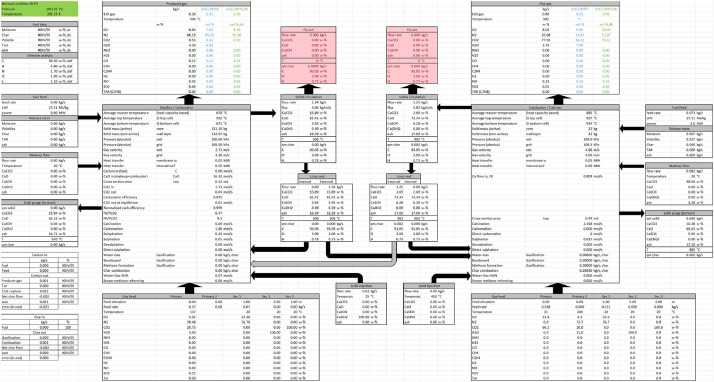 Figure 1
Peer Reviews
No public reviews on file for this paper yet. If you reviewed it on a platform where reviews are public (OpenReview, ICLR, NeurIPS, ICML), you can paste yours below so the community can read it here.
Videos
No videos yet. Explain this paper in a talk, walkthrough, or lecture? Add one.
Taxonomy
TopicsChemical Looping and Thermochemical Processes · Industrial Gas Emission Control · Carbon Dioxide Capture Technologies
Specifications TableSubjectEngineering & Materials scienceSpecific subject areaCarbon capture and storage, calcium looping, reactor modelling, and process optimisation in circulating fluidised bed systems.Type of dataTable (.xlsx format)Data collectionThe dataset was generated using a 1.5D reactor model, which is presented in detail in the related research article [1]. The model simulated the calcium looping process based on the La Pereda pilot plant configuration [2,3]. Input parameters included reactor dimensions, gas and solid flow rates, and injection conditions for Ca(OH)₂. Conservation equations for mass, energy, and species were solved using Simulink ODE solvers. Data include reactor temperature, pressure, gas composition, solid flow rates, and carbonation profiles along the reactor height, calculated under steady-state conditions.Data source locationInstitution: LUT UniversityCity/Town/Region: LappeenrantaCountry: FinlandLatitude and longitude: 61°03′55.0"N 28°05′27.0"EData accessibilityRepository name: ZenodoData identification number: DOI: 10.5281/zenodo.14671741Direct URL to data: https://zenodo.org/records/14671742Related research articleM. Secomandi, M. Nikku, B. Arias, J. Ritvanen. A conceptual evaluation of the use of Ca(OH)2 for attaining carbon capture rates of 99% in the calcium looping process. Int. J. Greenh. Gas Control, 139 (2024), article 104279. https://doi.org/10.1016/j.ijggc.2024.104279.
Value of the Data
1
- •The dataset provides detailed simulation results for 79 cases with different settings, capturing key variables such as reactor temperature profiles, gas and solid compositions, and carbon capture efficiencies in the calcium looping process. These detailed data can assist researchers in understanding and modelling complex calcium looping reactor systems.
- •The data include the effects of Ca(OH)₂ injection on reactor performance, providing insights into the enhancement of carbon capture efficiency. This information is valuable for developing and validating advanced calcium looping models.
- •Researchers can reuse the dataset to explore alternative configurations, refine reactor designs, or compare experimental results with validated model outputs, aiding in process optimisation for novel carbon capture systems.
- •The dataset supports the development of new modelling frameworks or methodologies for simulating circulating fluidised bed reactors, especially for applications requiring high CO₂ capture rates.
- •The data enable sensitivity analyses of critical parameters, such as injection rates and elevations, enhancing the understanding of their influence on reactor performance in carbon capture applications.
Background
2
The dataset was generated to evaluate the potential of calcium hydroxide (Ca(OH)₂) injection to enhance the carbon capture efficiency of the calcium looping process. The simulations were conducted using a 1.5D reactor model developed to study the relationships between key reactor parameters, such as carbon capture, temperature profiles, solid circulation rates, and gas and solid compositions, in a calcium looping system. The dataset is based on the configuration and operating conditions of the La Pereda pilot plant, providing realistic case studies for reactor modelling.
The dataset complements the original research article by offering detailed simulation outputs, which explore the effects of varying injection flow rates, injection elevations, and char combustion profiles on carbon capture efficiency. These files include all modelled parameters, offering a valuable resource for researchers seeking to replicate, validate, or extend the original findings. They also enable further investigation into reactor design and optimisation strategies for high CO₂ capture rates*.*
Data Description
3
The dataset consists of 79 Excel files, each representing a single simulated case. The data used in the original publication are listed in Table 1, where the ending of each filename is given. To obtain the full filename, simply append the corresponding ending found below to ‘CaL1D_results’. For example, data on the cooled case with no char combustion is found in the file ‘CaL1D_results_cool.xlsx’. The dataset also contains 10 additional files containing draft calculations that were not utilised in the actual study.Table 1. The various cases simulated for the original paper [1] and their corresponding Excel files.Table 1. Char combustion profileNone400µm150µmBase case111_this_this_CO_this_this_COfinest_thisCooled case, additional cooling surfaces111_cool_this_CO_cool_this_COfinest_coolCooled case, increased internal circulation1--_this_circcool2--Hydroxide242424- molar ratio = 1; h_inj = 3 m_hydrox_1_3_this_CO_hydr1_3_this_COfinest_1_3- molar ratio = 1; h_inj = 4.5 m_hydrox_1_45_this_CO_hydr1_45_this_COfinest_1_45- molar ratio = 1; h_inj = 6 m_hydrox_1_6_this_CO_hydr1_6_this_COfinest_1_6- molar ratio = 1; h_inj = 7.5 m_hydrox_1_75_this_CO_hydr1_75_this_COfinest_1_75- molar ratio = 1; h_inj = 9 m_hydrox_1_9_this_CO_hydr1_9_this_COfinest_1_9- molar ratio = 1; h_inj = 10.5 m_hydrox_1_105_this_CO_hydr1_105_this_COfinest_1_105- molar ratio = 1; h_inj = 12 m_hydrox_1_12_this_CO_hydr1_12_this_COfinest_1_12- molar ratio = 1; h_inj = 13.5 m_hydrox_1_135_this_CO_hydr1_135_this_COfinest_1_135- molar ratio = 2; h_inj = 3 m_hydrox_2_3_this_CO_hydr2_3_this_COfinest_2_3- molar ratio = 2; h_inj = 4.5 m_hydrox_2_45_this_CO_hydr2_45_this_COfinest_2_45- molar ratio = 2; h_inj = 6 m_hydrox_2_6_this_CO_hydr2_6_this_COfinest_2_6- molar ratio = 2; h_inj = 7.5 m_hydrox_2_75_this_CO_hydr2_75_this_COfinest_2_75- molar ratio = 2; h_inj = 9 m_hydrox_2_9_this_CO_hydr2_9_this_COfinest_2_9- molar ratio = 2; h_inj = 10.5 m_hydrox_2_105_this_CO_hydr2_105_this_COfinest_2_105- molar ratio = 2; h_inj = 12 m_hydrox_2_12_this_CO_hydr2_12_this_COfinest_2_12- molar ratio = 2; h_inj = 13.5 m_hydrox_2_135_this_CO_hydr2_135_this_COfinest_2_135- molar ratio = 3; h_inj = 3 m_hydrox_3_3_this_CO_hydr3_3_this_COfinest_3_3- molar ratio = 3; h_inj = 4.5 m_hydrox_3_45_this_CO_hydr3_45_this_COfinest_3_45- molar ratio = 3; h_inj = 6 m_hydrox_3_6_this_CO_hydr3_6_this_COfinest_3_6- molar ratio = 3; h_inj = 7.5 m_hydrox_3_75_this_CO_hydr3_75_this_COfinest_3_75- molar ratio = 3; h_inj = 9 m_hydrox_3_9_this_CO_hydr3_9_this_COfinest_3_9- molar ratio = 3; h_inj = 10.5 m_hydrox_3_105_this_CO_hydr3_105_this_COfinest_3_105- molar ratio = 3; h_inj = 12 m_hydrox_3_12_this_CO_hydr3_12_this_COfinest_3_12- molar ratio = 3; h_inj = 13.5 m_hydrox_3_135_this_CO_hydr3_135_this_COfinest_3_135
All Excel files are structured in the same way. The ‘Model data’ sheet contains tabled 1D profiles of the most important variables, such as gas and solid compositions, flow rates, temperatures, densities, and reaction rates. The ‘Inputs’ sheet contains tables with information on the different mass flows entering the reactors, whereas the ‘Mass-balances’ and ‘Energy-balances’ sheets contain mass and energy balances. The ‘Fuel-balance’ sheet describes the decomposition of fuel into volatiles and char along with their respective compositions. The ‘0D-results’ sheet presents the main process variables, such as flows entering and exiting each reactor, in a clear diagram (Fig. 1). The remaining sheets consist of graphs of various profiles such as pressures, temperatures, compositions and reaction rates.Fig. 1. Example of 0D-results.Fig. 1
Experimental Design, Materials and Methods
4
Experimental design
4.1
The dataset was generated through simulations using a 1.5D reactor model implemented in the Matlab/Simulink environment. The model was applied to evaluate the effect of calcium hydroxide (Ca(OH)₂) injection on carbon capture efficiency in the calcium looping process, focusing on reactor conditions similar to the La Pereda pilot plant configuration. The simulations covered 79 cases, varying key parameters such as injection flow rate, injection elevation, and char combustion profiles. The latest pilot tests involving Ca(OH)₂ injection suggest that high CO₂ capture efficiencies are achievable in practice. The measurement data are currently being processed and will be used to validate the model once fully compiled.
Reactor model description
4.2
The 1.5D reactor model simulates circulating fluidised bed reactors and incorporates the following:
- •Vertical Segmentation: Reactors are divided into finite volumes along their height to solve mass, energy, and species conservation equations.
- •Radial Segmentation: Each vertical segment is split into a core region and a wall layer to represent internal solids circulation.
- •Chemical Reactions: Includes reactions for carbonation, calcination, char combustion, and the dehydration-carbonation of Ca(OH)₂.
Software and tools
4.3
- •Simulink: Used for implementing and solving the model's ordinary differential equations (ODEs) for transient and steady-state conditions.
- •MATLAB: For parameter input, result processing, and exporting data to Excel files.
Key assumptions and parameters
4.4
- 1.Sorbent and Injection:
- •Make-up flow was calcitic limestone (98.6% CaCO_3_) fed into the calciner.
- •Ca(OH)₂ was injected into the carbonator as fine (10 µm) particles.
- •Injection elevation varied between 3 and 9 meters above the reactor grid.
- 2.Operating Conditions:
- •Carbonator and calciner heights: 15 m.
- •Carbonator gas velocity: 3.4 m/s.
- •Temperatures: Carbonator (550–650°C), Calciner (880–915°C).
- 3.Char Combustion:
- •Two particle size profiles were simulated (150 µm and 400 µm).
- •CO₂ formation rates from char combustion were varied to simulate different combustion rates.
Data acquisition process
4.5
- 1.Base case validation: The model was validated against experimental data from the La Pereda pilot plant. This ensured an accurate representation of reactor behaviour, including temperature and pressure profiles and gas and solid compositions.
- 2.Parameter variation: Key parameters, such as Ca(OH)₂ injection rates (molar ratios of 1–3) and elevations, were systematically varied to generate a comprehensive dataset.
- 3.Simulations: Each case was run under steady-state conditions to obtain reactor profiles for temperature, pressure, gas composition, solid flow, and carbon capture efficiency.
Output data
4.6
For each case, the following data were exported to Excel files solved along the reactor height and for the reactor outlet:
- •Pressure.
- •Temperature.
- •Gas phase composition.
- •Solid phase composition, including CaO, CaCO₃, and char fractions.
- •Carbonation rates and equilibrium conditions.
Additionally, the overall results such as total mass and heat balances of both reactors were reported.
Limitations
None
Ethics Statement
The authors assure that the work and manuscript follow and meet the ethical requirements of the journal. The work does not involve human subjects, animal experiments, or any data collected from social media platforms.
CRediT Author Statement
Markus Secomandi: Writing – original draft, Writing – review & editing, Visualization, Validation, Software, Methodology, Formal analysis, Conceptualization. Kari Myöhänen: Writing – original draft, Writing – review & editing, Data curation. Jouni Ritvanen: Supervision, Software, Methodology, Funding acquisition.
The reference list from the paper itself. Each links out to its DOI / PubMed record.
- 1Secomandi M.Nikku M.Arias B.Ritvanen J.A conceptual evaluation of the use of Ca(OH)2 for attaining carbon capture rates of 99% in the calcium looping process Int. J. Greenh. Gas Control 139202410.1016/j.ijggc.2024.104279 article 104279 · doi ↗
- 2Arias B.Diego M.E.Abanades J.C.Lorenzo M.Diaz L.Martínez D.Alvarez J.Sánchez-Biezma A.Demonstration of steady state CO 2 capture in a 1.7M Wth calcium looping pilot Int. J. Greenh. Gas Control 18201323724510.1016/j.ijggc.2013.07.014 · doi ↗
- 3Arias B.Alvarez Criado Y.Méndez A.Marqués P.Finca I.Abanades J.C.Pilot testing of calcium looping at TRL 7 with CO 2 capture efficiencies toward 99%Energy Fuels.382024147571476410.1021/acs.energyfuels.4c 0247239108832 PMC 11299141 · doi ↗ · pubmed ↗