Evaluating femoral head collapse risk post-fixation removal: a finite element analysis
Xishan Li, Xiang Zhou, Jie Yang, Kai Oliver Böker, Arndt F. Schilling, Wolfgang Lehmann

TL;DR
This study uses computer models to assess how different surgical techniques and bone grafting affect the risk of femoral head collapse after removing internal fixation devices.
Contribution
The study introduces a biomechanical analysis of femoral head collapse risk after fixation removal, comparing different surgical techniques and the effect of bone grafting.
Findings
DHS+CS showed the highest stress in the overall model, while 3CS had the highest stress in the collapse area.
Bone grafting reduced peak stress and strain values compared to normal and sclerotic screw-hole models.
FNS screw holes showed lower mechanical risk, while sclerotic holes increased collapse risk.
Abstract
Femoral neck fractures are prevalent in orthopedic injuries, often leading to complications such as nonunion and osteonecrosis of the femoral head (ONFH). Studies indicate that after healing and removal of internal fixation devices, some patients develop ONFH, while others experience osteosclerosis around the screw holes due to prolonged fixation, increasing ONFH risk. Despite such observations, biomechanical studies on this phenomenon are limited. This study assesses the risk of femoral head collapse post-internal fixation device removal and investigates the biomechanical effects of bone grafting at screw removal sites. Using CT data, femoral anatomy was reconstructed. For control, the femoral head’s collapse area was identified. Experimental models, divided into those with and without bone grafts in screw holes, incorporated three fixation techniques, namely, triple cannulated screws…
Genes, proteins, chemicals, diseases, species, mutations and cell lines named across the full text — each resolved to its canonical identifier and authoritative record.
Click any figure to enlarge with its caption.
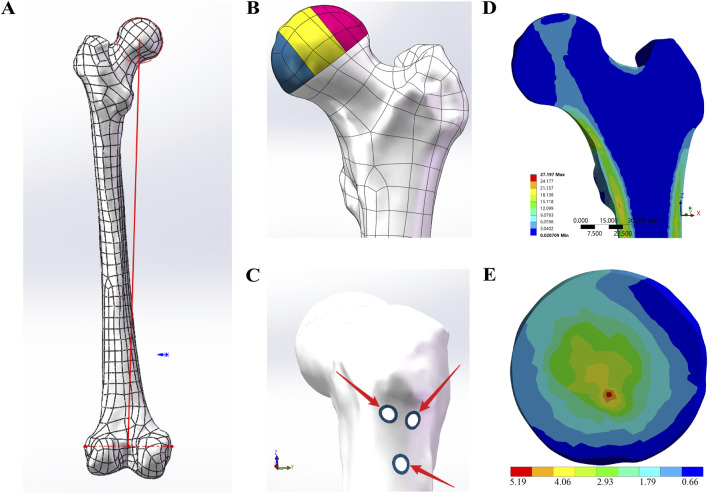 FIGURE 1
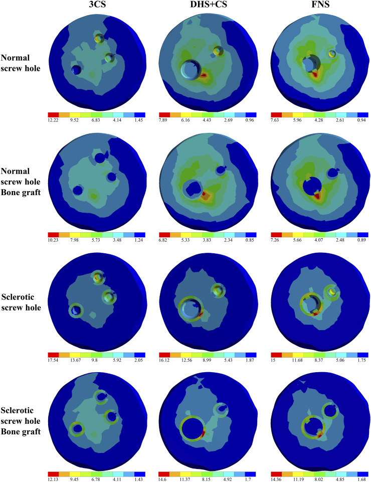 FIGURE 2
| Literature | Stiffness |
|---|---|
|
| 0.757 ± 0.264 |
|
| 0.54 |
| Own | 0.5856 |
| Literature | Maximum von Mises stress |
|---|---|
|
| 22 |
|
| 17.95 |
|
| 17.49 |
|
| 18.05 |
| Own | 17.969 |
| Literature | Maximum von Mises strain |
|---|---|
|
| 0.002 |
|
| 0.0022 |
|
| 0.0023 |
|
| 0.00153 |
| Own | 0.00229 |
| Matthew 2020 | Node 1 | Node 2 | Node 3 | Node 4 | Node 5 | Node 6 | Node 7 | Node 8 |
|---|---|---|---|---|---|---|---|---|
| FE model | 1.749 | 1.008 | 1.561 | 0.476 | 2.954 | 2.089 | 1.103 | 0.694 |
| Cadaver | 2.081 | 0.84 | 2.464 | 0.256 | 3.261 | 2.792 | 1.369 | 0.219 |
| Own | 2.053 | 0.978 | 1.911 | 0.333 | 3.102 | 2.251 | 1.15 | 0.341 |
| Model | Peak (average) stress (Mpa) | Stress index of collapse area | ||||
|---|---|---|---|---|---|---|
| Overall model | Collapse area | Lateral pillar | Central pillar | Medial pillar | ||
| Healthy model | 27.2 (4.16) | 5.19 (1.5) |
| 5.12 (1.73) | 2.42 (0.7) | 0.031–0.052 |
| 3CS | 27.45 (4.23) |
| 5.83 (1.85) |
| 3.67 (0.81) |
|
| DHS+CS |
| 7.89 (1.72) | 5.51 (1.85) |
| 4.36 (1.05) | 0.079–0.047 |
| FNS | 46.66 (4.36) | 7.63 (1.7) | 5.5 (1.83) |
| 4.51 (0.91) | 0.077–0.045 |
| 3CS (bone graft) | 28.44 (4.17) |
| 5.78 (1.82) |
| 3.32 (0.76) |
|
| DHS+CS (bone graft) |
| 6.82 (1.58) | 5.53 (1.8) |
| 3.89 (0.9) | 0.041–0.069 |
| FNS (bone graft) | 44.74 (4.33) | 7.26 (1.58) | 5.55 (1.8) |
| 2.97 (0.86) | 0.043–0.073 |
| Model | Peak (average) stress (Mpa) | Stress index of collapse area | ||||
|---|---|---|---|---|---|---|
| Overall model | Collapse area | Lateral pillar | Central pillar | Medial pillar | ||
| 3CS | 39.57 (4.21) |
| 8.5 (2) |
| 8.16 (0.93) |
|
| DHS+CS |
| 16.12 (1.97) | 8.63 (1.94) |
| 9.99 (1.19) |
|
| FNS | 48.6 (4.37) | 15 (1.96) | 10.76 (1.96) |
| 6.98 (0.85) |
|
| 3CS (bone graft) | 39.48 (4.17) | 12.13 | 6.54 (1.93) |
| 7.18 (0.84) |
|
| DHS+CS (bone graft) |
|
| 6.06 (1.9) |
| 9.95 (1.08) |
|
| FNS (bone graft) | 48.88 (4.33) | 14.36 (1.8) | 10.01 (1.94) |
| 7.49 (0.76) |
|
| Model | Lateral pillar | Central pillar | Medial pillar |
|---|---|---|---|
| Healthy model |
| 2.03e-003 | 1.67e-003 |
| 3CS | 2.81e-003 |
| 2.49e-003 |
| DHS+CS | 3.08e-003 | 3.12e-003 | 3.14e-003 |
| FNS | 3.07e-003 | 3.45e-003 | 2.23e-003 |
| 3CS (bone graft) | 2.81e-003 |
| 2.21e-003 |
| DHS+CS (bone graft) | 2.92e-003 | 2.95e-003 | 3.06e-003 |
| FNS (bone graft) | 2.95e-003 | 3.06e-003 | 2.12e-003 |
| Model | Lateral pillar | Central pillar | Medial pillar |
|---|---|---|---|
| 3CS |
| 2.31e-003 | 1.77e-003 |
| DHS+CS | 2.94e-003 | 2.36e-003 | 2.21e-003 |
| FNS | 2.91e-003 | 2.28e-003 | 1.68e-003 |
| 3CS (bone graft) |
| 2.29e-003 | 1.63e-003 |
| DHS+CS (bone graft) | 2.79e-003 | 2.35e-003 | 2.08e-003 |
| FNS (bone graft) | 2.75e-003 | 2.02e-003 | 1.68e-003 |
Peer Reviews
No public reviews on file for this paper yet. If you reviewed it on a platform where reviews are public (OpenReview, ICLR, NeurIPS, ICML), you can paste yours below so the community can read it here.
Videos
No videos yet. Explain this paper in a talk, walkthrough, or lecture? Add one.
Taxonomy
TopicsHip and Femur Fractures · Pelvic and Acetabular Injuries · Hip disorders and treatments
1 Introduction
Femoral neck fractures are a common type of joint trauma, accounting for nearly 50% of proximal femur fractures (Wang et al., 2019). In Germany, the incidence has increased by 23% over the past decade (Szymski et al., 2023). Furthermore, mortality rates associated with femoral neck fractures remain elevated, ranging at approximately 8.4%–36% within the first year following surgery (Abrahamsen et al., 2009; Mundi et al., 2014). Due to advancements in internal fixation techniques, the healing rate for femoral neck fractures has surpassed 90% (Bhandari and Swiontkowski, 2017). At present, the predominant surgical interventions for femoral neck fractures in patients include triple cannulated screws (3CS), dynamic hip screws with cannulated screws (DHS+CS), and the femoral neck system (FNS) (Huang et al., 2010; Yang et al., 2013; Niemann et al., 2023). Following the healing of femoral neck fractures, the removal of screws is often necessitated due to functional impairment, local irritation, or subjective discomfort experienced by the patient (Hanson et al., 2008; Zielinski et al., 2015). However, some studies suggest that screw removal after femoral neck fracture healing is linked to an increased incidence of osteonecrosis of the femoral head (ONFH). In these cases, nail removal significantly raises the risk of avascular necrosis of the femoral head. The incidence of ONFH in the implant removal group was 4.167 times higher than that in the group without implant removal, and this risk increased to 26.0 times in elderly patients who underwent implant removal (Ai et al., 2013; Li et al., 2018). The femoral neck may be unable to fully withstand these forces, leading to a disruption in the biomechanical stress and load-bearing function of its trabeculae. This disruption can result in microfractures or even re-fractures of the femoral neck (Shah et al., 2015). Additionally, Kim et al. identified a high incidence of hidden ONFH, with MRI detecting 13 cases in 58 patients after fixation removal. Four patients experienced femoral head collapse, one of whom required hip replacement surgery, highlighting the need to carefully select fixation methods that minimize this risk (Kim et al., 2022). Furthermore, the screw hole is the most common and critical contributor that increases the femoral stress and the risk of re-fractures after removing the implant (Zhou et al., 2019), while placing resorbable fillers in bone defects after hardware removal could reduce the risk of re-fractures (Alford et al., 2007). Conversely, a recent study indicated that prolonged retention of the internal fixation implant following surgery for femoral neck fracture can result in osteosclerosis around the screw holes in the femoral head. The presence of sclerotic bone may contribute to the development of ONFH (Liu et al., 2022b). Therefore, the need for screw removal after the union of a femoral neck fracture remains controversial. ONFH, which typically affects the weight-bearing region, is a destructive disease, leading to femoral head collapse. This condition often necessitates total hip arthroplasty. In young patients, the increased incidence of ONFH secondary to femoral neck fracture might be associated with increased daily activity (Goudie et al., 2018). A meta-analysis encompassing 747 patients with FNF, the majority of whom were treated with cannulated screws, revealed that the removal of internal fixation is associated with an increased incidence of ONFH in patients with healed fractures (Jiang et al., 2023). However, the mechanical strength of the femoral head associated with different screw-hole configurations after the removal of internal fixation is also not well-understood, and the biomechanical changes of the screw holes after utilizing the resorbable fillers remain unclear. Thus, it is necessary to investigate the biomechanical behavior of the screw hole in the femoral head after the removal of internal fixation.
We hypothesize that different screw-hole configurations may influence the mechanical strength of the femoral head after internal fixation removal. This study aimed to compare the risk of femoral head collapse by analyzing the biomechanical behavior of varying screw-hole structures and assessing the influence of the sclerotic zone in the femoral head. Additionally, we investigated the biomechanical changes in the femoral head after bone grafting in the screw hole to provide a reference for predicting the risk of femoral head collapse after removing internal fixation.
2 Materials and methods
2.1 Materials
Data: a 50-year-old male patient presented without any historical incidence of femoral trauma. The imaging assessments revealed an absence of tumors, deformities, and fractures. It was provided by the Department of Radiology at the University Medical Center Göttingen.
Computer workstation: processor: Intel(R) Core (TM) i9-10900 K CPU @ 3.70 GHz; installed RAM: 64.0 GB; graphics card: Nvidia Quadro RTX 4000 (8.0 GB).
Software: 3D reconstruction: 3D Slicer 5.0.2 (https://www.slicer.org); 3-Matic 9.0 (Materialise, Leuven, Belgium); Geomagic Wrap 2021 (3D Systems, United States).
Model assembly: Solid Works 2018 (Dassault Systèmes, France).
FE-analysis software: ANSYS 2021R2 (ANSYS, United States).
2.2 Methods
2.2.1 FE-model designs and groups
The healthy femur model was constructed using segmentation and modeling tools in 3D Slicer based on CT scan data. The experimental solid models were created by reverse-engineering the initial femur model into a CAD format using Geomagic Wrap, followed by further modifications in SolidWorks. The coordinates of the lower limb’s mechanical axis were then established (Cooke and Sled, 2009) (Figure 1A). Subsequently, the distal 24 cm of the femur was removed, leaving only the proximal portion for the experiment. The model was then imported into ANSYS for meshing and subsequently into 3-matic. Using established formulas from the previous literature (Wang et al., 2017), the bone density was calculated from CT’s Hounsfield units (HUs), and then, corresponding material properties were applied.
FE-model designs. (A) The red line represents the lower limb mechanical axis, which was used as the coordinate system to define the loading direction in ANSYS. (B) According to the three-pillar classification of ONFH, the collapsed necrotic region of the femoral head was divided into the lateral pillar (colored pink), the central pillar (colored yellow), and the medial pillar (colored blue). (C) The blue sclerotic zone surrounding the screw holes was determined to be 1.3533 mm. (D) Distribution of principal stress from the apex of the femoral head to the calcar in the sagittal view. (E) Stress distribution in the collapse area of the control group.
2.2.1.1 Control group
Based on the three-pillar classification of ONFH (Wen et al., 2020), the collapsed necrotic area of the femoral head was divided into the lateral, central, and medial pillars in a ratio of 3:4:3 to facilitate observation and comparison of the collapse (Figure 1B).
2.2.1.2 Experimental group
Based on data provided by the previous literature reports (Fan et al., 2021; Wang et al., 2021), solid models of the CS, DHS, and FNS were created in SolidWorks. Subsequently, adhering to standard surgical fixation techniques, three distinct internal fixation methods—3CS, DHS+CS, and FNS—were assembled onto the anatomical femur model. Following this, within SolidWorks, various internal fixations were subtracted from the model, thereby leaving screw holes on the femur model. According to the research by Liu et al. (2022a), the average thickness of the sclerotic zone surrounding femoral screw tracks was determined to be 1.3533 mm. Building upon the screw-hole models, a U-shaped entity with a thickness of 1.3533 mm was precisely modeled along the screw holes, as shown in Figure 1C. Within the previously mentioned models, a healthy cancellous bone graft, precisely matching the screw tracks, was used to fill the collapsed necrotic region of the femoral head, thereby creating the bone graft screw-hole models. Finally, the same three-pillar observation region for ONFH was established with reference to the control group model.
2.2.2 In silico FE-model settings and solutions
2.2.2.1 Material properties
Based on Zhan et al. (2024), to construct the femoral model, we first utilized HU values obtained from CT scans to estimate bone density (ρ) using an established correlation.
Subsequently, the elastic modulus (E) and Poisson’s ratio (ν) were calculated based on the derived density using the following relationships:
If
If
In accordance with recent studies on sclerotic bone surrounding femoral head screw paths (Liu et al., 2022b), the sclerotic cortical bone was assigned an elastic modulus of 13,300 MPa and a Poisson’s ratio of 0.3, while the sclerotic cancellous bone was assigned an elastic modulus of 240.07 MPa and a Poisson’s ratio of 0.2. The material properties of the bone graft were modeled after healthy cancellous bone, with an elastic modulus of 121 MPa and a Poisson’s ratio of 0.3 (Hou and Zhu, 2006).
2.2.2.2 Contact conditions
The regions between the three pillars for ONFH, between the pillars and the distal femur, and between the sclerotic zone and the surrounding normal bone were meshed with shared nodes. The contact between the bone graft and either the normal bone or the sclerotic zone is set as bonded.
2.2.2.3 Boundary and loading conditions
The surface of the distal femur was immobilized in all directions. A load of 2,100 N was applied in the direction of the lower extremity mechanical axis at the weight-bearing area of the femoral head.
2.2.3 Evaluation criteria
The collapsed area, which typically occurs in the femoral head and involves the three pillars, was the primary focus of observation. Therefore, the stress distribution and stress index of the collapsed area, as well as the strain range of the three pillars, were analyzed.
Additionally, the peak stress and average stress in the overall model; the collapsed area; and the lateral, central, and medial pillars were examined.
2.2.4 Model validation
The FE models were meshed using 10-node tetrahedral elements, resulting in fine meshes comprising 417,561 elements and 588,262 nodes. Sensitivity analyses indicated that increasing the element density did not enhance the model’s prediction accuracy but did elevate the computational load. Convergence was confirmed when results varied by less than 5% over three consecutive steps of sufficient mesh refinement. The final element size determined through this process was applied uniformly to all FE models. To ensure overall mesh quality, the von Mises stress and surface displacement errors were calculated for each FE model individually (Oefner et al., 2021).
The characteristics of the principal stress transfer path are critical for evaluating femoral biomechanical indices. Figure 1D illustrates the distribution of principal stress from the apex of the femoral head to the calcar in the cross-sectional view. The simulation results align with findings from previous studies (Xiao et al., 2015; Zhou et al., 2015). Furthermore, the shape and location of the biomechanical transfer path correspond closely with the distribution of primary compressive trabeculae (Zhang et al., 2023).
Additionally, FE-analyses in this study were also assessed based on stiffness, maximum von Mises stress, maximum von Mises strain, and 8-node von Mises stress and compared with relevant findings from previous in vitro or finite element analysis studies (Papini et al., 2007; Yosibash et al., 2007; Fu et al., 2012; San Antonio et al., 2012; Chen et al., 2019; Jian-Qiao Peng et al., 2020). As shown in Tables 1–4, the model developed in this study demonstrates good consistency and reliability with previous reports. Therefore, we hypothesize that the FE results can accurately reflect the physical status of the femur and can be used to analyze the impact of different screw track structures on femoral head collapse.
3 Result
3.1 Evaluation of equivalent stress and stress distributions
The peak and average stress values for the health, normal screw hole, and bone graft models are presented in Table 5. In both the normal screw hole and bone graft models, the peak and average stresses in the overall model, collapse area, lateral pillar, central pillar, and medial pillar were higher than those in the healthy model. However, the bone graft models exhibited lower stresses in all areas compared to the normal screw-hole models. In the overall model, the DHS+CS screw-hole configuration showed the highest peak and average stress values in both the normal screw hole and bone graft groups. In the normal screw-hole group, the peak stress of DHS+CS was 50.54 MPa, and the average stress was 4.38 MPa. In the bone graft group, the peak and average stresses were 46.32 MPa and 4.33 MPa, respectively. In the collapse area, the 3CS screw-hole configuration had the highest peak and average stress values for both the normal screw hole and bone graft groups. In the normal screw-hole group, the peak stress of 3CS was 12.22 MPa, and the average stress was 1.72 MPa. In the bone graft group, the peak stress was 10.23 MPa, and the average stress was 1.6 MPa. In the lateral, central, and medial pillars, the highest peak and average stress values were observed in the central pillar for both the normal screw hole and bone graft models. In contrast, the healthy model showed the highest peak and average stresses in the lateral pillar. Regarding the stress index in the collapse area, only the 3CS screw-hole configuration exhibited a value greater than 0.1 in both the normal screw hole and bone graft groups.
The peak and average stress values for the health, sclerotic screw hole, and bone graft models are presented in Table 6. In both the sclerotic screw hole and bone graft models, the peak and average stresses in the overall model, collapse area, lateral pillar, central pillar, and medial pillar were significantly higher than those in the healthy model (Table 1). The bone graft model generally showed lower stress values compared to the sclerotic screw-hole model, except in the DHS+CS and FNS configurations, where the peak stress in the overall model increased. In the overall model, the DHS+CS configuration showed the highest peak and average stress values in both the sclerotic screw hole and bone graft models. In the sclerotic screw-hole models, the peak stress for DHS+CS was 56.75 MPa, and the average stress was 4.45 MPa. In the bone graft group, the peak and average stresses were 61.23 MPa and 14.6 MPa, respectively. In the collapse area, the 3CS configuration had the highest peak and average stress values in the sclerotic screw-hole models. The peak stress for 3CS was 17.54 MPa, and the average stress was 2.01 MPa. In the bone graft group, the highest peak stress was 14.6 MPa of the DHS+CS configuration, while the highest average stress was 1.83 MPa of the 3CS configuration. In the lateral, central, and medial pillars, the highest peak and average stress values were observed in the central pillar for both the sclerotic screw hole and bone graft models. Regarding the stress index in the collapse area, all screw-hole configurations exhibited values greater than 0.1 in both the sclerotic screw hole and bone graft groups.
Figure 1E shows the stress distribution in the collapse area of the healthy model in the control group, while Figure 2 illustrates the stress distribution in the collapse area for different screw-hole configurations in the experimental groups. The sclerotic screw-hole group exhibited the most concentrated stress, primarily around the screw holes, whereas the healthy model showed a more evenly distributed stress pattern. The red areas represent regions of high stress. Comparatively, in the healthy model, the red area was primarily concentrated in the central pillar. In the 3CS screw-hole configuration, the red area was mainly located at the deepest part of the uppermost CS screw hole. In the DHS+CS configuration, the red areas were concentrated in two places: the deepest part of the uppermost CS screw hole and around the DHS screw hole. For the FNS configuration, the red area was primarily around the screw hole of the dynamic rod, with no red stress concentration around the upper anti-rotation screw.
Stress distribution in the collapse area of the experiment models. Screw-hole models were represented as follows: 3CS (triple cannulated screws), DHS+CS (dynamic hip screws with cannulated screws), and FNS (femoral neck system). The red areas represent the stress intensive area.
3.2 Evaluation of the strain range
Table 7 shows the strain ranges of the three pillars for the healthy, normal screw hole, and bone graft models. In general, the strain range across all screw hole configuration models, regardless of bone grafting, exceeded that of the healthy model. The bone graft models consistently exhibited lower strain ranges compared to the normal screw-hole models. In the normal screw-hole models, the 3CS screw-hole configuration resulted in the highest strain range in the central pillar, with a value of 4.18e-003. Similarly, in the bone graft models, the 3CS screw-hole configuration also displayed the largest strain range in the central pillar, with a value of 3.37e-003.
Table 8 provides the strain ranges for the sclerotic screw hole and bone graft models. The bone graft models generally showed reduced strain ranges when compared to the sclerotic screw-hole models. In the sclerotic screw-hole models, the 3CS screw-hole configuration had the largest strain range in the lateral pillar, measuring 3.14e-003. The same configuration in the bone graft models produced the highest strain range in the lateral pillar, with a value of 2.96e-003.
4 Discussion
As the fragile regional blood circulation, biomechanical environment, and anatomical characteristics of the femoral neck, ONFH and nonunion have emerged as the primary complication of femoral neck fracture (Dedrick et al., 1986; Karaeminogullari et al., 2004; Damany et al., 2005). Patients with femoral neck fractures undergoing internal fixation treatment still face a significant risk of developing ONFH within 1–2 years after the removal of internal fixation, even if the fracture has fully healed (Kang et al., 2016). According to a review study, the incidence of ONFH related to the removal of internal fixation is not uncommon (Jiang et al., 2023), which even reached 55.4% (Kim et al., 2022). Some scholars suppose that the occurrence of femoral head necrosis after femoral neck fracture must have biomechanical reasons, and the collapse is a direct consequence of the decreased mechanical performance of the necrotic femoral head. Kim et al. (1991) conducted mechanical testing on the subchondral bone and central cancellous bone of necrotic femoral heads, thereby establishing a direct relationship between the reduction in mechanical properties and the femoral head. Therefore, some researchers advocate that internal fixations cannot be removed (Chu et al., 2020), preferring retention of the implant after femoral neck fracture union to minimize the biomechanical changes (Ai et al., 2013; Li et al., 2018). However, the prolonged retention of the internal fixation implant following surgery for femoral neck fractures could result in osteosclerosis around the screw holes in the femoral head, potentially contributing to the development of ONFH (Liu et al., 2022b). Therefore, we conducted a finite element study considering various screw-hole configurations in the femoral head, along with osteosclerosis around the screw hole, following the union of femoral neck fractures, to explore the biomechanical behavior of the screw hole in the femoral head after the removal of the implant.
This study primarily focuses on analyzing the peak stress, stress index, and strain range in the collapsed region of the femoral head. Evidence suggests that peak stress is a reliable biomechanical marker for assessing the risk of femoral head collapse (Li et al., 2019). According to the classification of three pillars, early-stage femoral head collapse in ONFH may result from microfractures that occur when local von Mises stress exceeds the bone’s yield strength. Following the removal of internal fixation, tensile, compressive, and shear forces concentrate on the original fracture site, disrupting the biomechanical balance of the femoral neck and leading to trabecular adjustments, which increase the risk of microfractures or re-fractures (Shah et al., 2015). The stress index, defined as the ratio of effective stress to yield strength, indicates that bone theoretically yields or fractures when this index exceeds 0.1 (Yang et al., 2002; Wen et al., 2020). Bayraktar et al. reported that the yield strength of femoral bone is 133.6 ± 34.1 MPa, corresponding to a critical stress range of 99.5–167.7 MPa (Bayraktar et al., 2004). The bone fatigue process is characterized by progressive damage, with the total strain range determining the number of cycles required to reach fatigue failure. A negative correlation exists between the total strain range and the number of loading cycles necessary to induce fatigue fractures—larger strain ranges correspond to fewer loading cycles, thereby increasing the likelihood of fatigue (Carter et al., 1981).
According to our results, although the DHS+CS screw-hole configuration showed the highest overall stress in the model, the 3CS configuration exhibited the highest stress, specifically in the collapse area. The 3CS configuration also produced the largest strain range, which was observed in the central pillar of the normal screw-hole models and in the lateral pillar of the sclerotic screw-hole models. In contrast, the FNS screw-hole configuration showed the lowest stress in most indicators, except for stress in the collapse area after bone grafting, where it was not the lowest among the three configurations. Therefore, the FNS screw-hole demonstrates a relatively lower mechanical risk of femoral head collapse. In the three-pillar classification of ONFH, the lateral pillar is the primary biomechanical support of the femoral head and a critical region for predicting collapse (Wen et al., 2020). A possible explanation for our findings is that the 3CS configuration caused two defects in the lateral pillar, whereas the DHS+CS and FNS configurations each resulted in only one defect. Additionally, the anti-rotation screw in the FNS configuration, with its smaller diameter and angled insertion compared to the larger cannulated screw in the DHS + CS configuration, causes relatively less damage to the lateral pillar. The reason why the highest stress occurs in the lateral pillar, while the largest strain range is found in the central pillar for the normal screw hole and bone graft models, yet shifts to the lateral pillar in the sclerotic screw hole and bone graft models, may be explained by findings from Wen et al. Their research indicates that necrosis in the central pillar significantly affects the mechanical behavior of both the lateral and medial pillars, potentially leading to altered stress and strain distribution across these regions (Wen et al., 2017). Additionally, due to the significant role of the proximal femur in human motion and its weight-bearing capability, it undergoes compression, tension, and torsional stresses. Under external forces, structures such as tension trabeculae, compression trabeculae, and the femoral calcar are formed in the proximal femur (Skedros and Brand, 2011). When internal fixation is implanted, some trabeculae are damaged, and after removal, the screw holes remain, with damaged compression trabeculae failing to fully recover. This leads to stress concentration in the deficient areas, particularly at the central pillar. In all screw-hole configurations, the stress level and strain range on the collapse area exceeds that in the healthy model, increasing the risk of femoral head collapse post-implant removal. This finding is consistent with the theory of micro-fracture proposed by Wang T. et al. (2014). Furthermore, a previous finite element analysis also confirmed that the removal of all inverted 3CS, following femoral neck fractures union, will result in the highest concentration of von Mises stress on the femoral head, surpassing the scenario where the implant is retained or the lowest femoral calcar screw is removed first. The improper removal of screws and the resulting load on the femur may indeed be closely associated with the occurrence of ONFH or the recurrence of femoral neck fractures (Wu et al., 2022).
Based on our study results, the sclerotic screw-hole configuration significantly increased stress values compared to the normal screw-hole configuration, while the strain range in the sclerotic screw holes was smaller than that in the normal screw holes, primarily due to the higher elastic modulus of the sclerotic bone. However, this does not imply that sclerotic screw-hole configurations are less prone to collapse clinically. Sclerotic bone forms as a result of long-term cyclic extreme stress, leading to trabecular necrosis and collapse around the screw hole (Liu et al., 2022b). When internal fixation devices are retained, biomechanical stresses primarily concentrate on the internal fixation materials. This increased stress loading induces changes in bone mass and microstructure, resulting in an increased bone volume fraction, quantity of trabeculae, and trabecular diameter (Wang et al., 2012). The normal femoral head is primarily composed of trabecular bone, which possesses a certain degree of elasticity (Goda et al., 2012). This sclerotic bone disrupts the femoral head’s normal elasticity, contributing to trabecular damage and increased bone mass from disuse, often signaling the irreversible progression of femoral head necrosis (Ting et al., 2016; Li et al., 2018). Additionally, the process of bone resorption takes only 3 weeks to alter the trabecular structure, while the process of bone formation requires 3 months to construct new bone with good mechanical properties (Wang C. et al., 2014). The dense plate-like trabeculae formed by sclerosis around the screw hole may hinder the revascularization of the original screw track, which could be one of the reasons why bone reconstruction cannot occur in the screw hole even after implant removal (Liu et al., 2022a).
In our study, the bone graft model showed a decrease in both stress values and strain range compared to those in the pre-grafting conditions. This indicates that bone grafting may reduce the risk of femoral head collapse post-implant removal as the von Mises stress on the weight-bearing region of the femoral head was predominantly borne by the grafted bone rather than the screw hole. Furthermore, grafting cancellous bone within the screw hole can enhance the biomechanical performance of the femoral neck by promoting stress distribution within the weight-bearing region of the bone, thereby mitigating the localized stress concentration and preventing subsequent femoral head collapse. Rosson et al. (1991) pointed out that in young adults, the bone volume at the screw hole is close to normal at 18 weeks after removing the steel plate, and they recommended avoiding full weight-bearing within 4 months after implant removal. Burstein et al. (1972) found that woven bone-filling screw holes could eliminate stress concentration effects around the screw holes within approximately 4 weeks. However, there is still limited research on how to facilitate the rapid restoration of full weight-bearing activity in patients after implant removal, especially concerning the improvement of stress distribution along the screw holes. We hypothesize that bone grafting for the screw hole after implant removal could alleviate von Mises stress concentration on the femoral head without the constraint of full weight-bearing. In response to this phenomenon, the authors suggest that before sclerotic bone forms around the internal fixation, timely removal of the screws and insertion of a new type of high-strength, biodegradable implant with a porous structure that promotes osteogenesis and vascularization could prevent the development of sclerotic bone, thereby halting femoral head necrosis. Alternatively, the development of a biomaterial that mimics the strength and biological function of femoral bone could be used to treat femoral neck fractures, helping in avoiding stress concentration around the implant and reducing the risk of femoral head necrosis.
There are still some limitations in our study. First, it does not account for the effects of surrounding muscles and ligaments on the femur, nor does it consider the potential variations in bone absorption associated with the three internal fixation methods. Second, the mechanical conduction mechanisms involved in femoral head collapse after the removal of internal fixation, following femoral neck fracture, are indeed complex, and our understanding of the exact underlying mechanisms remains incomplete. Third, regarding the changes in the von Mises stress location after bone grafting, we assume that the grafted bone alters the stress distribution, but we still need further studies to explore the mechanics. Additionally, the material properties of grafting bone were defined as normal cancellous. In clinical practice, it is difficult to maintain normal cancellous density in the grafted bone due to the uncontrollable material properties and qualities of the bone graft donor. Although our study provides valuable insights into the biomechanical behavior of screw holes in the femoral head under different conditions, the biomechanical test and the additional clinical trials involving larger patient populations and longer follow-up periods are needed, and we will perform in future studies.
5 Conclusion
The FNS screw hole presents a comparatively reduced mechanical risk of femoral head collapse, which may be attributed to the smaller defects it induces in the lateral pillar. On the other hand, sclerotic screw holes are associated with a higher risk of collapse, whereas bone grafting shows potential in improving biomechanical behavior, possibly decreasing the likelihood of femoral head collapse. This study provides a theoretical biomechanical basis for hip preservation strategies and informs the design of new internal fixation techniques and materials.
The reference list from the paper itself. Each links out to its DOI / PubMed record.
- 1Abrahamsen B.Van Staa T.Ariely R.Olson M.Cooper C. (2009). Excess mortality following hip fracture: a systematic epidemiological review. Osteoporos. Int. 20, 1633–1650. 10.1007/s 00198-009-0920-3 19421703 · doi ↗ · pubmed ↗
- 2Ai Z. S.Gao Y. S.Sun Y.Liu Y.Zhang C. Q.Jiang C. H. (2013). Logistic regression analysis of factors associated with avascular necrosis of the femoral head following femoral neck fractures in middle-aged and elderly patients. J. Orthop. Sci. 18, 271–276. 10.1007/s 00776-012-0331-8 23114858 · doi ↗ · pubmed ↗
- 3Alford J. W.Bradley M. P.Fadale P. D.Crisco J. J.Moore D. C.Ehrlich M. G. (2007). Resorbable fillers reduce stress risers from empty screw holes. J. Trauma 63, 647–654. 10.1097/01.ta.0000221042.09862.ae 18073615 · doi ↗ · pubmed ↗
- 4Bayraktar H. H.Morgan E. F.Niebur G. L.Morris G. E.Wong E. K.Keaveny T. M. (2004). Comparison of the elastic and yield properties of human femoral trabecular and cortical bone tissue. J. Biomech. 37, 27–35. 10.1016/s 0021-9290(03)00257-4 14672565 · doi ↗ · pubmed ↗
- 5Bhandari M.Swiontkowski M. (2017). Management of acute hip fracture. N. Engl. J. Med. 377, 2053–2062. 10.1056/nejmcp 1611090 29166235 · doi ↗ · pubmed ↗
- 6Burstein A. H.Currey J.Frankel V. H.Heiple K. G.Lunseth P.Vessely J. C. (1972). Bone strength. The effect of screw holes. J. Bone Jt. Surg. Am. 54, 1143–1156. 10.2106/00004623-197254060-00001 4652047 · doi ↗ · pubmed ↗
- 7Carter D. R.Caler W. E.Spengler D. M.Frankel V. H. (1981). Fatigue behavior of adult cortical bone: the influence of mean strain and strain range. Acta Orthop. Scand. 52, 481–490. 10.3109/17453678108992136 7331784 · doi ↗ · pubmed ↗
- 8Chen J.Ma J. X.Wang Y.Bai H. H.Sun L.Wang Y. (2019). Finite element analysis of two cephalomedullary nails in treatment of elderly reverse obliquity intertrochanteric fractures: zimmer natural nail and proximal femoral nail antirotation-ΙΙ. J. Orthop. Surg. Res. 14, 422. 10.1186/s 13018-019-1468-3 31823801 PMC 6902592 · doi ↗ · pubmed ↗