Preparation and characterization of RhFe/g-C3N4 nanoparticles for efficient hydrolysis of sodium borohydride
Merve UÇAR KAYA, Mehmet YURDERİ, Mehmet ZAHMAKIRAN

TL;DR
Researchers created a new catalyst using RhFe nanoparticles on graphitic carbon nitride to efficiently produce hydrogen from sodium borohydride.
Contribution
A novel RhFe/g-C3N4 catalyst with high activity and recyclability for sodium borohydride hydrolysis is developed.
Findings
The Rh0.48Fe0.52/g-C3N4 catalyst achieved an H2 generation rate of 4214.02 mL min-1 gcat-1 at 298 K.
The catalyst retained 80.72% of its initial activity after 10 reaction cycles.
The initial turnover frequency was measured at 33.04 min−1.
Abstract
Highly effective graphitic carbon nitride-supported RhFe nanoparticles (RhFe/g-C3N4) were prepared using a simple wet impregnation-reduction method for the hydrolysis of sodium borohydride (NaBH4). The obtained Rh0.48Fe0.52/g-C3N4 catalyst was characterized using advanced analytical/spectroscopic techniques such as inductively coupled plasma-optical emission spectroscopy, scanning electron microscopy, transmission electron microscopy, powder X-ray diffraction, X-ray spectroscopy, and Fourier transform infrared spectroscopy. The catalytic activities of RhFe/g-C3N4 catalysts with varying Rh/Fe molar ratios were investigated, demonstrating superior catalytic activity compared to monometallic Rh and Fe. The initial turnover frequency value of the Rh0.48Fe0.52/g-C3N4 catalyst was calculated as 33.04 min−1 and it showed an H2 generation rate of 4214.02 mL min-1 gcat-1 at 298 K. Furthermore,…
Genes, proteins, chemicals, diseases, species, mutations and cell lines named across the full text — each resolved to its canonical identifier and authoritative record.
Click any figure to enlarge with its caption.
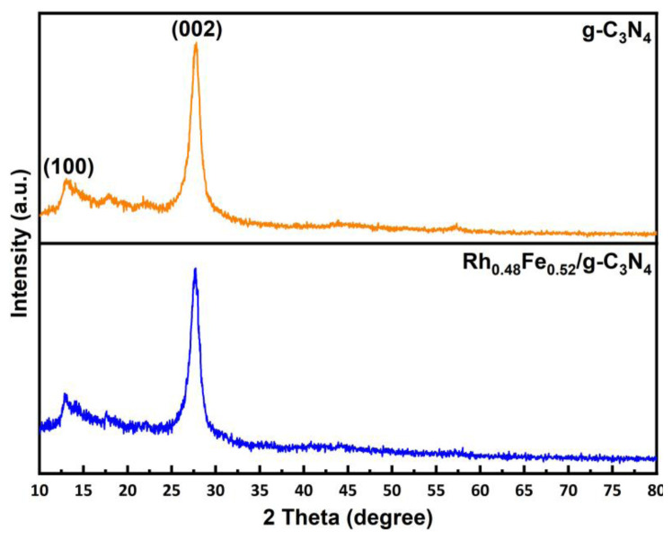 Figure 1
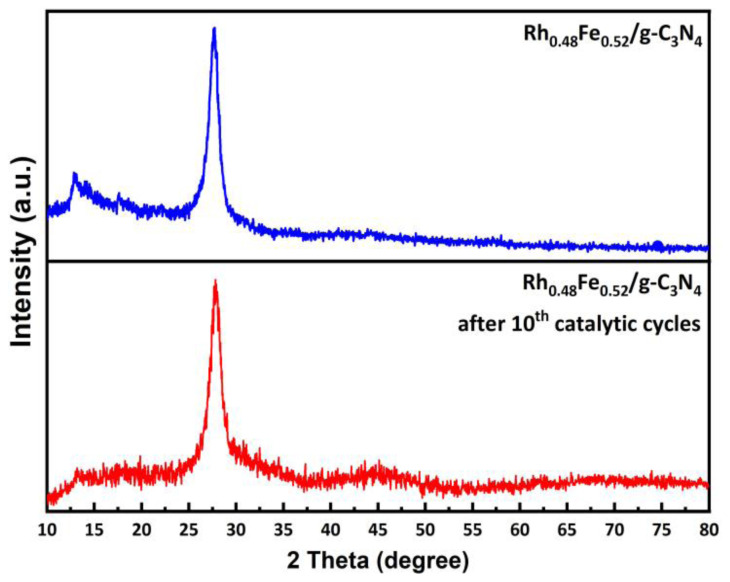 Figure 2
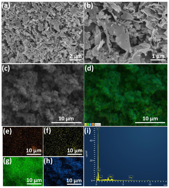 Figure 3
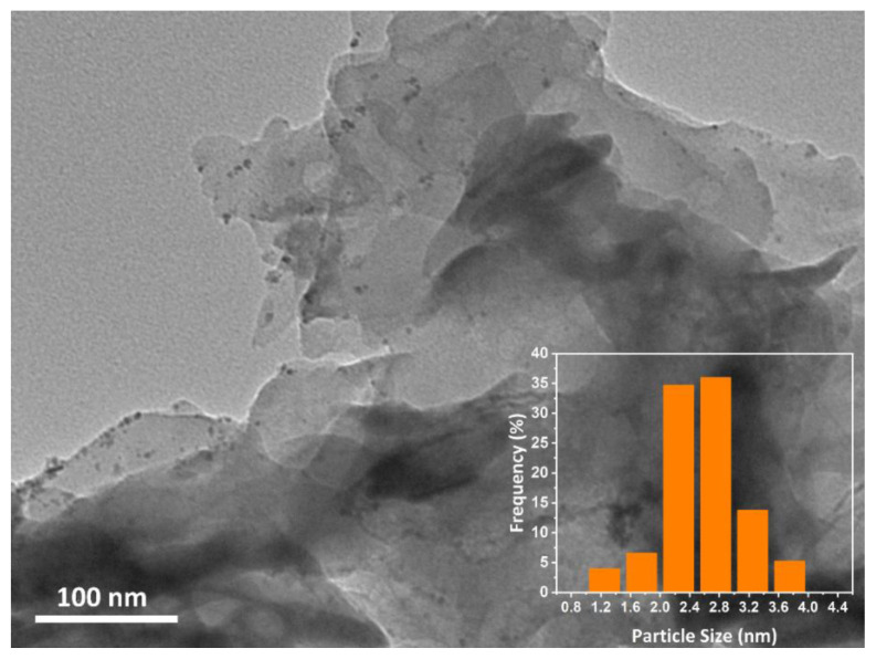 Figure 4
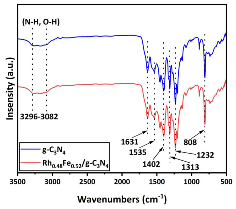 Figure 5
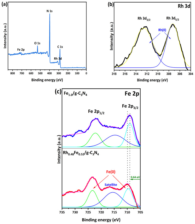 Figure 6
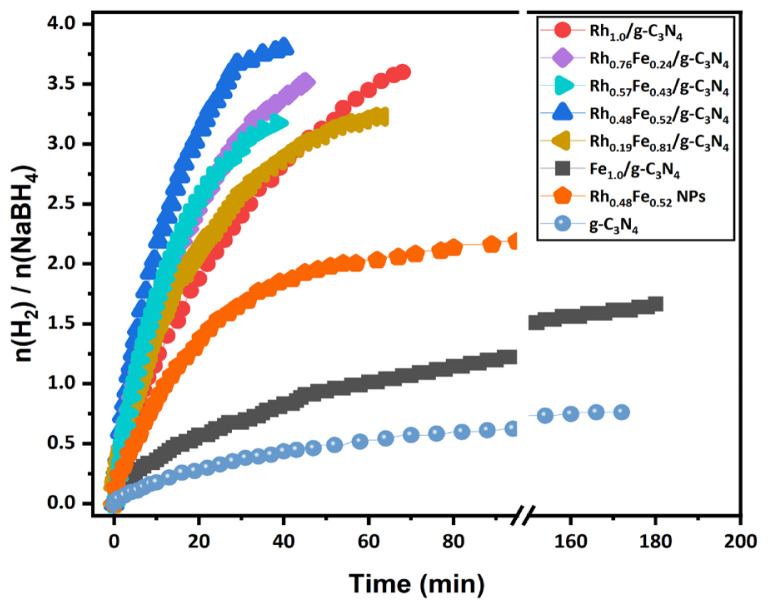 Figure 7
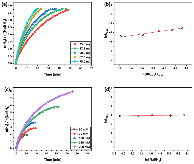 Figure 8
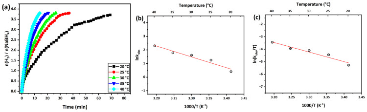 Figure 9
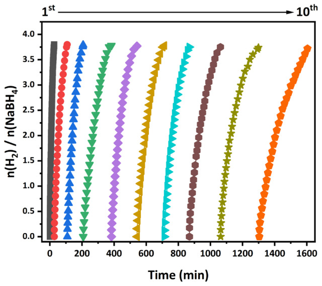 Figure 10
Peer Reviews
No public reviews on file for this paper yet. If you reviewed it on a platform where reviews are public (OpenReview, ICLR, NeurIPS, ICML), you can paste yours below so the community can read it here.
Videos
No videos yet. Explain this paper in a talk, walkthrough, or lecture? Add one.
Taxonomy
TopicsNanomaterials for catalytic reactions · Catalytic Processes in Materials Science · Inorganic Chemistry and Materials
Introduction
One of the scenarios for reducing carbon dioxide (CO_2_) emissions, which contribute to climate change due to fossil fuel consumption, involves using renewable energy and transitioning to a hydrogen economy without carbon emissions. The challenges of this transition include storage and security concerns [1,2]. Among these, boron compounds are promising solid hydrogen (H_2_) storage materials that are widely studied in academia for H_2_ production [3,4]. Sodium borohydride (NaBH_4_) has garnered considerable interest from researchers as a solid hydrogen storage material due to its notable attributes, including a sizable theoretical gravimetric H_2_ storage capacity of 10.8 wt% (or volumetric H_2_ storage capacity of 115 kg m^−3^), cost-effectiveness, nontoxicity, stability, nonflammability, favorable reaction conditions, ease of storage, and environmentally friendly byproducts upon release [5,6]. Conventional methods for releasing the H_2_ stored in NaBH_4_ include pyrolysis and hydrolysis. Generally, pyrolysis requires a high temperature (~400°C), leading to high energy consumption unsuitable for practical applications. However, with suitable catalysts, the hydrolysis of NaBH_4_ easily releases 4 moles of H_2_, even at room temperature Eq. (1) [5,7,8]:
A low-cost catalyst with high catalytic efficiency and stability is vital in practical fuel cell applications. Recent research has focused on developing bimetallic catalysts incorporating cheaper, abundant first-row transition metals to reduce the consumption of expensive precious metals. Employing nonprecious metals to prepare bimetallic catalysts reduces the cost and secondary precious metal content [9–11]. These bimetallic catalysts often exhibit enhanced catalytic efficiency compared to monometallic catalysts due to synergistic effects [12,13].
The nanoparticles (NPs) in the catalyst tend to aggregate into larger particles, blocking active sites and reducing catalytic performance, especially during recyclability tests. Therefore, solid support materials are essential to prevent active site blockage and metal leaching. In heterogeneous catalysis, the interaction between metal NPs and support materials positively enhances the catalyst’s performance [14–17]. Graphitic carbon nitride (g-C_3_N_4_), a two-dimensional (2D), metal-free organic polymer material, can be easily prepared via pyrolysis reaction and emerges as an interesting solid support material for stabilizing NPs. To the best of our knowledge, g-C_3_N_4_ is used in many application areas, such as H_2_ production [18], pollutant degradation [19], water splitting [20], and hydrogen peroxide production [21], owing to its affordability, environmental friendliness, and unique physicochemical and structural properties [22,23]. Therefore, substantial effort is required to investigate the utilization of g-C_3_N_4_ as a solid support material.
The motivation herein was to develop stable and efficient bimetallic catalysts for NaBH_4_ hydrolysis, combining precious metals such as Pt, Ru, and Rh with nonprecious metals like Ni, Co, Cu, and Fe. Hence, this study presents g-C_3_N_4_-supported rhodium/iron (RhFe) (RhFe/g-C_3_N_4_) NPs via the impregnation-reduction method and H_2_ production in the hydrolysis of NaBH_4_ at 298 K. Moreover, the obtained catalyst was characterized by advanced analytical methods like inductively coupled plasma-optical emission spectroscopy (ICP-OES), scanning electron microscopy (SEM), electron microscopy (TEM), powder X-ray diffraction (P-XRD), X-ray spectroscopy (XPS), and Fourier transform infrared spectroscopy (FTIR).
Materials and methods
2.1. Chemicals
The rhodium(III) chloride hydrate (RhCl_3_·xH_2_O, trace metals basis, 99.95%), sodium borohydride NaBH_4_, (ReagentPlus, 99%), iron(III) chloride hexahydrate (FeCl_3_·6H_2_O, American Chemical Society (ACS) reagent, 97%), hydrochloric acid (HCI, ACS reagent, 37%), sodium hydroxide (NaOH, ACS reagent, ≥97.0%), urea (CH_4_N_2_O, ACS reagent, 99.0%–100.5%), and Whatman qualitative filter paper (Grade 5, diameter: 110 mm) were all purchased from Sigma-Aldrich (Sigma-Aldrich Chemical Co., St. Louis, MO, USA).
2.2. Characterization
The content of the elements in the catalyst was measured using an Optima 4300DV ICP-OES (PerkinElmer Inc., Waltham, MA, USA). SEM images were acquired by a Tescan MAIA3 XMU microscope (Tescan, Brno, Kohoutovice, Czech Republic). The surface morphology and particle size analysis of the catalyst were characterized by TEM (Jeol-2100F; Jeol Ltd., Akishima, Tokyo, Japan) at an accelerating voltage of 200 kV. P-XRD patterns were recorded using a SmartLab X-ray diffractometer (Rigaku Corp., Tokyo, Japan) with Cu K_α_ radiation (λ = 1.5418 Å) operating at 40 kV and 55 mA. The surface composition and chemical states of the catalyst components were measured using an ESCA-LAB 250xi XPS (Thermo Fisher Scientific Inc., Waltham, MA, USA) equipped with an Al K_α_ X-ray excitation source. FTIR was performed using a Shimadzu IRTracer-100 spectrometer (Shimadzu Corp., Kyoto, Japan).
2.3. Synthesis of the g-C3N4
The g-C_3_N_4_ synthesis was carried out according to the method in the literature [24]. The starting material, urea (CH_4_N_2_O), was put into a high-quality alumina crucible and placed in a muffle furnace. Then, the muffle furnace was heated at a rate of 2 °C/min, and the sample was kept at 550 °C for 3 h. After cooling to room temperature, the obtained yellow powder was stored in a desiccator, to be used in the catalytic studies.
2.4. Preparation of the RhFe/g-C3N4 NPs
First, 150 mg of g-C_3_N_4_ was added to 10 mL of H_2_O and ultrasonicated for 15 min to form a well-dispersed suspension. Then, RhCl_3_·xH_2_O (0.015 mmol) and FeCl_3_·6H_2_O (0.014 mmol) aqueous solution were added, and the mixture was stirred with a magnetic stirrer at 700 rpm for 3 h. Next, NaBH_4_ (0.49 mmol) was added dropwise to the mixed solution at the molar ratio metal(s): NaBH_4_ = 1:15. The final mixture was washed with water/ethanol and filtered with Whatman No. 5 filter paper. The obtained sample was dried in an oven at 80 °C for 1 h. The dried sample was then stored in a desiccator for use in the catalytic experiment.
2.5. Catalytic hydrolysis of NaBH4 catalyzed by RhFe/g-C3N4
First, 50.0 mg of the RhFe/g-C_3_N_4_ catalyst was added to 4.0 mL of deionized water in a 30-mL jacketed Schlenk flask and placed in a thermostat water bath. The mixture was then stirred at 700 rpm and maintained at the desired temperature for 15 min to reach thermal equilibrium. Subsequently, the jacketed Schlenk flask was sealed with an airtight septum to initiate the reaction, followed by injecting 1.0 mL of NaBH_4_ solution (1 mmol) into the system using an airtight syringe. The volume of H_2_ released during the catalytic hydrolysis of NaBH_4_ catalyzed by the RhFe/g-C_3_N_4_ catalyst was monitored by measuring the water-displacement method in a 200-cm^3^ gas burette [25–27]. Upon completion of the NaBH_4_ hydrolysis, the recorded gas volume (in mL) over time was imported into Origin 10.1 software (OriginLab Corp., Northampton, MA, USA) to generate corresponding graphs.
Results
The g-C_3_N_4_ was synthesized by keeping the starting material (urea, CH_4_N_2_O) in a muffle furnace at 550 °C for 3 h. Then, RhFe NPs were decorated on the g-C_3_N_4_ surface using the impregnation-reduction method following a previously reported procedure. The RhFe/g-C_3_N_4_ bimetallic catalyst was obtained as dark gray powder and determined using ICP-OES, SEM, TEM, P-XRD, XPS, and FTIR analyses.
ICP-OES analysis was used to determine the elemental composition of the RhFe/g-C_3_N_4_ catalyst. The molar composition of the Rh and Fe in the prepared RhFe/g-C_3_N_4_ catalyst was Rh_0.48_Fe_0.52_/g-C_3_N_4_ (0.38% wt Rh and 0.54% wt Fe). P-XRD analysis of the crystal and phase structures of the g-C_3_N_4_ and g-C_3_N_4_-supported Rh_0.48_Fe_0.52_ NPs are given in Figure 1. The Bragg diffraction peaks located at 12.96° (weak, corresponding to the in-plane structural motif of tris-triazine units) and 27.60° (strong, belonging to the interlayer stacking of the C_3_N_4_ layered structure) were attributed to the (100) and (002) crystal planes of the g-C_3_N_4_, respectively. These two Bragg diffraction peaks were consistent with g-C_3_N_4_, as reported in the literature [28,29]. The P-XRD pattern in Figure 1 shows that the crystal structure of the g-C_3_N_4_ in the Rh_0.48_Fe_0.52_/g-C_3_N_4_ catalyst was not affected by the decoration of the Rh_0.48_Fe_0.52_ NPs. Moreover, the Bragg diffraction peaks in the P-XRD corresponding to the Rh_0.48_Fe_0.52_ NPs could not be observed due to the low content of the Rh_0.48_Fe_0.52_ NPs (<5 wt%) and the good dispersion [30].
The SEM images (Figures 2a–2c) and their elemental composition mapping were used to analyze the provided information regarding the surface topography of the catalyst. The elemental mapping given in Figures 2d–2h shows that the Rh, Fe, C, and N in the Rh_0.48_Fe_0.52_/g-C_3_N_4_ catalyst were distributed homogeneously without any accumulation. Moreover, the SEM-EDX spectrum taken from a certain area confirmed the existence of the four elements (Figure 2i).
At the same time, TEM analysis was used to determine the distribution and size of the NPs. Based on the TEM image (Figure 3) analysis conducted using ImageJ (US National Institutes of Health, Bethesda, MD, USA), the sample revealed approximately >94 RhFe NPs decorated on the g-C_3_N_4_ surface. The analysis further yielded an average particle size of 2.68 ± 0.63 nm (inset, Figure 3), indicating a uniform distribution of RhFe NPs with a relatively small size.
FTIR analysis was used to investigate the chemical bonding structures of the g-C_3_N_4_ and Rh_0.48_Fe_0.52_/g-C_3_N_4_ samples (Figure 4). The characteristic peaks detected at approximately 1232, 1313, 1402, 1535, and 1631 cm^−1^ corresponded to the vibrations of C–N [31,32]. The peak at 808 cm^−1^ belonged to the individual breathing mode of triazine rings [33]. Moreover, the broad bands at 3082–3296 cm^−1^ were attributed to N–H and O–H stretching vibration modes [34,35]. Furthermore, the structure of the g-C_3_N_4_ was not affected due to the decoration of the Rh_0.48_Fe_0.52_ NPs.
XPS analysis was conducted to elucidate the composition and chemical state of the Rh_0.48_Fe_0.52_/g-C_3_N_4_ catalyst. As depicted in Figure 5a, the surface XPS spectrum exhibited signals attributed to Rh, Fe, C, N, and O, affirming the successful attachment of Rh and Fe to the g-C_3_N_4_ surface. In the high-resolution (HR) Rh 3d XPS spectrum given in Figure 5b, the two central peaks at 307.27 and 312.58 eV are the Rh 3d_5/2_ and Rh 3d_3/2_ peaks of Rh(0), respectively [36]. The HR Fe 2p core-level spectrum of the Fe 2p_3/2_ exhibits two peaks at 709.0 and 722.2 eV associated with the Fe 2p_3/2_ and Fe 2p_1/2_ peak of Fe(0) for Rh_0.48_Fe_0.52_/g-C_3_N_4_ (Figure 5c) [37,38]. The binding energies of Fe(0) 2p_3/2_ and Fe(0) 2p_1/2_ for the Rh_0.48_Fe_0.52_/g-C_3_N_4_ exhibit an upshift of ~0.64 eV compared to Fe_1.0_/g-C_3_N_4_. This indicates that there was electron transfer between the Rh and Fe. This can be corroborated by examining Figure 6. The catalysts consisting of only Rh_1.0_/g-C_3_N_4_ and Fe_1.0_/g-C_3_N_4_ had much lower catalytic activities toward NaBH_4_ hydrolysis. However, the Rh_0.48_Fe_0.52_/g-C_3_N_4_ bimetallic catalyst had much better catalytic activity.
The molar metal composition (Rh/Fe) impacted the performance of RhFe/g-C_3_N_4_ in the hydrolysis of NaBH_4_. H_2_ production via the hydrolysis of NaBH_4_ was evaluated using mono/bimetallic catalysts (Rh_1.0_/g-C_3_N_4_, Fe_1.0_/g-C_3_N_4_, Rh_x_Fe_1-x_/g-C_3_N_4_) prepared in NaBH_4_ aqueous solution at 298 K. Figure 6 shows the time-dependent H_2_ evaluation graph in NaBH_4_ hydrolysis catalyzed by RhFe/g-C_3_N_4_ catalysts with different Rh/Fe molar ratios. The graph shows that the Rh_1.0_/g-C_3_N_4_ and Fe_1.0_/g-C_3_N_4_ catalysts produce 3.6 moles of H_2_ in 68 min and 1.66 moles of H_2_ in 180 min in the NaBH_4_ hydrolysis, which indicates that the Rh/g-C_3_N_4_ and Fe/g-C_3_N_4_ catalysts alone could not release 4 moles of H_2_ from NaBH_4_ hydrolysis. As the molar ratio between the Rh and Fe in the Rh_x_Fe_1-x_/g-C_3_N_4_ catalyst changed, the catalytic efficiency in the NaBH_4_ hydrolysis increased. The catalytic activities obtained in the bimetallic Rh_0.48_Fe_0.52_/g-C_3_N_4_ catalysts were compared to the monometallic Rh_1.0_/g-C_3_N_4_ and Fe_1.0_/g-C_3_N_4_ catalysts in terms of the initial turnover frequency (TOF) values. Among the bimetallic catalysts in the graph, the optimized Rh_0.48_Fe_0.52_/g-C_3_N_4_ catalyst provided the highest activity in the hydrolysis of NaBH_4_, with an initial TOF value of ~3.9 moles of H_2_ in 40 min. Moreover, the Rh_0.48_Fe_0.52_/g-C_3_N_4_ catalyst exhibited a TOF value of , which was higher than those of the and colloidal Rh_0.48_Fe_0.52_ NPs without . The effect of the g-C_3_N_4_ on NaBH_4_ hydrolysis was also investigated without impregnation of the Rh_0.48_Fe_0.52_ NPs, and it was observed that g-C_3_N_4_ exhibited very low catalytic activity compared to the Rh_0.48_Fe_0.52_/g-C_3_N_4_ catalyst.
The effect of the amount of [Rh_0.48_Fe_0.52_] on the hydrolysis of NaBH_4_ over the Rh_0.5_Fe_0.5_/g-C_3_N_4_ catalyst was investigated across amounts of [Rh_0.48_Fe_0.52_] ranging from 25 to 75 mg ([NaBH_4_] = 100 mM, 298 K). Figure 7a depicts the volumetric H_2_ released over time during hydrolysis of the NaBH4 on the Rh_0.48_Fe_0.52_/g-C_3_N_4_ catalyst at varying amounts [Rh_0.48_Fe_0.52_]. As seen in the graph, the hydrolysis time of NaBH_4_ increased as the amount of [Rh_0.48_Fe_0.52_] increased from 25 to 75 mg (25, 37.5, 50, 62.5, and 75.0 mg amount of catalyst correspond to 0.95, 1.42, 1.9, 2.37, and 2.84 mM RhFe concentrations). The H_2_ evolution rates for the different amounts of [Rh_0.48_Fe_0.52_] were determined by examining the linear parts of each plot in Figure 7b. The resulting linear part gave a slope of 0.94, indicating that the catalytic process of NaBH_4_ hydrolysis by Rh_0.48_Fe_0.52_/g-C_3_N_4_ adhered to first-order kinetics. Figure 7c shows the effect of different [NaBH_4_] concentrations on the hydrolysis of NaBH_4_ catalyzed by Rh_0.48_Fe_0.52_/g-C_3_N_4_ (catalyst = 50 mg, 298 K]). The slope was calculated as 0.06 from the logarithmic graph of H_2_ evolution rates obtained from each graph in Figure 7d. This indicates that the hydrolysis of NaBH_4_ catalyzed by Rh_0.48_Fe_0.52_/g-C_3_N_4_ was a zero-order reaction related to the [NaBH_4_] concentration. The temperature effect on the H_2_ evolution rate in the NaBH_4_ hydrolysis catalyzed by Rh_0.48_Fe_0.52_/g-C_3_N_4_ was also examined (catalyst = 50 mg, [NaBH_4_] = 100 mM).
Figure 8 shows the volumetric H_2_ release versus time plot for hydrolysis of the NaBH_4_ on the Rh_0.48_Fe_0.52_/g-C_3_N_4_ catalyst at different temperatures (20, 25, 30, 35, and 40 °C). In the graph, the H_2_ evolution rate also increased with temperature, which shows that temperature seriously impacted the H_2_ formation rate in hydrolysis of the NaBH_4_. The activation energy (Ea^#^) is a critical metric for investigating the catalytic process of NaBH_4_ hydrolysis. The Ea^#^ value for the hydrolysis reaction catalyzed by the optimized Rh_0.48_Fe_0.52_/g-C_3_N_4_ bimetallic catalyst was determined using the Arrhenius equation. In Figures 8b and 8c, the rate constants calculated from the linear part of each graph were transferred to the Arrhenius and Eyring equations and calculated as Ea^#^ 66.20 kJ mol^−1^, activation enthalpy (ΔH^#^) 63.68 kJ mol^−1^, and activation entropy (ΔS^#^) −149.53 J mol^−1^ K^−1^.
The Ea^#^ for the Rh_0.5_Fe_0.5_/g-C_3_N_4_ was lower than most of the catalysts reported in Table, indicating that this catalyst can remarkably reduce the energy barrier for NaBH_4_ hydrolysis, thus facilitating the formation of H_2_ from NaBH_4_ hydrolysis under mild conditions.
Moreover, the stability of the catalyst is significant for use in large-scale industrial production. The recyclability performance of the Rh_0.48_Fe_0.52_/g-C_3_N_4_ catalyst for the hydrolysis of NaBH_4_ up to the 10th catalytic cycle is given in Figure 9. Following completion of the 1st cycle, fresh NaBH_4_ solution was added to the reaction medium, and catalytic testing continued through the 10th cycle. The Rh_0.48_Fe_0.52_/g-C_3_N_4_ catalyst catalyzed the hydrolysis of NaBH_4_ to produce about ~4 equivalent of H_2_ per mole of NaBH_4_. As the number of cycles increased, the conversion time of the NaBH_4_ also increased slightly. This indicates a decrease in activity, which caused the accumulation of NaBO_2_ [51], a byproduct formed in the solution with each addition of NaBH_4_ to the system. Therefore, this shows that it blocked the catalyst’s active sites and prevented contact between the catalyst and the NaBH_4_ solution.
The P-XRD pattern of the Rh_0.48_Fe_0.52_/g-C_3_N_4_ catalyst taken after 10 cycles (Figure 10) was the same as that of the Rh_0.48_Fe_0.52_/g-C_3_N_4_, indicating that the crystallinity of the solid support material (g-C_3_N_4_) was maintained after 10 cycles.
Discussion
The preparation of a RhFe/g-C_3_N_4_ catalyst via a simple and reproducible impregnation-reduction method in a 4-h procedure was presented. The optimized Rh_0.48_Fe_0.52_/g-C_3_N_4_ catalyst exhibited outstanding performance with an initial TOF of 33.04 mol_H2_ mol^−1^metal_h^−1^ and an H_2 generation rate (HGR) of at 298 K. The catalytic activity of the Rh_0.48_Fe_0.52_/g-C_3_N_4_ in the hydrolysis of NaBH_4_ was evaluated under different temperatures, concentrations of [RhFe NPs] and [NaBH_4_], and recyclability conditions. The activation parameters (Ea^#^, ΔH^#^, ΔS^#^) for hydrolysis of the NaBH_4_ catalyzed by Rh_0.48_Fe_0.52_/g-C_3_N_4_ were calculated as 66.20 kJ mol^−1^, 63.68 kJ mol^−1^, and −149.53 kJ mol^−1^ K^−1^, respectively. Moreover, the resulting Rh_0.48_Fe_0.52_/g-C_3_N_4_ catalyst was recyclable and retained 80.72% of the initial activity even after 10 runs. These findings highlight the potential of Rh_0.48_Fe_0.52_/g-C_3_N_4_ catalysts for efficient H_2_ production, paving the way for their application in fuel cell-based H_2_ economies.
The reference list from the paper itself. Each links out to its DOI / PubMed record.
- 1Long B Chen J Sharshir SW Ibrahim L Zhou W The mechanism and challenges of cobalt-boron-based catalysts in the hydrolysis of sodium borohydride Journal of Material Chemistry A 2024 12 10 5606 5625 10.1039/D 3TA 07308 D · doi ↗
- 2Pope F Jonk J Fowler M Lan PCM Geels NJ From shrimp balls to hydrogen bubbles: borohydride hydrolysis catalysed by flexible cobalt chitosan spheres Green Chemistry 2023 25 14 5727 5734 10.1039/D 3GC 00821 E · doi ↗
- 3Netskina OV Bulakov VE Sukhorukov DA Ozerova AM Prosvirin IP Ferromagnetic “nickel core–cobalt shell” catalysts for Na BH 4 hydrolysis New Journal of Chemistry 2024 48 7 3304 3315 10.1039/D 3NJ 04579 J · doi ↗
- 4Çetin MB Top T Yurderi M Zahmakıran M Rakap M Tungsten(VI) oxide-supported nickel/silver nanoparticles for photocatalytic hydrogen evolution from ammonia-borane International Journal of Hydrogen Energy 2024 72 60 73 10.1016/j.ijhydene.2024.05.361 · doi ↗
- 5Liu X Sun W Chen J Wen Z Controllable electrochemical liberation of hydrogen from sodium borohydride Angewandte Chemie International Edition 2024 136 4 e 202317313 10.1002/anie.202317313 38055203 · doi ↗ · pubmed ↗
- 6Ekinci A Genli N ŞahinÖ Baytar O Facile “Green” synthesis of a novel Co–W–B catalyst from Rheum ribes shell extract and its effect on sodium borohydride hydrolysis: Kinetic mechanism International Journal of Hydrogen Energy 2024 51 796 808 10.1016/j.ijhydene.2023.07.069 · doi ↗
- 7Sun Q Wang N Xu Q Yu J Nanopore-supported metal nanocatalysts for efficient hydrogen generation from liquid-phase chemical hydrogen storage materials Advanced Materials 2020 32 44 2001818 10.1002/adma.202001818 32638425 · doi ↗ · pubmed ↗
- 8Demirci UB Miele P Sodium borohydride versus ammonia borane, in hydrogen storage and direct fuel cell applications Energy & Environmental Science 2009 2 6 627 637 10.1039/B 900595 A · doi ↗