Correction: 3D-printed wound dressing platform for protein administration based on alginate and zinc oxide tetrapods
Philipp Schadte, Franziska Rademacher, Gerrit Andresen, Marie Hellfritzsch, Haoyi Qiu, Gregor Maschkowitz, Regine Gläser, Nina Heinemann, Daniel Drücke, Helmut Fickenscher, Regina Scherließ, Jürgen Harder, Rainer Adelung, Leonard Siebert

Abstract
Genes, proteins, chemicals, diseases, species, mutations and cell lines named across the full text — each resolved to its canonical identifier and authoritative record.
Click any figure to enlarge with its caption.
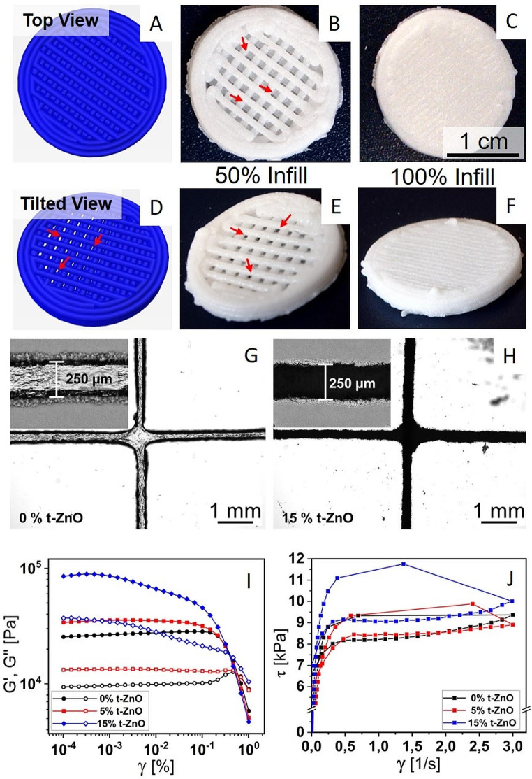 Figure 1
Peer Reviews
No public reviews on file for this paper yet. If you reviewed it on a platform where reviews are public (OpenReview, ICLR, NeurIPS, ICML), you can paste yours below so the community can read it here.
Videos
No videos yet. Explain this paper in a talk, walkthrough, or lecture? Add one.
Taxonomy
TopicsWound Healing and Treatments · Electrospun Nanofibers in Biomedical Applications
Correction to: Nano Convergence (2024) 10:53.
10.1186/s40580-023-00401-6.
Following publication of the original article [1], the author identified an error in Fig. 3. The scale bar value should be “1 cm” instead of “1 mm” in panel C of the figure. The revised Fig. 3 has given below.
Fig. 3. Bioprinting of the alginate-based inks. A–F Simulated and printed constructs. The pattern is picked in a way that no contaminants can enter from the top in a direct way. Still, open porosity, yet no direct path is implemented for the 50% filled constructs to retain oxygen permeability. A and D depict the simulated constructs generated in the slicing software from the respective G-Code. A represents the top view, where no direct path through the construct can be perceived. D shows the same constructs at a tilted angle where the open structure can be observed. B and E show the final printed constructs at a filling factor of 50% in the same viewing angles as A and D, showing both the blocked and the open pathways as stated before. C and F show the constructs with complete filling of 100%, with no easy pathways for oxygen or contaminants. G and H are optical micrographs depicting two crossing lines of printed alginate-based ink with 0% and 15% t-ZnO loading, respectively. The insets show a magnification of an individual line. The more jagged contour of the lines in H are caused by protruding t-ZnO arms. I: Graphs of an amplitude sweep for alginate-based inks with 0% to 15% t-ZnO. The moduli increase with the content of t-ZnO. J: Flow curves of alginate-based inks with 0% to 15% t-ZnO. Both static and dynamic yield stress do not change from 0 to 5% t-ZnO content. A significant increase in static and dynamic yield stress can be seen for 15% t-ZnO
The original article has been corrected.