An Improved Method to Compute the Mutual Capacitance between Interdigital Transducers in Radio Frequency Surface Acoustic Wave Filters
Yali Zou, Xinyu Yang, Ping Luo, Yuhao Liu

TL;DR
This paper introduces a faster and more accurate method to calculate capacitance in radio frequency filters, improving design efficiency.
Contribution
The novel approach combines boundary element and partial capacitance methods to enhance the COM model for SAW filters.
Findings
The proposed method matches commercial software accuracy but calculates faster.
It enables precise electrical response prediction for dual-mode SAW filters.
The method can be integrated into filter design optimization processes.
Abstract
This paper proposes an improved method to calculate the mutual capacitance between interdigital transducer (IDT) electrodes to enhance the accuracy of the traditional coupling-of-modes (COM) model, which is commonly used to simulate surface acoustic wave (SAW) filters and duplexers. In this method, the boundary element method (BEM) is adopted to obtain the capacitance per unit length in a layered medium, while the partial capacitance (PC) method is used to derive the effective relative permittivity of the multi-layered IDT. Numerical results from commercially available software are provided for comparison with the results calculated using the proposed method. The consistent results verify the validity and accuracy of this method, which also demonstrates significantly faster calculation speed compared to commercially available software. Precise electrical response prediction of a…
Genes, proteins, chemicals, diseases, species, mutations and cell lines named across the full text — each resolved to its canonical identifier and authoritative record.
Click any figure to enlarge with its caption.
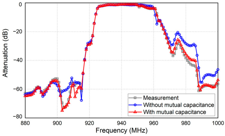 Figure 1
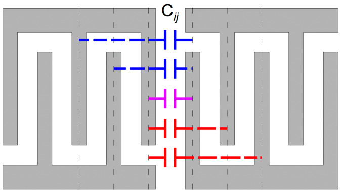 Figure 2
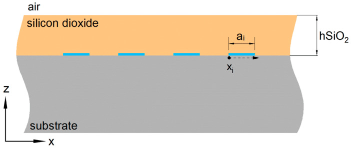 Figure 3
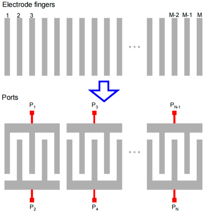 Figure 4
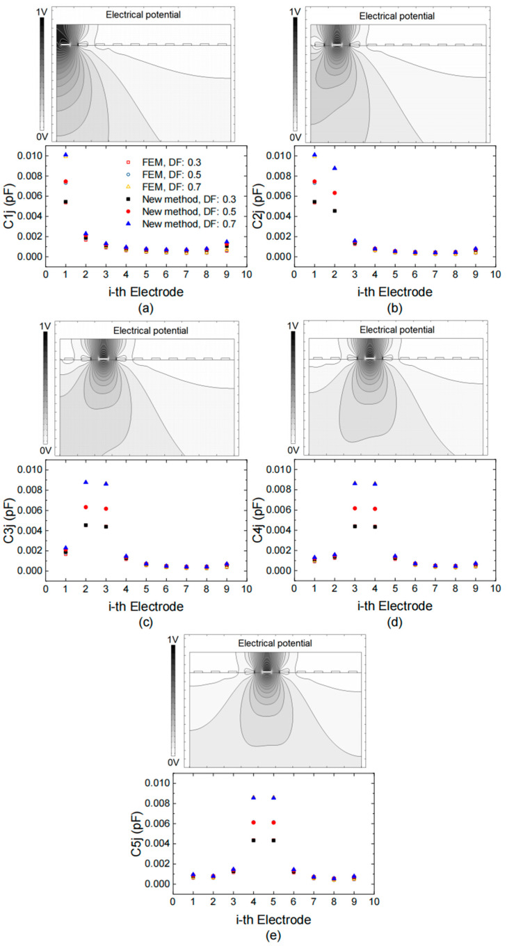 Figure 5
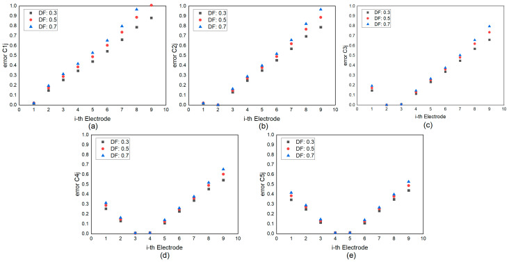 Figure 6
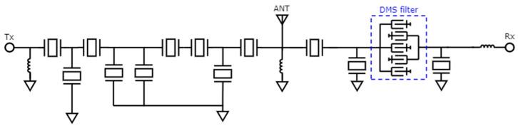 Figure 7
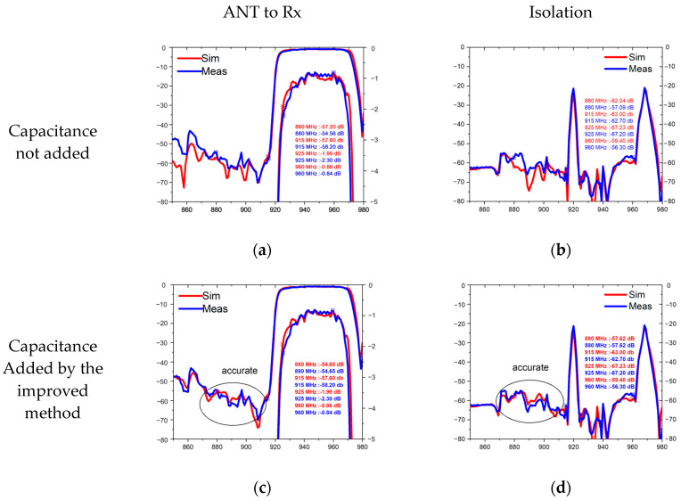 Figure 8
Peer Reviews
No public reviews on file for this paper yet. If you reviewed it on a platform where reviews are public (OpenReview, ICLR, NeurIPS, ICML), you can paste yours below so the community can read it here.
Videos
No videos yet. Explain this paper in a talk, walkthrough, or lecture? Add one.
Taxonomy
TopicsAcoustic Wave Resonator Technologies · Microwave Engineering and Waveguides · Ultrasonics and Acoustic Wave Propagation
1. Introduction
SAW filters, known for their compact size and superior out-of-band rejection capabilities, are extensively utilized in the radio frequency front-ends (RFFE) of mobile communication systems. Although SAW devices exhibit exceptional performance in mobile communications, there is an increasing need to enhance the resonance quality factor further [1]. The typical configurations of SAW filter circuits encompass ladder-type circuits, DMS (dual-mode SAW) type circuits, and hybrid ladder and DMS type circuits. DMS filter circuits are distinguished by their low insertion loss, compact chip size, and excellent out-of-band suppression. When compared to ladder-type filter circuits, which occupy a larger area but offer higher input power tolerance, DMS type filter circuits are typically preferred for applications in the receive path of a duplexer or a single receive band filter. DMS filter circuits often exhibit clean dual-mode resonances along with multiple out-of-band resonances, which can manifest as unwanted spurious modes within the rejection band. To ensure successful duplexer design, these unwanted spurious modes must be accurately captured by the simulation model and subsequently optimized out during the duplexer simulation iterations. Consequently, the precision of the DMS circuit model and the speed of calculation are of paramount importance for the design of the filter.
Accurate and efficient modeling of surface acoustic wave (SAW) resonators is indispensable for the design and optimization of high-performance SAW filters [2,3,4]. A plethora of models have been proposed to facilitate the analysis of SAW devices, often by simplifying the intricate physical aspects of these devices. These models encompass the impulse model [5], equivalent circuit models [6], the coupling-of-modes (COM) model [7], the P-matrix model [8], and the scattering matrix approach [9]. In addition to these models, finite element methods (FEMs) [10,11] and boundary element methods (BEMs) [12,13,14] are also extensively employed for the analysis of SAW devices.
The finite element method (FEM) offers unique advantages in simulations, including its capability to model spurious modes [15], nonlinear effects [16], and SAW devices with complex geometries [17]. Conversely, BEM provides an exact solution for the system and offers several efficiency advantages through direct full-wave analysis based on the fundamental wave equation and boundary conditions. In hybrid FEM/BEM simulations [18,19], FEM is typically employed to simulate arbitrarily shaped finger electrodes, while BEM is utilized to simulate the semi-infinite piezoelectric substrate. This combined approach leverages the strengths of both methods, ensuring a comprehensive and accurate analysis of SAW device behavior.
The coupling-of-modes (COM) model is the most widely utilized approach for computing the electrical response of SAW filters, as it strikes an optimal balance between calculation speed and accuracy. However, the standard COM model primarily focuses on discrete interdigital transducer (IDT) sections and does not fully account for the mutual capacitive coupling between IDTs. This limitation can result in an inaccurate representation of the out-of-band electrical response.
As illustrated in Figure 1, the mutual capacitance has a significant impact on the out-of-band attenuation performance, particularly in the lower side rejection of a dual-mode SAW (DMS) filter. To enhance the precision of the COM model in such scenarios, it is crucial to refine the model to include these previously overlooked mutual capacitance effects.
To enhance the accuracy of the model, one viable solution is to incorporate the mutual capacitance between IDT electrodes across different acoustic tracks within the COM model. Typically, lumped capacitors are added between IDTs to simulate the effects of mutual capacitance. However, the values of these lumped capacitors often need to be determined through experimental data, which can be labor-intensive and may not provide a complete theoretical understanding.
An alternative approach involves utilizing the finite element method (FEM), which is generally acknowledged as the most authentic simulation technique, to calculate mutual capacitance. While this method can yield accurate results, it is computationally intensive and may not be practical for implementation in filter optimization processes due to the significant time required for calculations.
Therefore, this study presents a novel approach that employs the boundary element method (BEM) and the partial capacitance (PC) method to enable rapid and accurate prediction of mutual capacitance. For validation, the mutual capacitance between a periodic IDT with ten finger electrodes, fabricated on a 128°YX-cut LiNbO_3_ substrate, is calculated using both the proposed method and FEM. The results from the two techniques are then compared and discussed. Furthermore, by integrating the COM model, the researchers have designed a high-performance, temperature-compensated SAW (TC-SAW) duplexer. This duplexer incorporates a DMS filter in the receive path, achieving precise out-of-band rejection and isolation.
2. Materials and Methods
Building on the introduction, the researchers conduct a comprehensive analysis and calculation of the mutual capacitance between IDTs in the structure of DMS-type filters. In the conventional COM model, only the capacitance between adjacent electrodes of two neighboring IDT tracks is considered, as depicted by the solid line capacitors in Figure 2. For more complex duplexer designs that require higher precision, it is necessary to consider the capacitance between electrodes that are further apart, as indicated by the dashed line capacitors in Figure 2. Incorporating these additional capacitance elements is essential for improving the model’s accuracy in predicting duplexer isolation, which is typically expected to be in the range of −60 to −70 dB.
As a case study, we focus on the basic DMS structure of a TC-SAW device, using LiNbO_3_ as the substrate. The cross-section of a periodic IDT with two dielectric layers above the electrode layer is shown in Figure 3. Relative permittivity of each dielectric layer is denoted as and , respectively. The first dielectric adjacent to the electrodes has a finite thickness. The thickness of the second dielectric referring to air in our case is infinite. The electrodes of IDT have an aperture of and a width of for the i-th electrode. And indicates the relative x position from the left side of i-th electrode.
The following proposed method in this study is based on three fundamental assumptions: (1) that the electrode thickness is significantly smaller than both the aperture and the electrode width, allowing the electrodes to be treated as sheet conductors in the calculation; (2) that the substrate thickness is generally much larger than the overlying layers, and is therefore considered infinite for the purposes of this analysis; and (3) that the dielectric layer length in the x-direction is assumed to be infinite, a common approximation in the analysis of periodic structures.
2.1. Capacitance Matrix of Finger Electrodes
The boundary element method (BEM) has gained widespread adoption for modeling SAW devices. By employing orthogonal function expansions on electrodes, BEM achieves accurate calculations at the electrode edges. Building upon this foundation, this paper introduces an improved method based on BEM for computing the mutual capacitance between electrodes of neighboring IDTs with a high degree of accuracy and in significantly less time than traditional FEM analyses. To address the singularity at the edges of the electrodes, the proposed method utilizes BEM with weighted Chebyshev polynomials of the first kind as the expansion functions [20]. The upper limit of the order of Chebyshev polynomials, described as , is an integer greater than zero. With increasing value, the calculating results associated with electrical charges are becoming more accurate.
Considering the singularity on both edges of electrodes, the first kind Chebyshev polynomials weighted by a reciprocal of the square root are used as basic functions. Surface charge distribution on the i-th electrode can then be written as the following series expansion functions:
where , is the j-th order Chebyshev polynomials of the first kind, is the center of the i-th electrode, and are undetermined coefficients. The charge distribution on each electrode will only be determined if coefficients are derived.
The electrical potential of infinite periodic IDT is described as an integration of charge distribution:
where is the Green’s function, which has been given in [20]. Substituting Equation (1) into Equation (2), the electrical potential distribution in the -axis is then given as follows:
where is the total number of IDT electrodes. The charge distributions are solved from Equations (1) and (3) by giving for discrete sampling points on electrodes. For simplification, we specify as an even number. If , suggested x coordinates of the sampling points within each electrode are list in Table 1. becomes more accurate with larger order of Chebyshev polynomials. The total charge of i-th electrode is computed by integration over width according to the following expression:
When a specific voltage is applied to only one electrode and all other electrodes are grounded, the capacitance related to this electrode can be determined by measuring the charges. Taking as the voltage applied to each electrode, capacitance per unit length in vacuum, , is obtained by the following simultaneous linear equations, in matrix form:
Considering the multi-layered substrate and aperture of IDT, final capacitance matrix is obtained:
where is the relative effective permittivity for multi-layered dielectrics above and below the electrodes.
2.2. Relative Effective Permittivity
The partial capacitance (PC) method, initially proposed by Kochanov [21], offers an alternative. It was originally applied to coplanar waveguides on substrates with finite thickness. When combined with the conformal mapping technique, the PC method has been utilized to model interdigital capacitors with multi-layered structures [22,23]. Although conformal mapping can deliver precise results, it is often constrained by the complexity of the model’s geometry, which can make it challenging to apply in practical design scenarios. The partial capacitance (PC) method is applied to the calculation of mutual interdigital capacitors on multi-layered substrates [24].
The relative permittivity above electrodes is computed from lower to upper dielectric iterative by applying Green’s function [25]. In our case, has a height of :
For a hexagonal piezoelectric material below electrodes, the relative permittivity is given by the following [26]:
where and are the principal dielectric constant, and the superscript indicates that the permittivities are measured under the zero-stress condition. Under the low-frequency approximation, the relative effective permittivity is simply given as parallel connection by the following:
2.3. Mutual Capacitance of DMS Filters
In this case, the measured capacitance matrix is defined as the Maxwell capacitance, which is, however, not convenient to implement in a typical circuit simulator. A mutual capacitance matrix form between discrete electrodes is used instead:
where in the matrix stands for mutual capacitance elements.
As shown in Figure 4, when a practical DMS filter is simulated, periodic finger electrodes are classified into an even number of groups according to IDT ports. Finger electrodes with the same port are paralleled connected, resulting in the same electrical potential, which indicates zero capacitance within the same port. As a result, the dimension of the capacitance matrix obtained from BEM is reduced from to for N-port DMS filter simulation. The diagonal elements in the matrix are self-capacitance, and capacitance between the facing ports needs to be set to zero due to the intrinsic value form COM model. The capacitance matrix of the IDT ports is convenient to integrate into a circuit simulator once it is computed.
By integrating this advanced approach into the conventional COM model, a mutual capacitance matrix is introduced, resulting in a modified model that can accurately predict the out-of-band electrical responses of dual-mode SAW (DMS) filters.
3. Results and Discussion
3.1. Simulation of One Pair of IDTs
Building on the analysis presented in the previous section, the capacitance between the electrodes of a multi-layered dielectric IDT was computed. The results were subsequently compared with those obtained from a commercial finite element method (FEM) solver. The periodic IDT electrode pitch was set at 2 μm with varying duty factors (DF) of 0.3, 0.5, and 0.7, respectively. A 1.2 μm thick layer of SiO_2_ was deposited on a 128°YX-cut lithium niobate (LiNbO_3_) piezoelectric substrate to serve as a temperature compensation layer, enveloping the electrodes. The number of finger electrodes is 10, denoted as . To enhance the accuracy of the results, the order of the Chebyshev polynomials, , was set to 2, indicating that three discrete sampling points along each electrode were required in the calculation. Simulation parameters are summarized in Table 2. This results in a matrix being solved by the proposed method.
The mutual capacitance for 10 finger electrodes was calculated using both our modified method and a commercial finite element method (FEM) solver. Due to the symmetric conformation, only half of the capacitance is shown in Figure 5. Figure 5a–e illustrate the electrical potential distribution within the stack and provide a comparison of the capacitance values obtained from the two methods, respectively. The capacitance computed by the modified method closely aligns with the results from the commercial FEM solver, with slightly greater differences at the edges compared to the center due to fringing effects accounted for in the FEM simulation. The error associated with the current method was assessed [27,28]. For a given value, the error increases monotonically as the spacing between fingers increases. A value less than 0.5 appears to be reasonable when modeling TC-SAW IDTs, considering the capacitance magnitude is on the order of , which minimally impacts filter performance. Figure 6 illustrates the estimated error in capacitance related to the i-th electrode, providing guidance that mutual capacitance beyond five adjacent fingers can be disregarded in the simulation of TC-SAW DMS filters.
The FEM solver required 41 s to compute a capacitance matrix using a server equipped with 52 cores and 104 threads. In contrast, the proposed method achieved the same computation in just 0.62 s for the same structure, representing a remarkable 98.5% reduction in simulation time compared to FEM. Relative to the FEM, this substantial enhancement in simulation efficiency allows for a higher iteration frequency during the design process of filters and significantly reduces the time cost associated with filter optimization. Consequently, the proposed method offers the potential to achieve precise design and optimization of dual-mode SAW (DMS) filters, facilitating more efficient and effective filter development.
3.2. Design of a TC-SAW Duplexer
To confirm the efficacy of the proposed method, it was integrated into the conventional COM model and utilized to design and optimize a 5G New Radio (NR) Band VIII TC-SAW duplexer. Figure 7 shows the topology of the Band VIII duplexer, where the transmitting (Tx) filter is a pure ladder-type filter, while the receiving (Rx) filter is composed of resonators as well as a DMS. The inclusion of the DMS filter in the Rx filter is essential due to its superior out-of-band rejection and isolation, particularly on the lower side of frequency responses [29,30,31]. The NR Band VIII duplexer was fabricated using a high-Q TC-SAW process in Changzhou ChemSemi Corporation (Changzhou, China) [32]. Figure 8 presents a comparative analysis of the simulation and experimental results for the NR Band VIII duplexer, with the red line indicating the simulation outcomes and the blue line representing the measured data. Figure 8a,c depict the S21 transmission loss from the antenna to the Rx, while Figure 8b,d illustrate the duplexer’s isolation performance.
Comparing the simulated and measured results, both with and without accounting for mutual capacitance, reveals that the proposed method yields a superior fit between simulation and experimental outcomes, particularly in the prediction of critical isolation performance. This underscores the importance of accurate models. In the practical design of a duplexer, the IDTs of DMS filters in the Rx path are unlikely to achieve perfectly periodic conditions. Particularly in the regions near the adjacent IDT fingers, the pitch often undergoes substantial variations [33]. With this improved model, the effects of non-periodic IDT pitch can be more rapidly and accurately captured by adjusting the derived parameters and .
Table 3 provides a comparative analysis of the present method against two other techniques, highlighting the distinct characteristics and performance of each method. According to the table, all three methods are capable of meeting the accuracy requirements for the SAW model. The finite element method (FEM) is notable for its high accuracy but is also characterized by its extremely slow computation speed. Conversely, the conformal mapping method, while offering a certain level of accuracy, is more complex in its implementation. The method proposed in this paper stands out for its ability to maintain sufficient accuracy without increasing the complexity of the model and for its significant improvement in computational speed. This efficiency places the proposed method ahead of the other techniques in terms of overall performance, offering a superior approach for the design and optimization of SAW filters and duplexers.
4. Conclusions
This work presents an effective method that combines the BEM and the PC methods to obtain the mutual capacitance matrix of IDT electrodes with multi-layered dielectrics. The mutual capacitance of ten periodic IDT electrodes was computed using the proposed method, and the results were found to be in good agreement with those calculated from a commercial FEM solver. The application of this method enables the precise prediction of the out-of-band rejection of DMS filters while significantly reducing the computation time required. This enhanced efficiency allows for the seamless integration of the proposed method into the filter optimization process. The ability to accurately model the mutual capacitance between IDT electrodes is crucial for the design of high-performance SAW and TC-SAW filters, particularly those incorporating DMS structures, targeting 5G New Radio applications.
The reference list from the paper itself. Each links out to its DOI / PubMed record.
- 1Wu J. Zhang S. Zhang L. Zhou H. Zheng P. Yao H. Li Z. Huang K. Wu T. Ou X. Exploring Low-Loss Surface Acoustic Wave Devices on Heterogeneous Substrates IEEE Trans. Ultrason. Ferroelectr. Freq. Control 2022692579258410.1109/TUFFC.2022.317969935653448 · doi ↗ · pubmed ↗
- 2Hagelauer A. Fattinger G. Ruppel C.C.W. Ueda M. Hashimoto K.-Y. Tag A. Microwave acoustic wave devices: Recent advances on architectures, modeling, materials, and packaging IEEE Trans. Microw. Theory Tech.2018664548456210.1109/TMTT.2018.2854160 · doi ↗
- 3Nakamura H. Komatsu T. Nakanishi H. Tsurunari T. Fujiwara J. Reduction of transverse leakage for SAW resonators on Li Ta O 3 substrate Proceedings of the IEEE International Ultrasonics Symposium 2012 Dublin, Ireland 7–10 October 20121248125110.1109/ULTSYM.2012.0311 · doi ↗
- 4Wu Z. Liu Y.-M. Shi B. Bao J.-F. Hashimoto K.-Y. COM-based modeling of saw scattering at reflector outer edges in IHP SAW resonator Proceedings of the IEEE International Ultrasonics Symposium 2022 Venice, Italy 10–13 October 20221410.1109/IUS 54386.2022.9958143 · doi ↗
- 5Hartmann C.S. Bell D.T. Rosenfeld R.C. Impulse model design of acoustic surface-wave filters IEEE Trans. Microw. Theory Tech.19732116217510.1109/TMTT.1973.1127967 · doi ↗
- 6Hoang T. Beghi M.G. SAW parameters analysis and equivalent circuit of SAW device Acoust. Waves-Microdevices Helioseismology 201144348310.5772/19910 · doi ↗
- 7Plessky V. Koskela J. Coupling-of-modes analysis of SAW devices Int. J. High Speed Electron. Syst.20001086794710.1142/S 0129156400000684 · doi ↗
- 8Kanouni F. Amara S. Assali A. Arab F. Qin Z. A P-matrix-based model for the frequency analysis of IDT/Al Sc N/Sapphire SAW-delay line Sens. Actuators A Phys.202030711198010.1016/j.sna.2020.111980 · doi ↗