Macroscopic Biaxial Order in Multilayer Films of Bent-Core Liquid Crystals Deposited by Combined Langmuir–Blodgett/Langmuir–Schaefer Technique
Francesco Vita, Fabrizio Corrado Adamo, Mario Campana, Blake Bordokas, Federica Ciuchi, Maria Penelope De Santo, Daniel Hermida-Merino, Angela Lisovsky, Michela Pisani, Diego Pontoni, Eric Scharrer, Oriano Francescangeli

TL;DR
Researchers showed that bent-core liquid crystals can form ordered structures in multilayer films, which could help in understanding and controlling their unique properties.
Contribution
Demonstration of macroscopic biaxial order in bent-core liquid crystal films using a combined deposition technique.
Findings
Multilayer films of bent-core nematic exhibit macroscopic in-plane ordering.
Long molecular axis tilts relative to the surface, and the short axis aligns with the compression direction.
Combined Langmuir–Blodgett/Langmuir–Schaefer technique enables controlled ordering.
Abstract
Bent-core liquid crystals, a class of mesogenic compounds with non-linear molecular structures, are well known for their unconventional mesophases, characterized by complex molecular (and supramolecular) ordering and often featuring biaxial and polar properties. In the nematic phase, their unique behavior is manifested in the formation of nano-sized biaxial clusters of layered molecules (cybotactic groups). While this prompted their consideration in the quest for nematic biaxiality, experimental evidence indicates that the cybotactic order is only short-ranged and that the nematic phase is macroscopically uniaxial. By combining atomic force microscopy, neutron reflectivity and wide-angle grazing-incidence X-ray scattering, here, we demonstrate that multilayer films of a bent-core nematic, deposited on silicon by a combined Langmuir–Blodgett and Langmuir–Schaefer approach, exhibit…
Click any figure to enlarge with its caption.
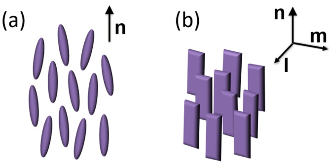 Figure 1
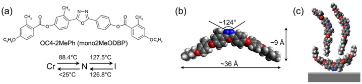 Figure 2
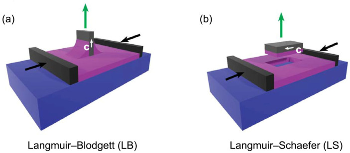 Figure 3
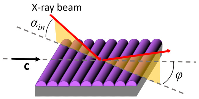 Figure 4
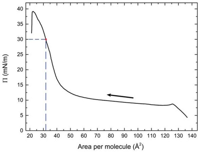 Figure 5
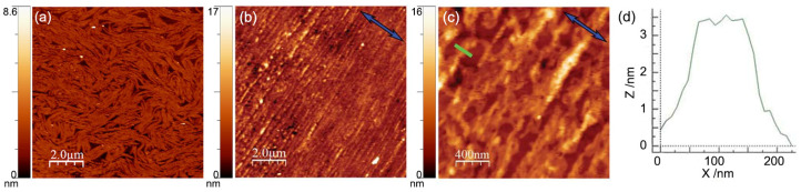 Figure 6
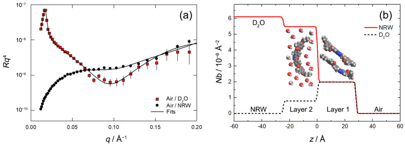 Figure 7
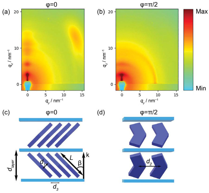 Figure 8
- —National Science Foundation
Peer Reviews
No public reviews on file for this paper yet. If you reviewed it on a platform where reviews are public (OpenReview, ICLR, NeurIPS, ICML), you can paste yours below so the community can read it here.
Videos
No videos yet. Explain this paper in a talk, walkthrough, or lecture? Add one.
Taxonomy
TopicsLiquid Crystal Research Advancements · Advanced Materials and Mechanics · Lipid Membrane Structure and Behavior
1. Introduction
Among the several different mesophases formed by liquid crystalline materials, the nematic (N) phase of calamitic (i.e., rod-like) liquid crystals (LCs) is by far the most well known, as it provides the basis for the widespread LC display technology. Its fundamental feature is the spontaneous alignment of the molecules’ long axes along a common average direction, denoted by the molecular director n (Figure 1a). As a consequence, all the physical properties of a N material are strongly anisotropic, with characteristic uniaxial symmetry.
For the N phase to be of any practical utility, it is necessary to control the orientation of the n director over macroscopic distances. In typical LC devices, this task is accomplished by imposing anisotropic surface anchoring conditions at the confining boundaries, which forces n to align along a predetermined preferential direction; once the ground state orientation of n has been established, it can then be switched through the torque exerted by an external electric field.
Actually, theoretical considerations do not forbid the possibility of a biaxial N phase, where the average orientation of the long molecular axis along n is accompanied by the preferential alignment of a molecular transverse axis along a secondary director m orthogonal to n (Figure 1b) [1,2]. However, despite considerable experimental effort, the biaxial N phase has remained elusive, with no undisputable evidence reported until now for low-molecular-weight calamitic LCs [3,4]. Over the last two decades, bent-core mesogens (BCMs), a class of compounds featuring a kinked aromatic core between two terminal aliphatic tails, have attracted considerable interest for the formation of a variety of exotic mesophases and self-assembled supramolecular structures [5,6,7,8], as well as for the exhibition of a possibly biaxial N phase [5,9,10,11]. Although the occurrence of spontaneous macroscopic biaxiality in nematic BCMs has been questioned, strong experimental evidence suggests the presence of local biaxial (and possibly polar) order within nanosized clusters of stratified molecules (known as cybotactic groups) which permeate the N phase. While the clusters’ transverse axes are randomly oriented in the unperturbed N phase, resulting in an overall uniaxial mesophase, proper external stimuli can align the clusters, extending biaxial (and possibly polar) order over a macroscopic length scale [9,10,11,12,13,14].
A critical issue for the experimental study of BCMs, as well as for their use in electro-optical devices, is the capability to finely control the orientation of the molecular director by means of proper anchoring conditions. Unfortunately, the surface treatments known to be effective for aligning conventional nematics often provide unexpected results when used with BCMs [15,16,17]. Notably, this ambiguity in the alignment of BCMs has resulted in conflicting interpretations of several experiments, e.g., with claims of N biaxiality being reinterpreted in terms of anchoring transitions in a uniaxial N phase [18,19,20]. Clearly, the experimental demonstration of N biaxiality in any LC system would be extremely eased by the ability to align both n and m directors by means of biaxial anchoring conditions.
An unconventional strategy to tackle the BCM alignment problem is the deposition of BCM Langmuir films: mesogens spread over water form a thin layer at the water–air interface, with molecular packing controlled by the pressure exerted on the film by a movable barrier; once the desired molecular arrangement has been obtained, the film can be transferred onto a solid substrate. This technique, already used to deposit rod-like materials of different natures like cellulose nanocrystals [21] or carbon nanotubes [22], represents a valuable tool to determine the surface alignment of BCMs and to study their anchoring properties. The resulting films are of interest by themselves, e.g., in the case of ferroelectric LCs, or they can be used as aligning substrates for bulk LCs [23,24,25,26,27,28,29,30,31,32,33,34,35,36,37,38].
Recently, we have used this approach to deposit thin films of a BCM known as OC4-2MePh(mono2MeODBP) [38]. It belongs to a widely studied family of laterally methylated BCMs featuring an oxadiazole bisphenol core and short butoxy terminal chains (Figure 2a,b) [39,40,41,42]. The N phase of these mesogens exhibits a few peculiarities: the possibility to be supercooled to room temperature and the strong evidence (from X-ray diffraction data) of locally biaxial molecular ordering [40,41,42]. The formation of stable Langmuir films in these BCMs is remarkable, as their chemical structure, with two hydrophobic tails and a more hydrophilic core, is significantly different from that of typical amphiphilic molecules. In fact, the complex BCM interaction with the water sub-phase in Langmuir films is responsible for the unusual bilayer structure of deposited films revealed by X-ray reflectivity (XRR) measurements: an upper layer of upright molecules and a bottom layer of flat molecules (Figure 2c) [38].
While XRR can elucidate the film structure in the direction orthogonal to the substrate, it is blind to in-plane order. The latter can be conveniently investigated by means of grazing-incidence wide-angle X-ray scattering (GIWAXS). Unfortunately, because of their chemical structure (lacking heavy atoms) and short-range positional order, LCs exhibit weak and diffuse diffraction features. As a result, films obtained with a single deposition are too thin to generate a detectable diffraction signal. To address this problem, here, we describe the preparation of multilayer samples via repeated Langmuir–Blodgett (LB)/Langmuir–Schaefer (LS) deposition. GIWAXS measurements performed on these samples reveal a tilted, smectic-C like, molecular stratification and macroscopic in-plane ordering; the films are thus biaxial. The structure of deposited films is compared with that of Langmuir films over water, investigated by means of neutron reflectivity (NR). The results provide further insight into the BCM assembly at the air–water interface, showing that molecular ordering is substantially preserved during the deposition process.
2. Materials and Methods
2.1. Mesogen Synthesis
The synthesis of OC4-2MePh(mono2MeODBP) has been described elsewhere [39]. Its chemical structure, typical dimensions in the fully extended configuration and mesophase diagram are shown in Figure 2a,b.
2.2. Sample Preparation
Langmuir films of OC4-2MePh(mono2MeODBP) over water were prepared in a NIMA Langmuir–Pockels trough equipped with control barriers (NIMA Technology Ltd., Coventry, UK). A 0.1 mg/mL solution of OC4-2MePh(mono2MeODBP) in chloroform was spread over pure water (resistivity of 18.2 MΩ/cm); the latter was obtained from an ELGA PURELAB Flex water purification system (ELGA LabWater, Wycombe, UK). After the evaporation of the solvent, the film was compressed by closing the control barriers at a constant rate of 70 cm^2^/min from an initial area per molecule of A ≈ 130 Å^2^. Compression isotherms (surface pressure Π vs. area per molecule APM) were measured using a Wilhelmy plate pressure sensor.
Multilayer samples were obtained by repeated film depositions on silicon substrates ((111)-cut p-doped), previously treated with piranha solution. Using (111)-cut silicon prevented the appearance of Bragg reflections in the q-range of interest for GIWAXS experiments. The deposition pressure was set at Π = 30 mN/m, corresponding to an area per molecule of APM ≈ 32 Å^2^. The deposition of the first layer was performed with the LB technique, i.e., by extraction of a vertical substrate immersed in the water before the formation of the Langmuir film (Figure 3a). Subsequently, 28 additional layers (for a total of 29 layers) were deposited using the LS configuration (Figure 3b): in this case, the substrate, kept parallel to the water surface, was gently lowered until it came in contact with the Langmuir film, which was hence transferred onto the silicon. In the LS depositions, the substrate orientation was chosen in such a way that the barrier compression direction was parallel to the substrate extraction direction of the first LB deposition. We denote this direction by the in-plane vector c. After each layer deposition, the samples were thoroughly dried by a nitrogen flux.
2.3. Atomic Force Microscopy Measurements
Samples obtained by a single LB deposition on silicon were investigated by atomic force microscopy (AFM) using a Multimode 8 AFM microscope equipped with a Nanoscope V controller (Bruker, Santa Barbara, CA, USA). Data were acquired in tapping mode using silicon cantilevers (model TAP150, Bruker, Santa Barbara, CA, USA).
2.4. Neutron Reflectivity Measurements
NR measurements on Langmuir films were performed at the Surf beamline of ISIS Neutron and Muon Source (Rutherford Appleton Laboratory, Didcot, United Kingdom) [43] using a polychromatic neutron beam with wavelength λ between 0.5 and 7 Å. Measurements were performed at three different angles (θ = 0.35°, 0.65° and 1.5°) to cover a suitable q range ( ).
Measurements were performed in two different contrasts (sub-phases) to ensure maximum sensitivity to the layer adsorbed at the interface. While the use of null-reflecting water (NRW) is particularly sensitive to the adsorbed amount at the interface, the use of D_2_O enables the resolution of the interfacial structure.
Langmuir films of OC4-2MePh(mono2MeODBP) were prepared using a NIMA trough with an area of 20 × 30 cm^2^ (NIMA Technology Ltd., Coventry, UK). A 0.1 mg/mL solution of OC4-2MePh(mono2MeODBP) in chloroform was spread on each sub-phase. Measurements were taken at a fixed surface pressure of 30 mN/m. The compression isotherms measured in this condition did not significantly differ from those measured during the previously described sample preparation experiments. In particular, the area per molecule calculated from the trough area at 30 mN/m was ~36 Å^2^, very close to the value of ~32 Å^2^ measured in deposition experiments.
The two contrasts were co-fitted using the in-house built software Rascal (version 2019), which employs the Abeles matrix formalism to calculate the neutron reflectivity from stratified media [44]. A Bayesian analysis of the fit was then used to associate an appropriate confidence interval to the optimal fitted values. The reflectivity profiles were co-fitted, modeling the air–water interface as a finite stack of layers, with each layer being characterized by a thickness t, an interlayer roughness σ and a scattering length density Nb_layer_. The scattering length density of a layer is as follows:
where N_i_ and b_i_ are the number density and the scattering length for the i-th species present in the layer, respectively. The latter can be calculated from composition for the BCM, D_2_O and H_2_O: b_BCM_ = 169 fm molec^−1^, b_D2O_ = 19.1 fm molec^−1^ and b_H2O_ = −1.67 fm molec^−1^ (note how mixing ~8% of D_2_O and 92% of H_2_O leads to NRW with b_NRW_ = 0). D_2_O often presents some H_2_O contamination, and its Nb may be lower than the theoretical value of 6.35 × 10^−6^ Å^−2^. The D_2_O used in this study had an Nb = 6.21 × 10^−6^ Å^−2^, as calculated from the observed critical edge q_c_ ( , where ΔNb is the difference in Nb between the two bulk phases, air and D_2_O).
When using NRW, the reflectivity is solely originating from the interfacial monolayer. Under these conditions, the adsorbed amount per unit area Γ and the corresponding area per molecule APM can be calculated from the experimentally determined parameters Nb_layer_ and t as follows:
where N_A_ is Avogadro’s number [45]. The APM is then calculated as follows:
The fitting of the experimental data, performed via scripting in Rascal, used the thickness t, the APM and, where applicable, the percentage of hydration water as fitting parameters for each layer. No roughness was required to fit the reflectivity data. We set the interlayer roughness at 0.5 Å in order to obtain smoother transitions in the Nb profiles, hence a better visualization of the plots.
2.5. Grazing-Incidence Wide-Angle X-ray Scattering Measurements
The in-plane and out-of-plane order of multilayer films on silicon was investigated by GIWAXS. The measurements were carried out at the BM26B-Dubble beamline of the European Synchrotron Radiation Facility (ESRF, Grenoble, France) and at the NCD-SWEET beamline of the ALBA synchrotron (Barcelona, Spain). The data here reported were collected under the following experimental conditions: the samples were mounted on a rotating stage allowing measurements under different azimuthal orientations (the φ angle between the beam incidence plane and the film compression direction c, as shown in Figure 4); the beam energy was 8.00 keV (wavelength λ = 1.55 Å) and the beam size was 111 × 12 μm^2^ (width × height); the sample-to-detector distance was D = 198 mm and the fixed incident angle was set at α_in_ = 0.16°, leading to an irradiated area on the sample of ~0.5 mm^2^; all the patterns were recorded at room temperature, with an exposure time of 30 s, using an LX255-HS detector (Rayonix, Evanston, IL, USA).
3. Results and Discussion
3.1. Preliminary Langmuir Film Characterization
A typical compression isotherm of OC4-2MePh(mono2MeODBP) over water is shown in Figure 5. The sudden pressure drop at the end of the compression curve indicates the collapse of the film occurring at Π ≈ 39 mN/m. Below this threshold, the isotherm is characterized by a plateau at the pressure of ~10 mN/m, during which, the area per molecule decreases from ~120 to ~60 Å^2^ with only a minimal increase in the surface pressure, followed by a steep increase in the pressure. In our previous work [38], we demonstrated that the plateau is due to the coalescence and internal reorganization of the initially floating monolayer domains, with the final formation of a more stable and uniform double molecular layer in correspondence of the pressure increase. Consequently, in that case, we chose the end of the plateau, at a pressure of 12 mN/m, as the set point for the film deposition. However, the resulting film morphology was still not very homogenous, with AFM images showing the formation of fibrous supramolecular structures locally aligned with each other but without long-range orientational order (Figure 6a).
Aiming to obtain more uniform coverage of the substrate and, above all, more ordered packing of the molecules, for the present work, we chose a higher deposition pressure of 30 mN/m, corresponding to an area per molecule of ~32 Å^2^. To investigate the effect of the large deposition pressure on the film morphology, a single LB deposition on silicon was examined by AFM (Figure 6b–d). The difference with films deposited at Π = 12 mN/m is evident. The film became much more uniform; the fibrous meandering structure present in low-pressure samples was replaced by a dense sequence of parallel grooves, homogenously aligned along the direction perpendicular to the dipping direction c (Figure 6b,c). These undulations had widths of ~100 nm and depths of ~3 nm (Figure 6d), values quite similar to those observed in samples deposited at lower pressure. Clearly, the higher deposition pressure resulted in a more ordered mesoscale structure, characterized by an in-plane anisotropy extending uniformly over the sample surface.
3.2. Neutron Reflectivity Measurements
To further investigate the effect of the increased deposition pressure on the film morphology, NR measurements were performed on the BCM Langmuir film at a fixed pressure of 30 mN/m, representing conditions prior to deposition. Figure 7a shows the reflectivity curves measured on D_2_O and NWR along with the best line fits; the corresponding Nb profiles are shown in Figure 7b together with a molecular model of the interfacial layer. Attempts to fit the reflectivity profiles through a one-layer model proved unsuccessful. Satisfactory results were obtained with the addition of a second layer. The fit results indicate that the upper layer (Layer 1) contains only BCM molecules (no hydration): this is often observed within Langmuir monolayers where the hydrophobic part is expelled out of the aqueous phase and the Van der Waals interactions within the monolayer ensure tight packing. The lower layer (Layer 2) consists of BCM and water and represents a diffuse layer on the aqueous side of the interface. It must be stressed that modeling this diffuse layer on the air side of the interface (i.e., as a layer composed of air and BCM molecules) led to an unsatisfactory fit of the data.
The fitted parameters are summarized in Table 1 with the corresponding 65% confidence intervals. The thickness of the upper layer (27.8 Å) is significantly lower than the extended full length of the molecule (~36 Å) and is consistent with an emerged layer of tilted BCM molecules (Figure 7b). In fact, the measured value is very close to the layer thickness provided by GIWAXS for deposited multilayers (25.1 Å), wherein molecules assume a tilted configuration (as discussed in the next section). The APM within this layer is 30.5 Å^2^, indicating that the BCM molecules are very well-ordered within the monolayer. This small APM value is evidently incompatible with the molecules lying flat. Also, in this case, the APM is very close to the value estimated by GIWAXS for deposited multilayers (33.9 Å^2^; see next section), further supporting the conclusion that the tilted molecular arrangement observed in deposited films is already present in the Langmuir film prior to deposition.
The thickness of the bottom layer is slightly smaller, but it is highly hydrated (77% water in the layer) and contains considerably less material (28% of the overall interfacial BCM content). The latter percentage is similar to the results of previous XRR measurements on deposited films, which revealed a ratio of 1.92: 1 between the number of molecules in the top and in the bottom layer [38]. The larger value of APM for Layer 2 (77.5 Å^2^, quite close to the value of 69.1 Å^2^ obtained from XRR measurements in anhydrous conditions) would suggest an arrangement with the molecules lying flat with lifted terminal tails. However, the high level of hydration and the layer thickness, large for a layer of flat molecules, rather indicate a highly dispersed layer of relatively disordered molecules.
In evaluating the details of the film structure, one should also consider that our two-layer model necessarily provides a simplified picture, as it does not take into account the variation in Nb across the BCM molecules (core vs. tails) and the possibility of a partial layer intermixing (e.g., by tail interdigitation) which would make the boundary between the two layers somewhat ill defined. Actually, the total thickness of the interfacial film is 52.8 Å, a value very close to that of 49 Å obtained by XRR for dry Langmuir films deposited on silicon at a pressure of 12 mN/m [38]. Considering the different deposition pressure and the different content of water, the results of the two techniques are in substantial agreement in describing the system.
3.3. Grazing-Incidence Wide-Angle X-ray Scattering Measurements
The multilayer films deposited on silicon with the combined LB/LS methodology described in Section 2.2 were characterized by GIWAXS with the geometry shown in Figure 4. Typical diffraction patterns measured for φ = 0 (incidence plane parallel to c) and φ = π/2 (incidence plane perpendicular to c) are shown in Figure 8a,b, respectively. The difference between the two diffraction patterns is a clear indication of the sample in-plane anisotropy, already evidenced by the AFM scans. However, while the anisotropy observed by AFM is relative to the mesoscale sample morphology, the GIWAXS data pertain to a much lower length scale, revealing the anisotropy of the molecular ordering.
Looking into the details of the GIWAXS patterns, it is possible to notice a sequence of reflections centered at q_y_ = 0. They consist of a fundamental reflection at q_z_ = 2.51 nm^−^^1^ and the corresponding higher orders. These reflections, present in both patterns, are clearly related to the multilayer nature of the sample and correspond to an interlayer distance d_layer_ = 25.1 Å. This value is significantly lower than the molecular length (L = ~36 Å). Assuming no intercalation, this suggests a tilt of the molecules, with the molecular long axis forming an angle β = cos^−1^(d_layer_/L) = 46° with the layer normal (Figure 8c).
Comparing this sequence of reflections in the two patterns, it can be noticed that they are much more intense and transversally narrow in the pattern taken at φ = 0 (Figure 8a). By contrast, a significant transverse broadening affects the reflections in the patterns taken at φ = π/2 (Figure 8b), which also smears out the diffraction intensity. This effect is attributed the presence of grooves similar to those evidenced by AFM scans for single LB depositions (Figure 6b,d), i.e., to undulations of the layers propagating along the Langmuir film compression direction c, as shown in Figure 4.
Figure 8a also shows a broad oblique reflection in the wide-angle region, approximately centered at (q_y_ ≈ 13.3 nm^−^^1^, q_z_ ≈ 12.7 nm^−^^1^). The same feature is absent in the pattern taken at φ = π/2. The q vector of this reflection forms an angle of ~46° with the layer normal; this value exactly matches the angle β estimated above and corresponds to an intermolecular distance d1 ≈ 3.42 Å, the typical value of the intermolecular distance between stacked aromatic groups. Based on these observations, we attribute the wide-angle reflection to the transverse (face-to-face) positional correlation between close-packed mesogens, tilted with respect to the layer normal, as schematically shown in Figure 8c. As is typical in fluid LC systems, this transverse correlation is very short-ranged, as indicated by the breadth of the corresponding reflection. Finally, the disappearance of this oblique reflection for φ = π/2 indicates that the molecules tilt in the plane orthogonal to the compression direction c. Although the diffraction patterns at φ = 0 (Figure 8a) only show one wide-angle reflection (because of the detector being off-center), a rotation of the sample by π results in the same diffraction pattern. This symmetry implies an equivalent number of molecules tilted to the right and to the left of the c direction. This could be due, for example, to the presence of domains with opposite tilt as well as to layers with alternate tilt directions, as shown in the model of Figure 8c.
For φ = π/2, the wide-angle diffraction feature is substituted by an in-plane peak centered at (q_y_ = 9.12 nm^−^^1^, q_z_ = 0 nm^−^^1^). It corresponds to a d-spacing d2 = 6.89 Å, which can be interpreted as the transverse intermolecular distance measured in the plane of the mesogen cores (Figure 8d). While the transverse broadening of this reflection may be once again attributed to the film undulations, this diffraction feature is rather narrow in the radial direction (along q_y_). This indicates a relatively long-ranged positional order in the plane of the film along the compression direction. The layer area associated with each molecule can be calculated as the product of d2 and (see Figure 8c,d), obtaining a value of 33.9 Å^2^, in excellent agreement with the APM value estimated by NR measurement on the water subphase.
4. Conclusions
The NR measurements performed on Langmuir films substantially confirm the complex nature of BCM assembly over water, with the mesogens organizing in a double molecular layer, most likely to decrease the interaction with water of the hydrophobic terminal chains. The top layer is tightly packed and lies entirely above the water surface, whereas the bottom layer is more diffuse and totally submerged. Transferring the Langmuir film onto a solid substrate via LB deposition preserves this double-layer structure (with the bottom layer assuming a more ordered configuration upon water evaporation), as formerly demonstrated [38]. Here, we showed that subsequent depositions via LS methodology result in biaxial films made of a stack of titled molecules with in-plane anisotropy. The layer thickness and the APM measured in the deposited films are very close to the corresponding values in the top layer of the Langmuir films, indicating that the tilted molecular ordering is already present at the water–air interface and is preserved in the deposition process. Apparently, after the first LB deposition, the more diffuse bottom layer of the Langmuir film does not take part in the subsequent LS depositions and does not affect the final film structure.
A remarkable feature of the deposited films is their in-plane anisotropy: considering the large investigated area in the GIWAXS geometry, it extends homogenously over macroscopic distances. This peculiar arrangement is clearly related to the inherent anisotropy of the sample preparation method, with the compression direction breaking the in-plane symmetry of the Langmuir film. It is interesting to observe that the in-plane anisotropy (and hence the film biaxiality) manifests itself at several levels: on the mesoscale, in the formation of grooves uniformly aligned along the c direction; on the molecular length scale, in the tilt of the long molecular axis in the plane orthogonal to c and in the coherent alignment of the molecular transverse axes (proper biaxiality). The last effect is not entirely new for OC4-2MePh(mono2MeODBP), as well as for other laterally substituted oxadiazole-based compounds, with X-ray diffraction measurements evidencing a strong tendency to biaxial packing in the N phase of this class of mesogens [40,41,42]. However, in the bulk, such ordering averages out over macroscopic distances, resulting in a uniaxial N phase, as proved by a thorough optical investigation [20]. The described deposition technique represents, hence, an effective strategy to extend the peculiar tendency toward local biaxial ordering of this BCM, forcing the mesogens to adopt a uniform organization over a large area.
Finally, it is worth noting that the phase diagram of bulk OC4-2MePh(mono2MeODBP) does not show any smectic mesophase. The tilted stratified structure of our film, resembling a smectic C phase, is thus artificially created by the fabrication method (although it is surprisingly stable, being observed several weeks after the film deposition). The SmC phase of BCMs is interesting as it can feature polar (ferroelectric or antiferroelectric) properties, like in the well-known SmCP (or B_2_) phase, through the coherent alignment of the transverse molecular dipoles (pointed along the apex bisectors) [8,27,28]. In our case, we demonstrated that the molecules are all tilted in the same plane, perpendicular to the film compression direction c, and that the molecular dipoles are perpendicular to this plane, and hence parallel to c (Figure 8c,d). This is remarkable, as it is a prerequisite to exhibit a SmCP-like polarization. However, the polar character of the film could not be definitely proved by our measurements as GIWAXS is unable to distinguish between opposite orientations of the apex bisectors, and hence of the molecular dipoles. This aspect certainly deserves further investigation through electro-optical characterization. Another interesting question to be elucidated is whether the mesoscale undulations observed in our films could be caused by a frustration mechanism similar to that originating saddle splay layer distortion in the so-called helical nanofilament (HNF) phases of BCMs [7,8,46,47].
The reference list from the paper itself. Each links out to its DOI / PubMed record.
- 1Freiser M.J. Ordered states of a nematic liquid Phys. Rev. Lett.1970241041104310.1103/Phys Rev Lett.24.1041 · doi ↗
- 2Luckhurst G.R. Sluckin T.J. Biaxial Nematic Liquid Crystals: Theory, Simulation, and Experiment John Wiley & Sons, Ltd.Chichester, UK 2015
- 3Luckhurst G.R. Biaxial liquid crystals, fact or fiction?Thin Solid Films 2001393405210.1016/S 0040-6090(01)01091-4 · doi ↗
- 4Tschierske C. Photinos D.J. Biaxial nematic phases J. Mater. Chem.2010204263429410.1039/b 924810 b · doi ↗
- 5Jákli A. Liquid crystals of the twenty-first century–nematic phase of bent-core molecules Liq. Cryst. Rev.20131658210.1080/21680396.2013.803701 · doi ↗
- 6Martínez-Abadía M. Varghese S. Gierschner J. Giménez R. Blanca Ros M. Luminescent assemblies of pyrene-containing bent-core mesogens: Liquid crystal, π-gels and nanotubes J. Mater. Chem. C 202210120121202110.1039/D 2TC 02546 A · doi ↗
- 7Gowda A. Pathak S.K. Rohaley G.A.R. Acharjee G. Oprandi A. Williams R. Prévôt M.E. Hegmann T. Organic chiral nano- and microfilaments: Types, formation, and template applications Mater. Horiz.20231131634010.1039/D 3MH 01390 A 37921354 · doi ↗ · pubmed ↗
- 8Eremin A. Jákli A. Polar bent-shape liquid crystals—From molecular bend to layer splay and chirality Soft Matter 2013961563710.1039/C 2SM 26780 B · doi ↗