Exploiting non-orthogonal eigenmodes in a non-Hermitian optical system to realize sub-100 MHz magneto-optical filters
Fraser D. Logue, Jack. D. Briscoe, Danielle Pizzey, Steven A., Wrathmall, Ifan G. Hughes

TL;DR
This paper leverages non-Hermitian physics to develop novel magneto-optical filters with sub-100 MHz bandwidths, achieving record figures of merit and transmission efficiencies, thus enabling advanced sensing and measurement applications.
Contribution
It introduces two new magneto-optical filter designs utilizing non-orthogonal eigenmodes in a vapor, achieving unprecedented narrow bandwidths and transmission efficiencies.
Findings
Achieved the highest figure of merit for magneto-optical filters.
Developed filters with sub-100 MHz bandwidths and improved transmission.
Demonstrated potential for non-Hermitian physics in practical optical devices.
Abstract
Non-Hermitian physics is responsible for many of the counter-intuitive effects observed in optics research opening up new possibilities in sensing, polarization control and measurement. A hallmark of non-Hermitian matrices is the possibility of non-orthogonal eigenvectors resulting in coupling between modes. The advantages of propagation mode coupling have been little explored in magneto-optical filters and other devices based on birefringence. Magneto-optical filters select for ultra-narrow transmission regions by passing light through an atomic medium in the presence of a magnetic field. Passive filter designs have traditionally been limited by Doppler broadening of thermal vapors. Even for filter designs incorporating a pump laser, transmissions are typically less than 15\% for sub-Doppler features. Here we exploit our understanding of non-Hermitian physics to induce non-orthogonal…
Click any figure to enlarge with its caption.
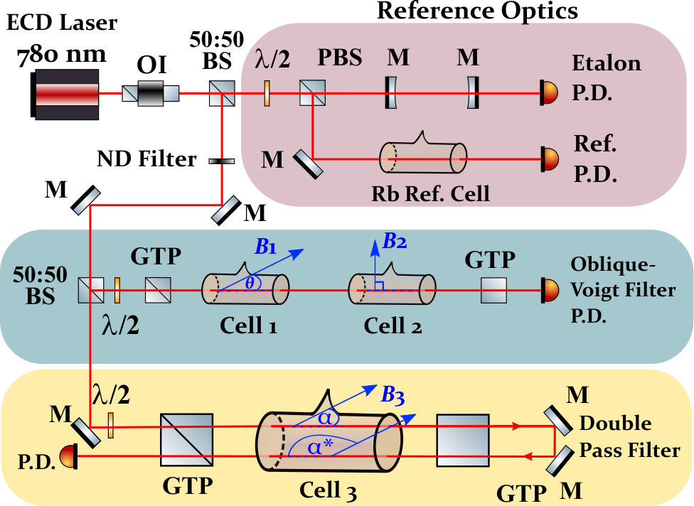 Figure 1
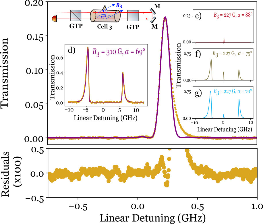 Figure 2
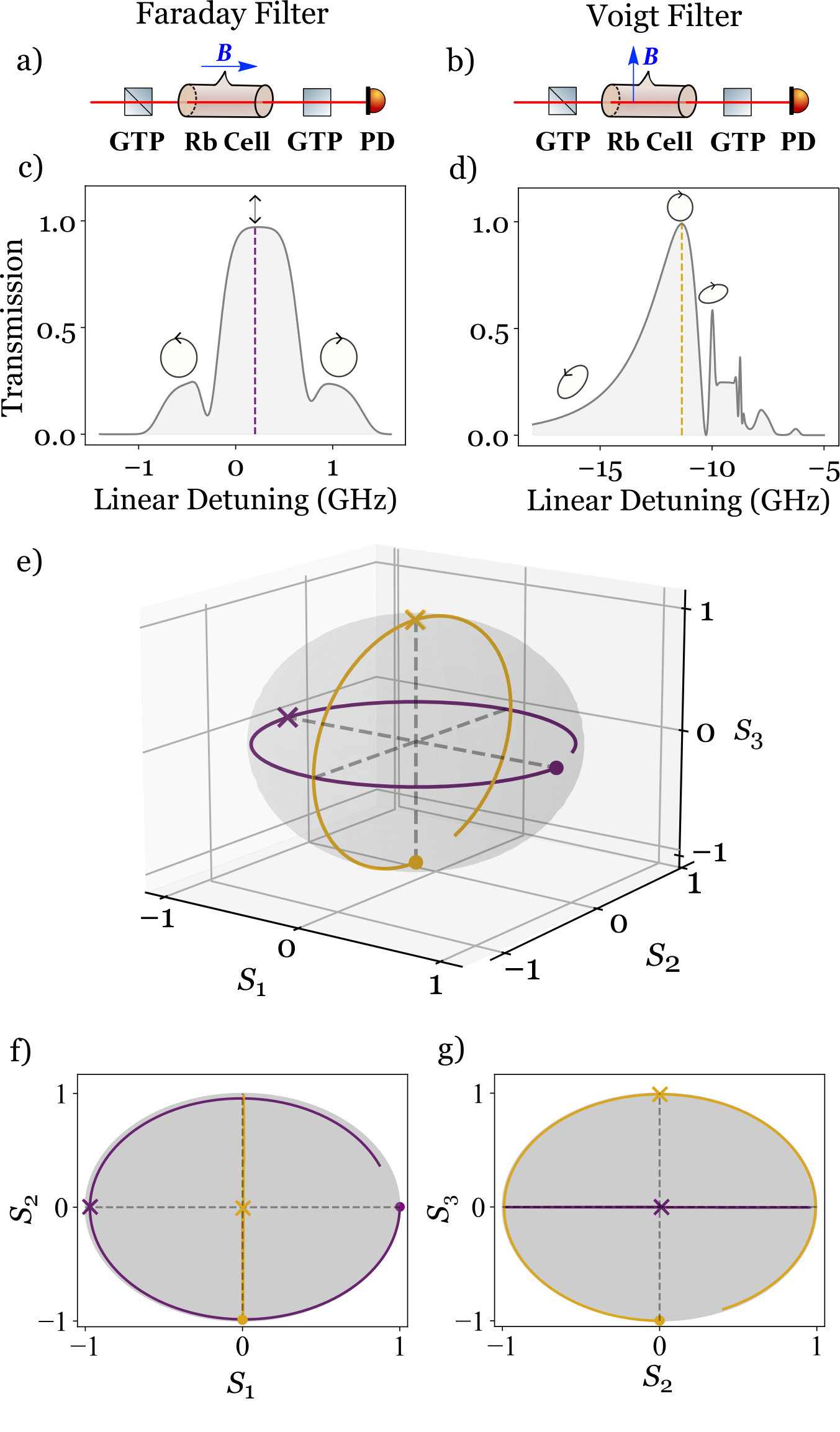 Figure 3
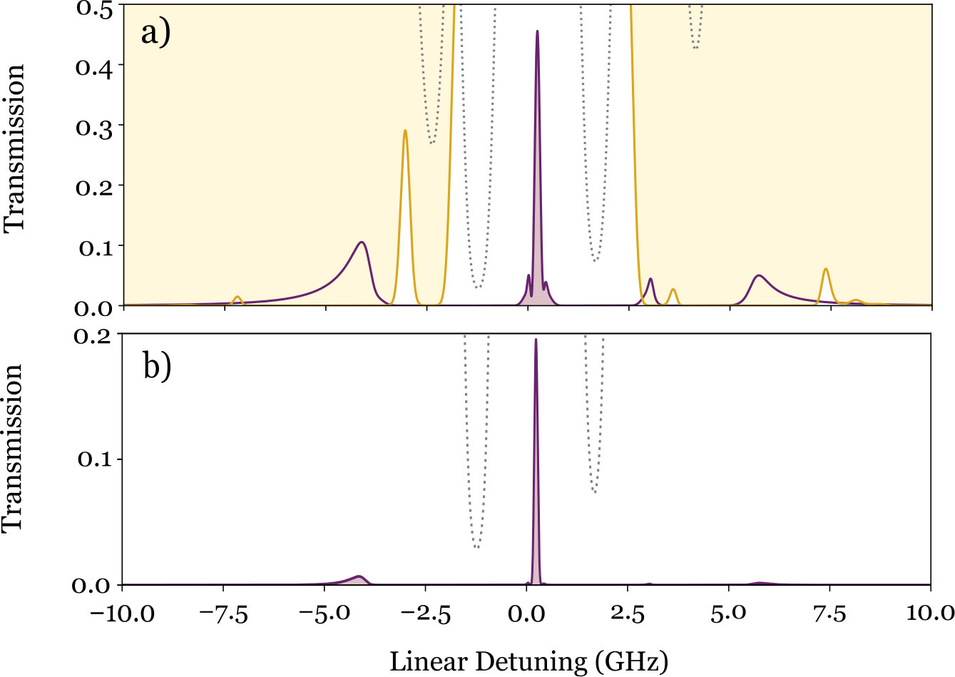 Figure 4
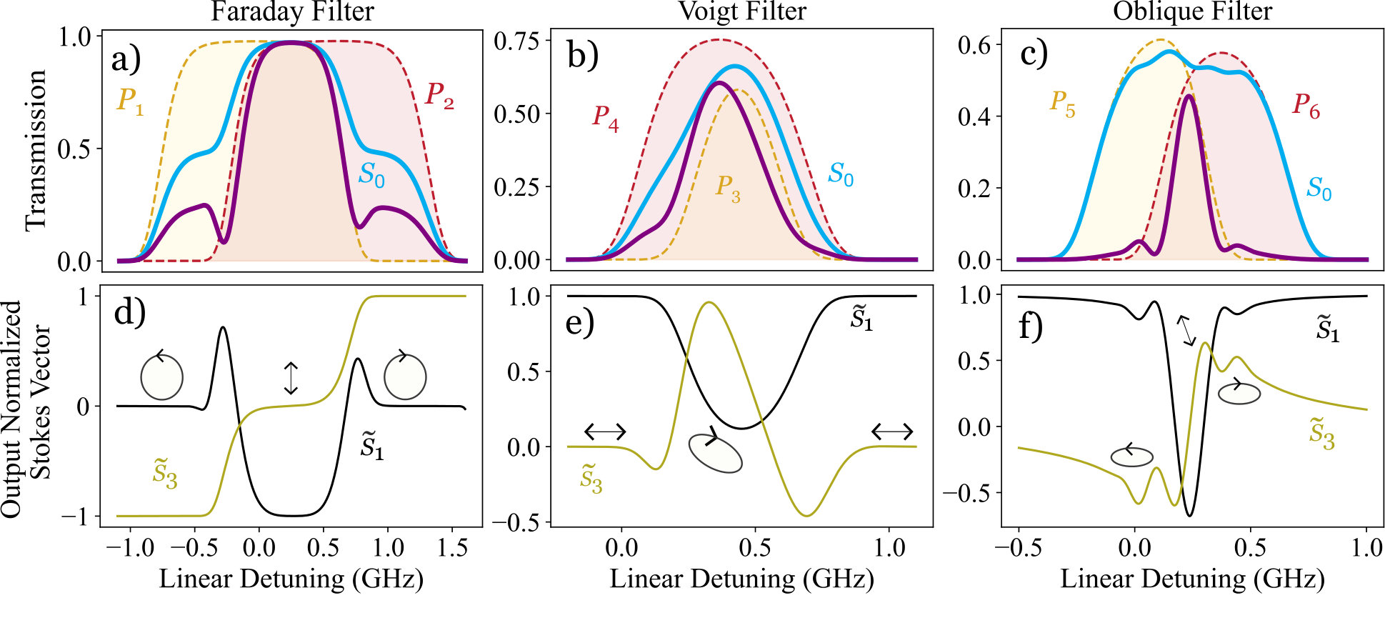 Figure 5
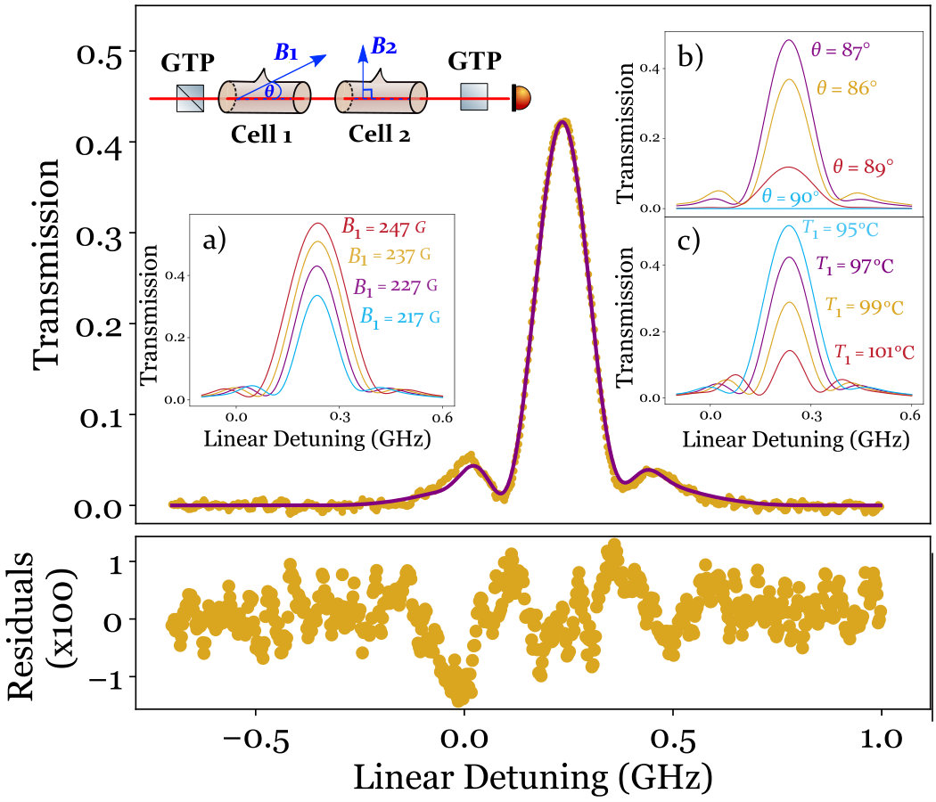 Figure 6
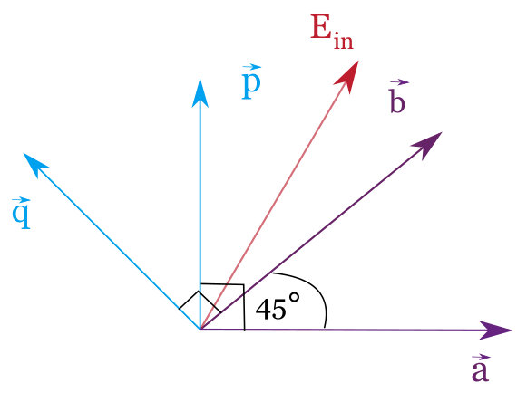 Figure 7
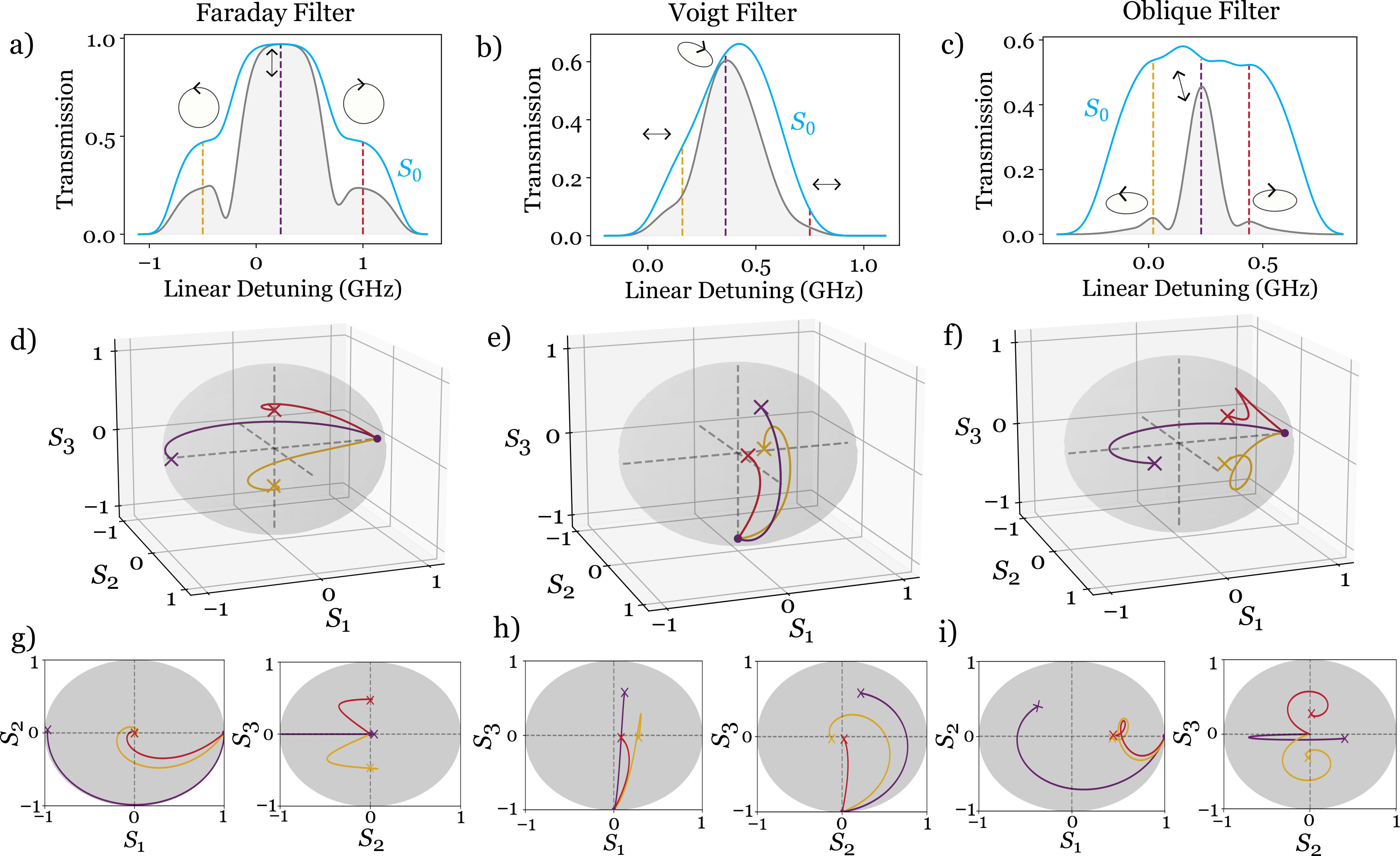 Figure 8
| Transmission Region | Invariant Pol. | Transitions Ind. |
|---|---|---|
| (Faraday) | L.H.C | |
| (Faraday) | R.H.C. | |
| (Voigt) | Lin. Hor. | |
| (Voigt) | Ver. Hor. | |
| (Oblique) | Freq. Dep. | |
| (Oblique) | Freq. Dep |
Peer Reviews
No public reviews on file for this paper yet. If you reviewed it on a platform where reviews are public (OpenReview, ICLR, NeurIPS, ICML), you can paste yours below so the community can read it here.
Videos
No videos yet. Explain this paper in a talk, walkthrough, or lecture? Add one.
Taxonomy
TopicsAdvanced Fiber Laser Technologies · Mechanical and Optical Resonators · Quantum Mechanics and Non-Hermitian Physics
Exploiting non-orthogonal eigenmodes in a non-Hermitian optical system to realize sub-100 MHz magneto-optical filters.
Fraser D. Logue
Department of Physics, Durham University, Durham, DH1 3LE, United Kingdom
Corresponding author: [email protected]
Jack D. Briscoe
Department of Physics, Durham University, Durham, DH1 3LE, United Kingdom
Danielle Pizzey
Department of Physics, Durham University, Durham, DH1 3LE, United Kingdom
Steven A. Wrathmall
Department of Physics, Durham University, Durham, DH1 3LE, United Kingdom
Ifan G. Hughes
Department of Physics, Durham University, Durham, DH1 3LE, United Kingdom
Abstract
Non-Hermitian physics is responsible for many of the counter-intuitive effects observed in optics research opening up new possibilities in sensing, polarization control and measurement. A hallmark of non-Hermitian matrices is the possibility of non-orthogonal eigenvectors resulting in coupling between modes. The advantages of propagation mode coupling have been little explored in magneto-optical filters and other devices based on birefringence. Magneto-optical filters select for ultra-narrow transmission regions by passing light through an atomic medium in the presence of a magnetic field. Passive filter designs have traditionally been limited by Doppler broadening of thermal vapors. Even for filter designs incorporating a pump laser, transmissions are typically less than 15% for sub-Doppler features. Here we exploit our understanding of non-Hermitian physics to induce non-orthogonal propagation modes in a vapor and realize better magneto-optical filters. We construct two new filter designs with ENBWs and maximum transmissions of 181 MHz, 42% and 140 MHz, 17% which are the highest figure of merit and first sub-100 MHz FWHM passive filters recorded respectively. This work opens up a range of new filter applications including metrological devices for use outside a lab setting and commends filtering as a new candidate for deeper exploration of non-Hermitian physics such as exceptional points of degeneracy.
††journal: optica
1 Introduction
Non-Hermitian physics [1, 2, 3, 4, 5, 6] is opening up new possibilities in photonics from the creation of omnipolarizers [7, 8, 9] to sensing applications [10, 11, 12] and tailoring laser output [13, 14, 15]. In general, non-Hermitian matrices do not guarantee orthogonal eigenvectors [16, 17, 18] and have real eigenvalues (PT-symmetric) [19, 20, 21], imaginary eigenvalues (anti-PT-symmetric) [22, 23, 24] or complex eigenvalues throughout [25, 26]. Ultra narrowband magneto-optical filters [27], which rely on complex refractive indices, are perfect candidates for non-Hermitian physics but have not yet been studied in this domain. Magneto-optical filters already see many applications in solar weather studies [28, 29, 30], laser frequency stabilization [31, 32, 33, 34, 35], LIDAR, [36, 37, 38], quantum hybrid systems [39], underwater optical communications [40] and ghost imaging [41]. Optimizing filters is a balance between maximizing transmission and minimizing bandwidth. For example, tens of MHz equivalent noise bandwidth at < transmission has been realized in active filters incorporating a pump beam [42, 43, 44]. On the other hand, several equivalent noise bandwidth has been realized at transmission in passive designs [45, 46]. A fundamental limit on linewidths has not yet been found and could have future implications for metrology [47, 48, 49].
Of equal importance is the platform, particularly when filters are designed for use outside a laboratory setting. Most magneto-optical filters rely on thermal vapor cells due to their compact and resilient setups [50]. Thermal vapor filters can be tuned by varying the magnetic field, temperature and input polarization [51, 52] and can switch between different D-line operation [53]. It has been shown that by cascading cells, line-center or wing features can be selected [54]. However the two setups require the rearrangement of optical elements and the interchange of kG permanent magnets with 100 G solenoids. Note that several metrological applications, such as those that use space, atmospheric or local environmental conditions to detect fluctuations, require apparatus that is robust to the elements [55, 56, 57]. Therefore there is interest in finding a reconfigurable setup that allows easy switching between wing and line-center operation.
The core principle of a magneto-optical filter is the magneto-optical rotation of light [58, 59, 60]. Faraday [61, 62, 63] and Voigt [64, 65, 66] filters, where the magnetic field is parallel or perpendicular to the -vector of the light, rely on circular or linear birefringence respectively. These are special cases where the eigenvectors are orthogonal even though the refractive indices are complex. By setting the magnetic field at an oblique angle to the -vector, the system becomes elliptically birefringent and dichroic [67, 68]. While oblique filters have been constructed [66, 69, 51, 70], a treatment on how elliptical birefringence can improve filter performance has not yet been presented. In fact, we show that this elliptical birefringence relies on the eigenmodes of the medium being non-orthogonal. This results in two improvements on the Faraday and Voigt cases: firstly, there is better rejection of light outside the birefringent region and secondly, the birefringent region is much narrower leading to narrower filter peaks and better figures of merit.
In this paper, we theoretically predict the benefits of oblique filters and experimentally realize two competitive filter designs. In Section 2, we show how oblique filters can reject light outside of the birefringent region at efficiency using Stokes parameters to characterise their performance. In Section 3, we demonstrate that this effect is explained by the oblique geometry having non-orthogonal eigenmodes and introduce the term invariant polarizations as the natural additional basis to explain oblique magneto-optical rotation. We calculate the birefringent region showing it to be narrower than the Faraday and Voigt cases. In Section 4, we realize two thermal vapor filters with lower equivalent noise bandwidth than previously published passive designs. Using naturally abundant Rb vapor, we experimentally realize the first Oblique-Voigt filter, a cascade of an oblique and a Voigt cell, and the first oblique double pass filter, a single oblique cell with light passed through twice. We find excellent agreement with data giving equivalent noise bandwidths and transmissions of 181 MHz, 42 % and 140 MHz, 17 % respectively. The first filter is the highest Figure of Merit (FOM) [52] passive filter to date. The second filter is the first sub-100 MHz FHWM passive design and is reconfigurable allowing the selection of line-center or wing features by solenoid current variation.
2 Elliptical Birefringence
The orientation of the magnetic field defines the relationship between input polarization and the induced () and () electric dipole allowed transitions [71, 69, 72]. In the Faraday geometry, a magnetic field is exerted parallel to the -vector of the input light which we take to be parallel with the -axis. This results in left/right handed circular light inducing transitions [73]. In the Voigt geometry, the magnetic field is perpendicular to the -vector and we have a choice of field lines running parallel to the - or -axis. Without loss of generality, in this paper, we always place magnets in the plane (i.e. on the surface of an optical bench). In this case, horizontally polarized light induces transitions and vertically polarized light induces a linear combination of and transitions [74].
Differences in the transition probabilities lead to polarization dependent absorption (dichroism) and continuous polarization state transformation (birefringence) as the light propagates through the vapor [75, 76]. The Faraday geometry exhibits a circular birefringence as differential refraction of circular handed light causes magneto-optical rotation of the plane of linear light. In contrast, the Voigt geometry exhibits linear birefringence where differential refraction of horizontally and vertically polarized light leads to the handedness cycling through right, linear and left hands. We can describe polarization evolution using Stokes parameters [77, 78] defined as,
[TABLE]
[TABLE]
represents the total transmission and is proportional to , the output intensity. , and together uniquely describe the polarization state. The arrow indices depict the polarization state of the output light ( denotes right/left hand circular light) and is a normalization factor. Throughout when we write , and , we are using input normalized stokes vectors . When we write tildes, , we are denoting output normalized stokes vectors .
Plotting Stokes parameters on a Poincaré sphere provides a useful way of visualizing polarization [52, 79, 80, 81]. In this paper, we explain filter performance by plotting the Stokes parameters as a function of the distance light has propagated through the vapor. A magneto-optical filter only outputs light that has rotated to be orthogonal to the input polarization. This is represented on the Poincaré sphere when curves travel to the antipode of the input (assuming no loss). Fig. 1 plots evolutions of maximum transmission frequencies for a Faraday and Voigt filter demonstrating circular birefringence, where the polarization evolves on the equator, and linear birefringence, where the polarization evolves along a meridian.
If a magnetic field is applied at an angle to the -vector, the projection operators for the three transitions are:
[TABLE]
The transition operator is always horizontally linear. If is an oblique angle, neither [math] or to the -vector, the transition operators are elliptical. Therefore, the oblique geometry exhibits elliptical birefringence where we have differential refraction between elliptical polarization states [67, 68]. A derivation of the projection operators can be found in Appendix A of the Supplementary Material.
In atom-light interactions, there is a birefringent region, where magneto-optical rotation occurs. In a Faraday/Voigt birefringent region, circular/linear birefringence results in linear/circular light as an output. Outside of the birefringent region, circular/linear dichroism of light outputs circular/linear light. Given that circular and linear light are not orthogonal polarization states, a filter cannot completely reject the output light outside the region but filters only . However, by choosing a suitable value of , it is possible to construct an oblique filter where light outside the birefringent region is suppressed beyond > 90%. Fig. 2 compares the filter transmissions of Faraday, Voigt and oblique filters with .
Note that the Faraday filter has characteristic pedestals either side of the central peak where circular light is rejected at 50%. In the Voigt filter, we also see 50% rejection for the selected negatively detuned frequency (gold). The positively detuned frequency (red) is rejected at > 50% but the S0 value is already less than 10%. However, the oblique filter demonstrates unparalled rejection of light outside the birefringent region significantly reducing the equivalent noise bandwidth, (ENBW),
[TABLE]
where is the transmission for a given frequency, , or the maximum transmission frequency, . In the literature, a Figure of Merit (FOM) [52],
[TABLE]
is often used to compare filter quality with a lower ENBW increasing FOM.
3 Birefringent Regions with Non-Orthogonal Eigenmodes
We can learn more about the magneto-optical rotation of a vapor by calculating the birefringent region explicitly. The birefringent region is the output where differential refraction occurs. Better filter peaks are formed within birefringent regions since they are highly selective resulting in narrower lineshapes and can rotate light with less loss. A filter may have additional transmission due to absorption both inside and outside of this region. Dichroic absorption alone evolves the polarization to one particular polarization state after which point moving through more vapor reduces the intensity of the light without altering the polarization state. This is a high loss process and as discussed in Section 2, light in this region is rejected by the filter at > 50%.
To compute the birefringent region we need to find a basis composed of polarizations which do not transform as they move through the vapor. We call these basis vectors invariant polarizations. In the Faraday and Voigt geometries, the invariant polarizations are the propagation eigenmodes derived from solving the wave equation [69]. We then calculate two regions, shown in red and yellow in Fig. 3, with the two eigenmodes as input polarizations. The overlap of the two regions is the birefringent region, shown in orange. In this detuning range, any input polarization with non-zero components of both eigenmodes undergoes continuous polarization state transformation.
However in the oblique geometry, the eigenmode solutions to the wave equation are non-orthogonal and frequency dependent. As such the eigenmodes are not invariant polarizations. Instead, we find the polarizations orthogonal to each eigenmode which do not undergo differential refraction. For more details, see Appendix B of the Supplementary Material. The full list of invariant polarizations is shown in Table 3. In particular, note that the oblique invariant polarizations generally induce all three transitions provided the three frequency dependent transition probabilities are non-zero.
In Fig. 3, we observe that the width of the birefringent region bounds the width of the filter peak. In the Faraday and oblique cases this is easier to see. In the Voigt case, one transmission region () lies entirely within the other (). The larger transmission of results in the center of the peak being displaced and some absorption outside the birefringent region contributing to the peak’s profile. The plotted oblique filter has the narrowest birefringent region resulting in the narrowest FWHM peak, two times and five times narrower than the Voigt and Faraday filters respectively.
Summarizing Sections 2 and 3, we can give a complete description of why the oblique filter can be tuned to give the best filter. Given that the invariant polarizations induce all three transitions, the regions and hence their overlap (the birefringent region) is narrower leading to narrower peaks. Outside of this region, dichroic absorption results in transformation to polarization states which can be filtered at > 90%. As such, the filter profile is improved as most light is transmitted within the birefringent region. The ENBW is also lower for this reason and additionally the FWHM of the peak is narrower. The detriment to maximum transmission does not outweigh the reduction in ENBW resulting in higher FOMs.
4 Experiment and Results
In order to test the advantages of the oblique geometry we realized two filter designs; the experimental setup is shown in Fig. 4. In the experimental arm, light on the Rb-D2 line with a beamwidth of passes through an ND filter to lower the power to 300 nW. We work in the weak probe regime [82, 83, 84] as it is readily available to model and higher intensity filters are outside the scope of this work.
The aim of the two filter designs is to output the desirable central filter features studied in previous sections while eliminating features away from center. Fig. 5 shows how the two designs eliminate unwanted features over a 20 GHz detuning range. The first experiment is a two cell cascade with the first cell in the oblique geometry and the second in the Voigt geometry. Both cells are between crossed Glan-Taylor polarizers. The two cells play different roles: Cell 1’s role is to create the narrow feature at center as studied in the previous sections while the role of Cell 2 is to absorb features away from the central region. A Voigt cell is particularly appropriate for this role since the magnetic field and temperature can be tuned to be highly absorptive away from center leaving a small transmission region at center for the narrow peak to be transmitted through. The theory behind the Voigt cell has been studied in [54]. This is the first Oblique-Voigt cascade recorded in the literature.
The second experiment is a double pass filter where light is passed through an oblique cell between polarizers and filtered before being reflected back into the cell and filtered again. The rays from the two passes follow a similar path and diverge by less than a 1 mm in the plane over the cell length. As the two beams are weak, neither beam pumps the atoms into higher states.
On the first pass, the light input is horizontally linear polarized and the magnetic field makes an angle to the propagation direction while on its second pass the light is filtered to be vertically linear polarized and the angle of the magnetic field is . The two passes individually give the same filter output. Left/right handed light propagating at an angle to the magnetic field is equivalent to right/left handed light propagating at an angle , however given we are inputting linear light the interchange of for results in no change. Additionally, horizontal and vertical input always gives the same filter output, provided the polarizers are rotated appropriately, regardless of the magnetic field angle (see Appendix C of the Supplementary Material). As such, filtering twice results in a squared intensity effect which suppresses the features away from center much more than the central features present after the first pass. Double pass filters have been realized before [85, 86, 87, 88] however never with an oblique cell.
Using an adapted version of the open-source software package ElecSus [89, 90], we found parameters for natural abundance Rb that would give a large FOM for the Oblique-Voigt filter and narrow FWHM for the double pass filter. We found that both of these objectives can be obtained using very similar parameters for Cell 1 and Cell 3. We chose 75mm cells for Cell 1 and Cell 3 and a 5mm cell for Cell 2. Choosing cells is an interplay between achieving a homogeneous magnetic field which is easiest in a small cell and avoiding collisional broadening effects which occur at higher temperatures. Hence if a large number density [91] is needed, longer cells may be better [92]. The combination of a solenoid and permanent magnets allows us to use a longer cell than in previous oblique investigations [70, 51] since the magnitude of the field is largely provided by the permanent magnets while its direction is determined by small adjustments in the solenoid current. This allows easier control of the field magnitude and direction with the permanent magnets set square with the cell resulting in less error in homogeneity.
The results and fit parameters are shown in Fig. 6. The data show excellent agreement with theory [93] apart from a shoulder on the double pass filter. The Oblique-Voigt filter has the highest FOM recorded to date of . The double pass has the highest FOM of a single cell passive filter recorded to date, , and has a sub-100 MHz fit FWHM of 93 MHz.
The insets on the left graph show the dependence of the Oblique-Voigt filter performance on , and . We note the high sensitivity to . If , there is no filter transmission since in the Voigt geometry linear horizontal light is not rotated. However as decreases, a filter profile quickly emerges showing the radical difference in the birefringence between the Voigt and oblique cases.
The insets on the right graph show how the double pass filter can be reconfigured to select for wing features over the line-center feature. This is achieved by raising the current which increases the axial field reducing the angle in the resultant field. We experimentally realize a wing filter using this procedure with the cuboidal magnets placed slightly closer to raise the magnitude of the magnetic field to . Such a feature would be very useful in a manufactured device where it may not be feasible to rearrange optical elements to achieve the same result.
5 Conclusion
In conclusion, we have presented the underlying non-Hermitian physics behind filters in the oblique geometry. We have shown that elliptical birefringence and non-orthogonal propagation eigenmodes can create narrower filters with greater rejection of light outside the birefringent region. We realized two new filter designs: an Oblique-Voigt cascade and an oblique double pass which showed excellent agreement with theory. These are the highest FOM and first sub-100 MHz FWHM passive design filters recorded respectively. These findings alongside the reconfigurability and compactness of the setup are promising for future applications in metrology outside a lab context [96, 97]. This is an initial work into non-Hermitian filter effects; our theory ElecSus predicts frequencies where the non-orthogonal eigenmodes almost completely coallesce suggesting the presence of exceptional points of degeneracy [98, 99, 100, 101]. In future work, we want to consider the additional sensing capabilities a device would have owing to exceptional points’ sensitivity for small parameter [11, 12].
\bmsectionFunding ESPRC Grant EP/R002061/1
\bmsection
Acknowledgments We would like to thank Thomas Robertson-Brown for their construction and characterization of the magnetic designs and Sharaa Alqarni for the use of their reference optics.
\bmsection
Disclosures The authors declare no conflicts of interest.
\bmsection
Data availability Data underlying the results presented in this paper are available in Ref. [102].
Appendix A: Deriving the Transition Projection Operators in the Oblique Geometry
We define as the propagation direction of the light and note that the light is polarized transversely in the plane. In the case where is the quantization axis, the angular part of the dipole matrix element is:
[TABLE]
where are the orbital, projection and total angular momentum quantum numbers and are spherical harmonic functions. However, since a plane wave is polarized transversely, we can omit operators. Therefore, in the Faraday geometry, where the -vector of the light is parallel with the magnetic field along , we have:
[TABLE]
Given that since , left/right handed circular light induces transitions in the Faraday geometry [73].
In the Voigt geometry, the -vector of the light is perpendicular to the magnetic field. Without loss of generality, we choose to rotate in the plane. As such, we substitute , in eq. 6. This gives the Voigt angular dipole matrix element:
[TABLE]
Therefore, horizontally polarized light induces transitions and vertically polarized light induces a linear combination of and transitions [74]. The reader can derive the expression if we instead rotate in the plane.
A general expression for all geometries is achieved by rotating the magnetic field by an angle . This gives the quantization axis transformations as:
[TABLE]
We then arrive at the general angular dipole matrix element by applying the transformations in Eq. 9 to Eq. 6:
[TABLE]
If the magnetic field is oblique to the -vector, the projection operators are elliptical for transitions and horizontally linear for transitions. However, the operators are non-orthogonal. Therefore, at least two transitions will be induced for any given input polarization (provided the probability of the transition in question is non-zero at the particular frequency).
Appendix B: Calculating Invariant Polarization States in the Oblique Geometry
Following the Jones Calculus method from [69], the propagation eigenmodes and form the conjugate transposed (†) rotation matrix,
[TABLE]
such that the input electric field is propagated to the output electric field as
[TABLE]
where is a diagonal matrix with first and second diagonal terms and , the function applied to the refractive indices and . These refractive indices are the eigenvalues associated with and respectively.
If an invariant polarization or is the input field to eq. 12, the output field will only depend on one of or . As such, no phase difference is induced and the polarization state does not evolve.
To calculate the invariant polarizations, we can choose a state orthogonal to an eigenmode. Formally, we say that the invariant polarizations and eigenmodes together form a biorthogonal system [16].
The need for a biorthogonal system is a direct result of a non-Hermitian system Hamiltonian [2, 3, 4, 5, 6]. The eigenvalues (refractive indices) and are in general complex.
In the Faraday and Voigt cases, the eigenmodes are orthogonal. Therefore, the invariant polarizations are the eigenmodes and we say the system is orthonormal provided the eigenmodes are normalized.
We prove this in the Faraday case where the eigenmodes are left hand and right hand circular light. We input an eigenmode, left hand circular light,
[TABLE]
The final output field is the same as the input field multiplied by a factor so the eigenmode is also an invariant. Similarly, we prove this in the Voigt case where the eigenmodes are horizontally and vertically linear light. We input horizontally linear light,
[TABLE]
Like the Faraday case, the output field is the input field multiplied by a factor and so the eigenmode is also an invariant polarization.
In the oblique case, the eigenmodes and the invariant polarizations are not one and the same since the oblique eigenmodes are in general non-orthogonal. Without loss of generality, we choose the left hand orthogonal vectors to the eigenmodes as our oblique invariant polarizations,
[TABLE]
with ∗ indicating the complex conjugate.
We illustrate this situation using a toy expression. Fig. 7 is a diagram of the relevant eigenmodes and invariant polarizations. Our eigenmodes will be two non-orthogonal polarizations: horizontally polarized light and linear light at 45∘. We input linear horizontally polarized light. Eq. 12 then gives,
[TABLE]
While we have input an eigenmode, since the eigenmodes are not orthogonal, the polarization is not invariant. We can decompose the result into two invariant polarizations, linear diagonal light at and vertically polarized light. Note the relationship between the eigenmodes and the invariant polarizations is as described in eq. 15.
Into the same system, we input an invariant polarization, vertically linear light, and prove its invariance,
[TABLE]
Of importance to emphasize is this is a toy example. Horizontally linear light and linear light at could never jointly form the eigenmodes of a system. This is because is a rotation matrix for some angle and multiplicative factor implying a constraint,
[TABLE]
The eigenmodes of the Faraday and Voigt geometry respectively adhere to this constraint. The constraint implies elliptical eigenmodes in the oblique geometry.
Appendix C: Equivalent Propagation of both passes in the Double Pass Filter
We consider first the different angles between magnetic field and propagation direction of both passes, and . Equivalently, we can say in the second pass the magnetic field makes an angle with a vector pointing in the opposite direction to .
In this picture, the relevant axis for identifying polarizations has flipped. Instead of looking at the electric field towards the source, we should view it looking from the source. Therefore, left/right handed polarizations now appear to be right/left handed.
Given that everything else remains identical, we can say that the evolution of a left/right handed wave with magnetic field at angle to the -vector is the same as the evolution of a right/left handed wave with magnetic field at angle to the -vector. If linearly polarized light is input, the filter transmission will not differ in the two cases.
The filter output from a horizontally () or vertically () polarized input with crossed polarizers is always the same regardless of geometry,
[TABLE]
where and are vertically and horizontally linear polarizers respectively. This follows directly from eq. 18. The two facts stated above explain why both passes of the double pass filter have the same filter transmission.
The reference list from the paper itself. Each links out to its DOI / PubMed record.
- 1[1] A. Siegman, “Excess spontaneous emission in non-Hermitian optical systems. I. Laser amplifiers,” \Journal Title Physical Review A 39 , 1253 (1989).
- 2[2] M. V. Berry, “Physics of nonhermitian degeneracies,” \Journal Title Czechoslovak Journal of Physics 54 , 1039–1047 (2004).
- 3[3] C. M. Bender, “Making sense of non-Hermitian hamiltonians,” \Journal Title Reports on Progress in Physics 70 , 947 (2007).
- 4[4] M. Berry, “Optical polarization evolution near a non-Hermitian degeneracy,” \Journal Title Journal of Optics 13 , 115701 (2011).
- 5[5] R. El-Ganainy, M. Khajavikhan, D. N. Christodoulides, and Ş. K. Özdemir, “The dawn of non-Hermitian optics,” \Journal Title Communications Physics 2 , 1–5 (2019).
- 6[6] R. El-Ganainy, K. G. Makris, M. Khajavikhan, Z. H. Musslimani, S. Rotter, and D. N. Christodoulides, “Non-Hermitian physics and PT symmetry,” \Journal Title Nature Physics 14 , 11–19 (2018).
- 7[7] A. U. Hassan, G. L. Galmiche, G. Harari, P. Li Kam Wa, M. Khajavikhan, M. Segev, and D. N. Christodoulides, “Chiral state conversion without encircling an exceptional point,” \Journal Title Physical Review A 96 , 052129 (2017).
- 8[8] A. U. Hassan, B. Zhen, M. Soljačić, M. Khajavikhan, and D. N. Christodoulides, “Dynamically Encircling Exceptional Points: Exact Evolution and Polarization State Conversion,” \Journal Title Physics Review Letters 118 , 093002 (2017).