Q-Map: Quantum Circuit Implementation of Boolean Functions
Hassan Hajjdiab, Ashraf Khalil, Hichem Eleuch
TL;DR
This paper introduces Q-Map, a visual technique for implementing classical Boolean functions on quantum computers, aiming to optimize quantum gate usage and facilitate quantum algorithm development.
Contribution
The paper presents a novel visual method, Q-Map, for efficiently translating Boolean functions into quantum circuits with minimal gates.
Findings
Q-Map effectively reduces quantum gate count.
The method simplifies quantum circuit design for Boolean functions.
Q-Map enhances the practicality of quantum logic implementation.
Abstract
Quantum computing has gained attention in recent years due to the significant progress in quantum computing technology. Today many companies like IBM, Google and Microsoft have developed quantum computers and simulators for research and commercial use. The development of quantum techniques and algorithms is essential to exploit the full power of quantum computers. In this paper we propose a simple visual technique (we call Q-Map) for quantum realisation of classical Boolean logic circuits. The proposed method utilises concepts from Boolean algebra to produce a quantum circuit with minimal number of quantum gates.
Click any figure to enlarge with its caption.
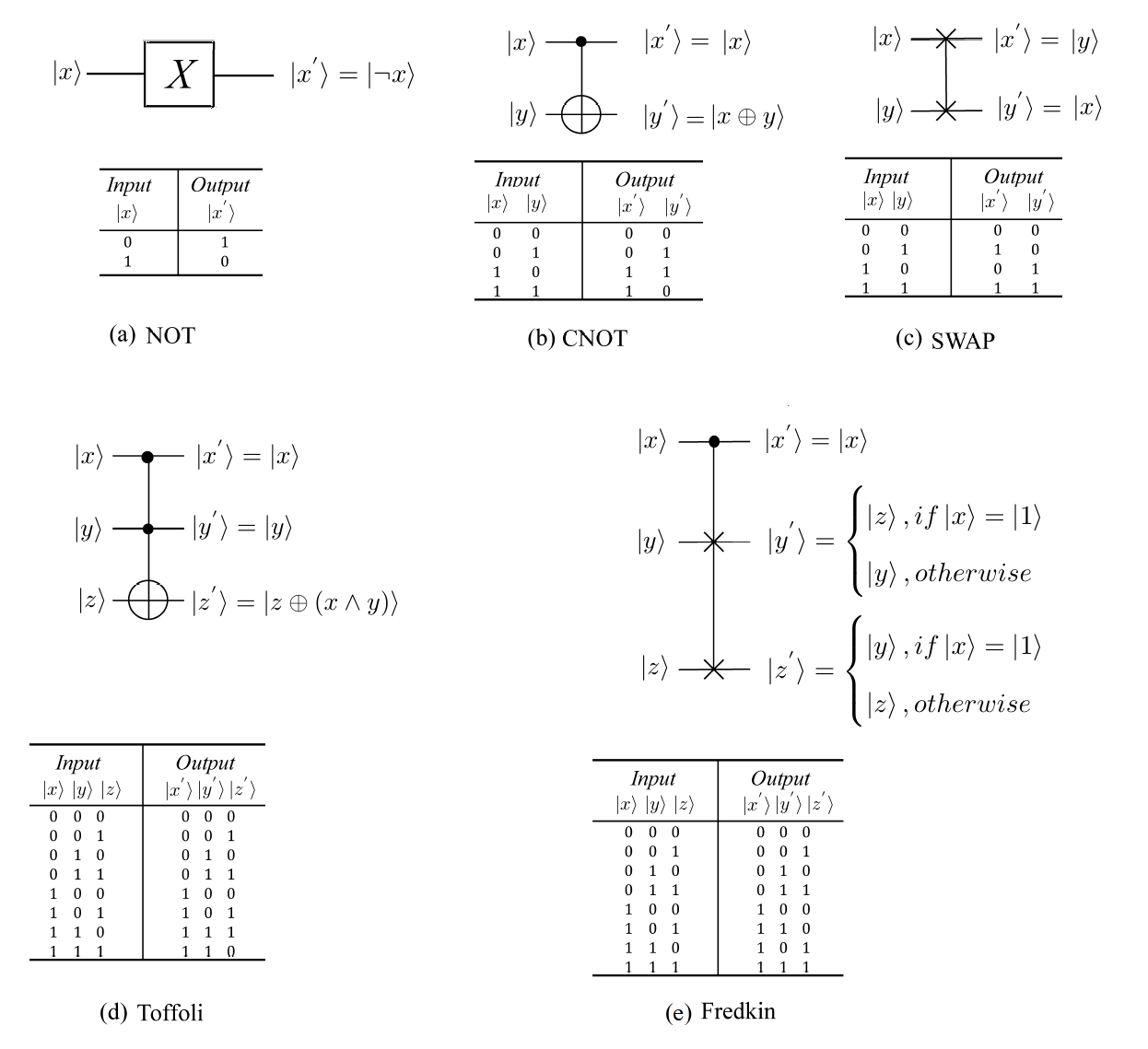 Figure 1
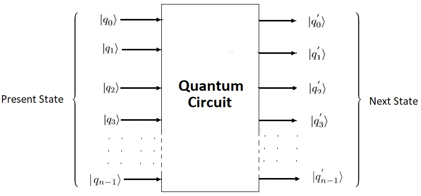 Figure 2
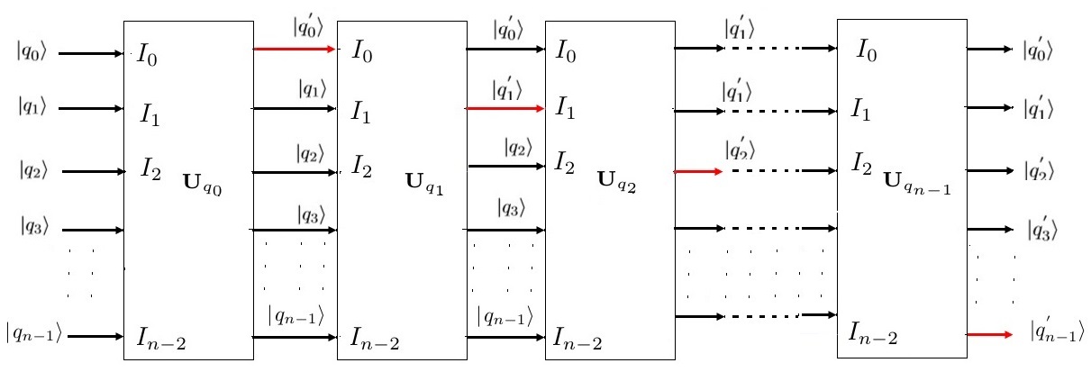 Figure 3
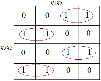 Figure 4
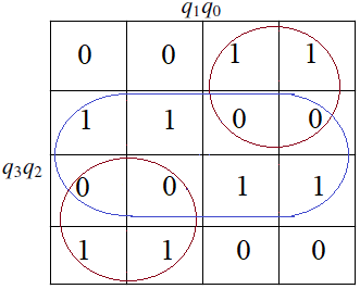 Figure 5
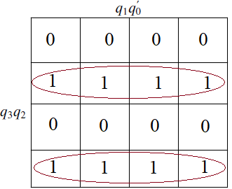 Figure 6
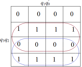 Figure 7
 Figure 8
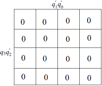 Figure 9
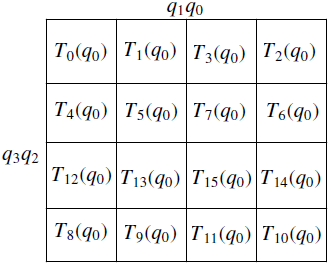 Figure 10
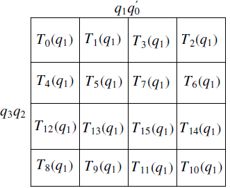 Figure 11
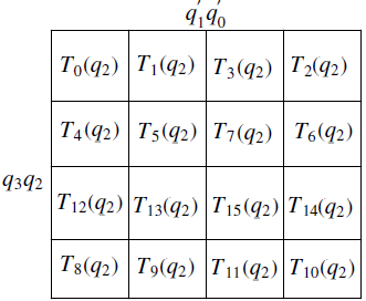 Figure 12
 Figure 13
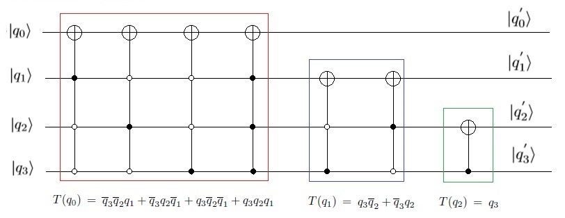 Figure 14
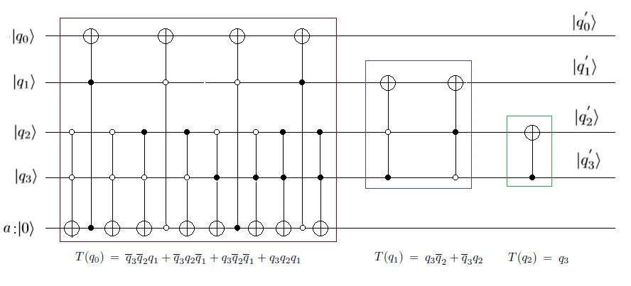 Figure 15
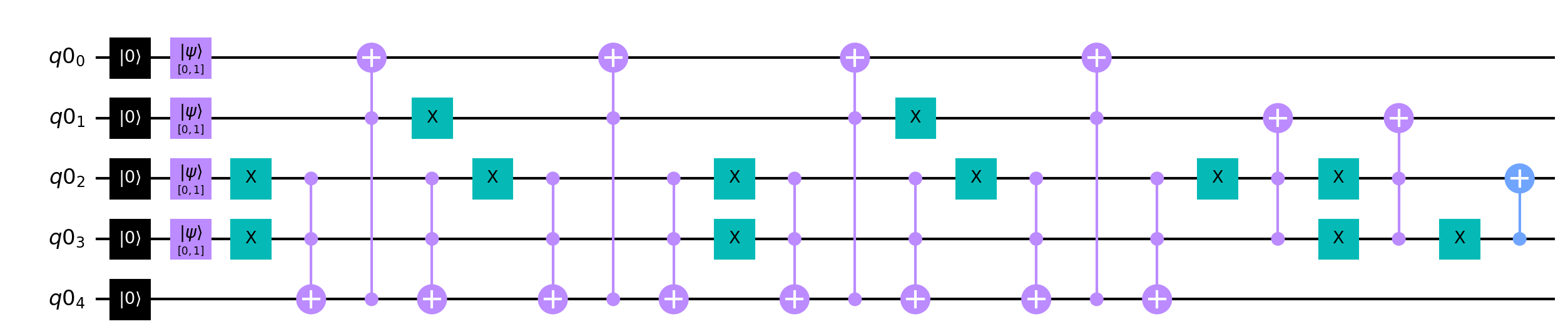 Figure 16
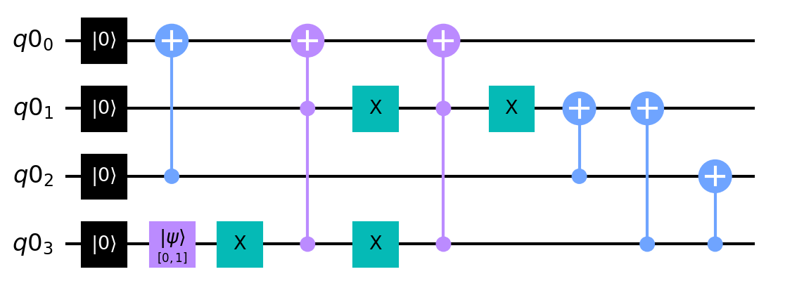 Figure 17
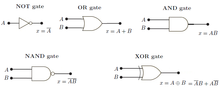 Figure 18
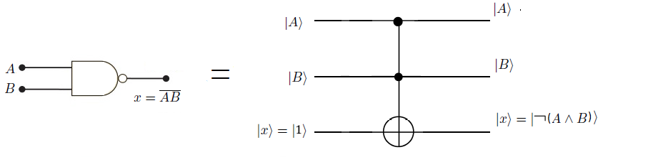 Figure 19
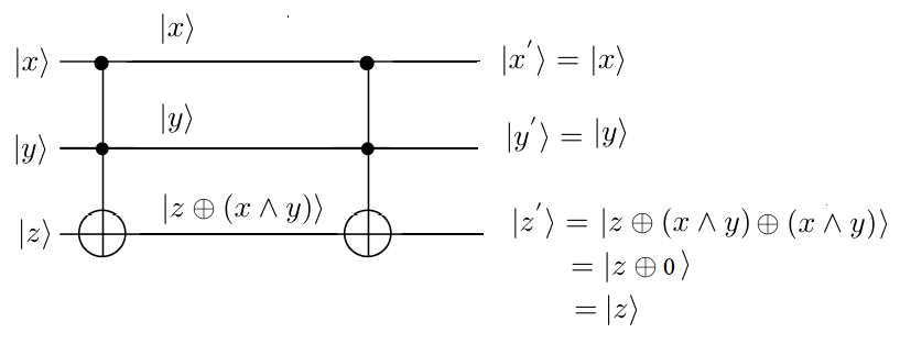 Figure 20
| Present Sate | Next State | Toggle function |
| Present State | Next State |
| Present State | Next State | Toggle Functions | |||
|---|---|---|---|---|---|
Peer Reviews
No public reviews on file for this paper yet. If you reviewed it on a platform where reviews are public (OpenReview, ICLR, NeurIPS, ICML), you can paste yours below so the community can read it here.
Videos
No videos yet. Explain this paper in a talk, walkthrough, or lecture? Add one.
Taxonomy
TopicsQuantum Computing Algorithms and Architecture
Q-Map: Quantum Circuit Implementation of Boolean Functions
Hassan Hajjdiab1,*, Ashraf Khalil2, Hichem Eleuch3,4,5,
1 Computer Science and Software Engineering Department, Concordia University, Montreal, Quebec, Canada; Email: [email protected]
2 College of Technological Innovation, Zayed University, Abu Dhabi, UAE; Email: [email protected]
3 Department of applied physics and astronomy, University of Sharjah, Sharjah, UAE; Email: [email protected]
4 College of Arts and Sciences, Abu Dhabi University, Abu Dhabi 59911, UAE
5 Institute for Quantum Science and Engineering, Texas A&M University, College Station, TX 77843, USA
*Author to whom correspondence should be addressed
Abstract
Quantum computing has gained attention in recent years due to the significant progress in quantum computing technology. Today many companies like IBM, Google and Microsoft have developed quantum computers and simulators for research and commercial use. The development of quantum techniques and algorithms is essential to exploit the full power of quantum computers. In this paper we propose a simple visual technique (we call Q-Map) for quantum realisation of classical Boolean logic circuits. The proposed method utilises concepts from Boolean algebra to produce a quantum circuit with minimal number of quantum gates.
Introduction
The advancement of quantum computing hardware and software intrigues researchers to develop quantum algorithms in areas such as cryptography, image processing, algorithms, finance [10, 15, 13, 6] and many other areas. One main advantage of quantum computers compared to classical computers is the processing power. The quantum computer can process computationally expensive tasks exponentially faster than the classical computer. While classical algorithms are limited in complexity to , a quantum search algorithm proposed by Grover [8] uses for unsorted list of items. Shor [23] proposed a quantum algorithm to factor an integer in polynomial of log time complexity. At this point, there is no classical algorithm that can solve number factorisation in polynomial time.The RSA cryptographic system [20] is based on prime number factorisation, and thus with quantum computers an RSA encrypted message can be decrypted in polynomial time complexity. Hallgen [9] presented a polynomial-time quantum algorithm to solve the Pell-Fermat equation [3] ( also known as the Pells equation 111Pell-Fermat equation is: and the goal is to find pairs of integers to satisfy the equation). In classical algorithm there is no know polynomial time solution and the problem is know to be NP complete [4]. Recently, a group of scientists at Google AI Quantum [2] used qubit quantum computer to sample the output of a pseudo-random quantum circuit [18]. The results were compared with the sate-of-the art super computer that needs 10,000 years while the 53 qubit quantum computer needs seconds.
Another advantage of quantum computers is low energy consumption. In computation, energy consumption is correlated with reversibility of the computation. Irreversibly is equivalent to information erasure. For the case of an AND gate of output 0, we may say that we cannot uniquely identify the input, the AND operation resulted in erasure of information and thus consumed energy [14]. As demonstrated by Landauer [14], classical binary computers mainly dissipate energy during information erasure at the rate of per bit erased, where is the Boltzmann constant and is the temperature in Kelvins. At room temperature (300 Kelvin), each bit erasure will cost around . This number appears to be too small, however the digital binary computer is composed of huge number of Boolean logic gate operations at the hardware level which results in significant consumption of energy. On the other hand, quantum computers utilise quantum gates which are all reversible gates and thus quantum computation do not result in energy consumption.
In this paper we propose a simple visual technique (we call Q-Map) for quantum realisation of classical Boolean logic circuits. Classical boolean computation can be described in terms of classical boolean functions. To perform classical computations using a quantum computer, the classical boolean function need to be synthesised using reversible functions.
Overview of classical and Quantum gates
A Boolean function with inputs and outputs is defined as:
, where the Boolean values are denoted by .
A function is reversible if it is bijective [21], each input map exactly to one output and the number of inputs is equal to the number of outputs.
Classical Binary computers are, in essence, composed of irreversible logic gates. Other than the NOT gate, the binary logic gates are irreversible gates ( see Figure 1 ). For example the classic AND gate is irreversible, for an output of 0 the input could be 00, 01 or 10 and cannot be uniquely identified.
On the other hand, a quantum bit (or qubit) x represents a unit of information and can be described in a two dimensional quantum system as follows:
\ket{x}=\left[\begin{array}[]{c}c_{0}\\ c_{1}\end{array}\right] where
The quantum states of and are represented by the vectors \ket{0}=\left[\begin{array}[]{c}1\\ 0\end{array}\right] and \ket{1}=\left[\begin{array}[]{c}0\\ 1\end{array}\right]
The qubit can be in an ”on” or ”off” states as in the classical Boolean computers or in any combination of the ”on-off” states : , where . To represent a classical digital system the qubit and are sufficient. Figure 2 shows the commonly used quantum gates, all quantum gates are reversible and the input can be reconstructed from the output by applying the gate twice. Figure 3 shows an example using the Toffoli gate, the input can be reconstructed by applying the Toffolli gate twice.
In this paper we propose a technique to implement a binary logic circuit using a quantum gates, and thus only the and states of the qubit are utilised. In classical Boolean circuits, the NAND gate is a universal gate and all other Boolean gates could be constructed using one or more NAND gates[27]. Any Boolean logic circuit can be designed using reversible quantum gates, the logic gates presented in Figure 1 can be constructed using a combination of the NOT, CNOT and Toffoli gates, thus the NOT-CNOT-Tofolli gates form a universal basis for quantum circuit implementation [19, 31, 5]. Figure 4 shows quantum reconstruction of the NAND gate using a Toffoli gate, the quantum equivalent requires an extra bit ( i.e ancillary bit ).The rest of the boolean gates can be synthesised using the NOT-CNOT-Tofolli bases.
Thus any Boolean function can be synthesised by simply replacing each Boolean gate by its quantum counterpart. However this approach is hardly efficient and leads to a significant number of ancillary bits [17, 30]. In literature several approaches have been proposed [12, 7, 25, 24, 29, 28] to synthesise a given Boolean function with minimal number of ancillary bits. Most of the approaches rely on heuristic methods to minimise the costs of the resulting circuits using complex function manipulation [11]. In this paper we present an exact method to realise the quantum implementation of any classical binary system. The technique (we call Q-Map) is analogous to the Karnaugh Map [27] for classical logic gate minimisation technique. The main contribution of this paper is as follows:
- •
We propose a visual method to synthesise any Boolean functions without having to resort to complex function decomposition and manipulation.
- •
We demonstrate the algorithm by implementing the 4-bit Gray Code Encoder using QISKIT.
Quantum-Map technique
In our proposed approach, the problem is modelled as a quantum circuit with input quantum bits () that represents the initial state of every qubit and output quantum bits () that represent the final state of each bit (see Fig. 5 (a)). The quantum circuit is further decomposed into a series of cascaded stages . Each stage is a quantum circuit with input qubits represented by the vector and output qubits represented by the vector where qubit is altered and the rest of the qubits are unaltered, the stages are presented in Fig. 5 (b).
The relationship between the input vector and the output qubit at stage is defined by a control function as follows:
[TABLE]
Where is a control function that computes a new value at the target output and leaves all other variables unaltered. Equation 1 can be expanded as:
[TABLE]
As presented in Equation 2, the input vector includes all qubits, thus the quantum circuit will calculate (i.e the next state of ) as a function of qubits. The output vector is an qubit vector where only qubit is changed to based on value of the control function and the rest of the qubits are unchanged. To calculate , the output qubit from the previous stage will be used. In general, the input vector for any stage is the vector and the output is the vector .
To calculate for each stage, we follow a function minimisation approach inspired by the Karnaugh Map technique [27] for Boolean function minimisation. Our proposed approach starts by building a logic map for the function to be minimised we call it the Quantum Map (Q-Map). The Q-Map is a two-dimensional array of cells used to represent a switching function. The switching function , presented in Table 1, represents the toggle state of a qubit from the present state to the next state (i.e toggle from to or from to ). The function can be represented as the logical XOR of the current state with the next state as presented in Table 1.
is a function of qubits denoted by , the Q-Map of the stage is composed of two vectors and with a row for each assignment of for a total of and with a column for each assignment of for a total of columns. Similar to the Karnaugh Map, the adjacency condition is established by labelling the rows and the columns such that for any adjacent rows ( or columns) differ only in variables. Fig. 6 shows the Q-Map to find the quantum circuit with four variables. In each cell the corresponding value of the switching function is inscribed. Using the Q-Map, a minimal expression is calculated for each qubit. And finally the quantum circuit is implemented using the quantum gate basis.
To demonstrate our proposed approach, we present a quantum circuit implementation of the Gray Code to Binary converter. The details of proposed algorithm with the reversible circuit implementation are presented in the next section.
Implementation of the Gray Code Encoder
In this section we demonstrate the technique by implementing the Gray Code to Binary converter. The Gray Code is used in many applications such as position control systems, communications and many other areas [16]. The Gray code provides a binary code that changes by one bit only when it changes from one state to the next. The Gray code and the corresponding decimal unsigned binary equivalent is shown in Table 2.
The first step starts by building the switching function for each quantum bit as described in Table 1. The function for each qubit is calculated as:
[TABLE]
The result is presented in Table 3
The second step is to establish the Q-Map for each qubit. Figure 7 (a) shows the Q-Map to evaluate given the values of the input , and . A value of in the Q-Map represents the state of , and when toggles its state. Thus will toggle its state when the following expression is true:
[TABLE]
Figure 7 (b) shows the Q-Map to find . The expression is calculated based on inputs , and as follows:
[TABLE]
Figure 7 (c) shows the Q-Map to find . The expression is calculated based on inputs , and as follows:
[TABLE]
Finally, figure 7 (d) shows the Q-Map to find . The expression is calculated based on the inputs , and as follows:
Notice here we use the XOR () operation and the function is represented in Exclusive-OR Sum-of-Product form (ESOP) form since the qubit will toggle only if we have an odd number of true terms. For even number of true terms the qubit will retain its initial state. In classical Boolean function minimisation using Karnaugh Map the logic OR () operation is used and the function is expressed in Sum of Product (SOP) form since the Boolean function will be true if any of the terms is true and so group overlap is allowed.
In our proposed Q-Map approach group overlap is not allowed, this makes all terms in every function mutually exclusive and only one term can be true at one instant of time. Thus the XOR () operation can be replaced by the OR () operation and the function can be represented in the Sum of Product (SOP) form. Since each Q-Map in Figure 7 contains no overlapping groups, the functions can be represented in Sum of Product (SOP) form as follows:
[TABLE]
The functions presented in Equation 10 can be realised by a reversible circuit with only four lines (i.e. lines) using the NOT-CNOT-Toffoli bases with Multi-Control Toffolli gates [22]. This means that the implementation is efficient and no temporary lines (also referred as ancilla) are needed. The quantum circuit can be implemented using CNOT and two and three input Toffoli gates as shown in Figure 8.
The quantum circuit is also simulated using QISKIT open-source framework simulator for quantum circuit [1, 26]. In QISKIT, the Toffoli gate is composed of two control inputs and one output. To implement the circuit in Figure 8, we redesigned the quantum circuit to include 2-input Toffoli gates; however an additional ancillary qubit is needed to store the intermediate values. The design with 2-input Toffoli gates is presented in Figure 9. The code to simulate the qunatum gray to binary converter is presented in Figure 11.
The Q-Map algorithm can be summarised as follows:
- Step 1: For each qubit build the toggle function as the logical Exclusive-OR of the present state and the final state .
- **Step **2 :Establish the Q-Map of the switching function as a function of the qubits .
- Step 3: In each cell inscribe the value of in the Q-Map.
- Step 4: Find the expression of in Sum-Of-Product form using the Q-Map such that:
-
Groups should be as large as possible
-
Group Overlapping is not allowed
- Step 5: For each expression use the CNOT-NOT-Toffoli bases to implement the corresponding quantum circuit.
Q-Map optimisation
In classical boolean function minimsation using the Karnaugh map, the entry inscribed in every cell indicates the value of the boolean function at the corresponding state. However in our proposed approach, the entry inscribed in each cell in the Q-map indicates change of state of the function. An entry of in th Q-map indicates that the function must change state (i.e toggle) and a value of [math] indicates the function must remain in the same state. Thus including the in the Q-map in an odd number of groups will result in one change of state and including the in even number of groups will result in no change of state. This property of the Q-map could be used in our advantage to maximise the number of Q-map cells in each group and produce a more simplified expression that minimises the quantum cost of the design.
The optimised Q-Map algorithm can be summarised as follows:
- Step 1: For each qubit build the toggle function as the logical Exclusive-OR of the present state and the final state .
- **Step **2 :Establish the Q-Map of the switching function as a function of the qubits .
- Step 3: In each cell inscribe the value of in the Q-Map.
- Step 4: Find the expression of in Sum-Of-Product form using the Q-Map such that:
Groups should be as large as possible and may include and . 2. 2.
Every must be included in an odd number of groups 3. 3.
If a [math] is included, it must be included in an even number of groups
- Step 5: For each expression use the CNOT-NOT-Toffoli bases to implement the corresponding quantum circuit.
To demonstrate the idea, we re-evaluate the functions produces in the Q-map of Figure 7 as shown in Figure 12 and the functions presented in Eq. 10 can be replaced by :
[TABLE]
Other alternative designs are possible, for example, can be also written as .
Based on the functions in Eq.11, the quantum circuit can be designed as presented in Figure 13 and the corresponding QISKIT code is shown in Figure 14. The optimised approach re-designed the quantum circuit with no ancillary bits and significantly reduced the number of quantum gates.
Conclusion
In this paper we propose a visual method for quantum realisation of classical Boolean logic functions. The proposed method utilise concepts from Boolean algebra to produce a quantum circuit with minimal number of quantum gates. The proposed technique is composed of three steps: (1) for each quantum bit build a switching function , (2) establish the Q-Map for and (3) using the Q-Map find the quantum expression to implement the switching function using the NOT-CNOT-Toffoli quantum gate basis.The proposed method is demonstrated by implementing the Gray-Code Encoder.
The reference list from the paper itself. Each links out to its DOI / PubMed record.
- 11. Learn quantum computation using qiskit, May 2023.
- 22. F. Arute et al. Quantum supremacy using a programmable superconducting processor. Nature , 574:505–510, 2019.
- 33. E. Barbeau. Pell’s Equation . Problem Books in Mathematics. Springer, 2003.
- 44. J. Buchmann and H. C. Williams. On the existence of a short proof for the value of the class number and regulator of a real quadratic field. in: Richard A. Mollin (ed.), Number Theory and Applications, (NATO — Advanced Study Institute, Banff, 1988 ) Dordrecht: Kluwer , pages 327–345, 1989.
- 55. T. T. E. Fredkin. Conservative logic. International Journal of Theoretical Physics , 21:219–253, 1982.
- 66. D. J. Egger, C. Gambella, J. Marecek, S. Mc Faddin, M. Mevissen, R. Raymond, A. Simonetto, S. Woerner, and E. Yndurain. Quantum computing for finance: State-of-the-art and future prospects. IEEE Transactions on Quantum Engineering , 1:1–24, 2020.
- 77. K. Fazel, M. A. Thornton, and J. E. Rice. Esop-based toffoli gate cascade generation. 2007 IEEE Pacific Rim Conference on Communications, Computers and Signal Processing , pages 206–209, 2007.
- 88. L. K. Grover. Quantum mechanics helps in searching for a needle in a haystack. Phys. Rev. Lett. , 79:325–328, Jul 1997.