Performance tests of boron-coated straw detectors with thermal and cold neutron beams
Georg Ehlers, Athanasios Athanasiades, Liang Sun, Christopher S., Martin, Murari Regmi, Jeffrey L. Lacy

TL;DR
This paper evaluates boron-coated straw detectors for thermal and cold neutron detection, demonstrating they match or surpass traditional 3He detectors in efficiency, resolution, and noise performance, suitable for scientific applications.
Contribution
It introduces and benchmarks a new boron-coated straw detector technology against industry-standard 3He detectors in neutron detection performance.
Findings
BCS detectors achieve near theoretical detection efficiency.
BCS perform comparably to 3He tubes in signal-to-noise ratio and timing.
BCS have superior longitudinal spatial resolution.
Abstract
Prototypes of newly developed boron-coated straw (BCS) detectors have been tested in the thermal and cold neutron energy ranges. Their neutron detection performance has been benchmarked against the industry standard (detector tubes filled with 3He gas). The tests show that the BCS straws perform near their theoretical limit regarding the detection efficiency, which is adequate for scientific instruments in the cold neutron energy range. The BCS detectors perform on par with 3He tubes in terms of signal to noise and timing resolution, and superior regarding longitudinal spatial resolution.
Click any figure to enlarge with its caption.
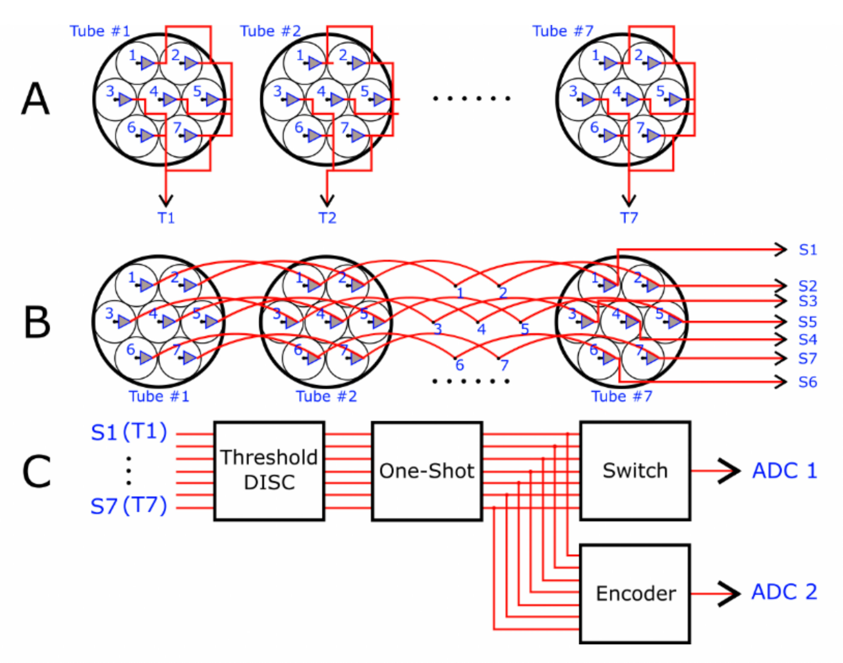 Figure 1
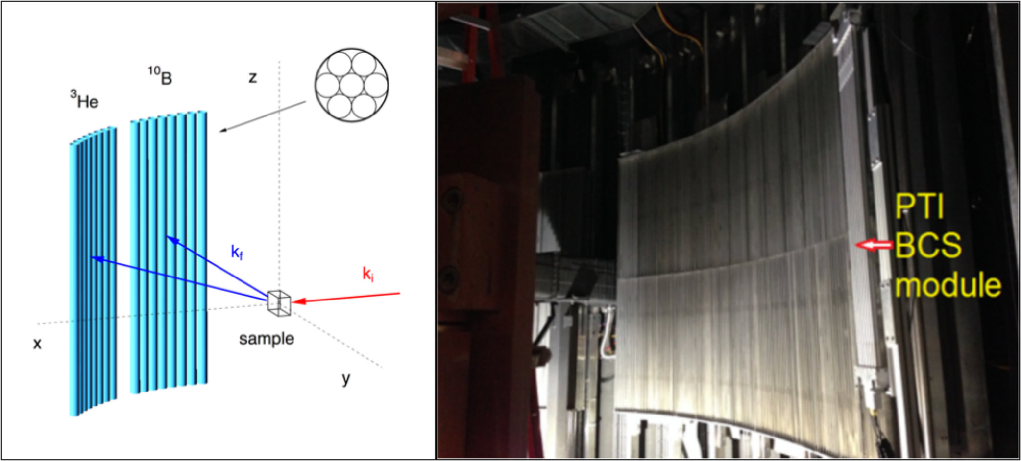 Figure 2
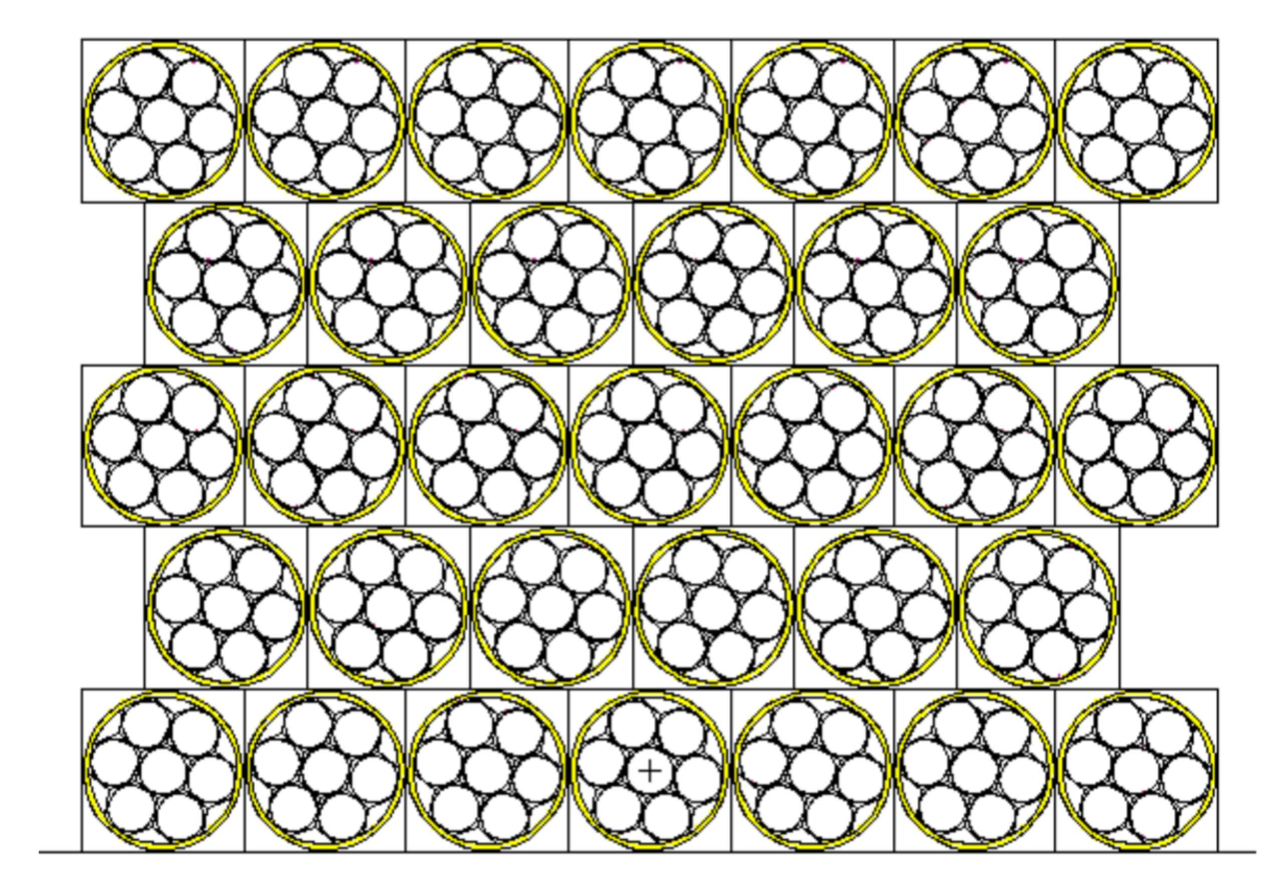 Figure 3
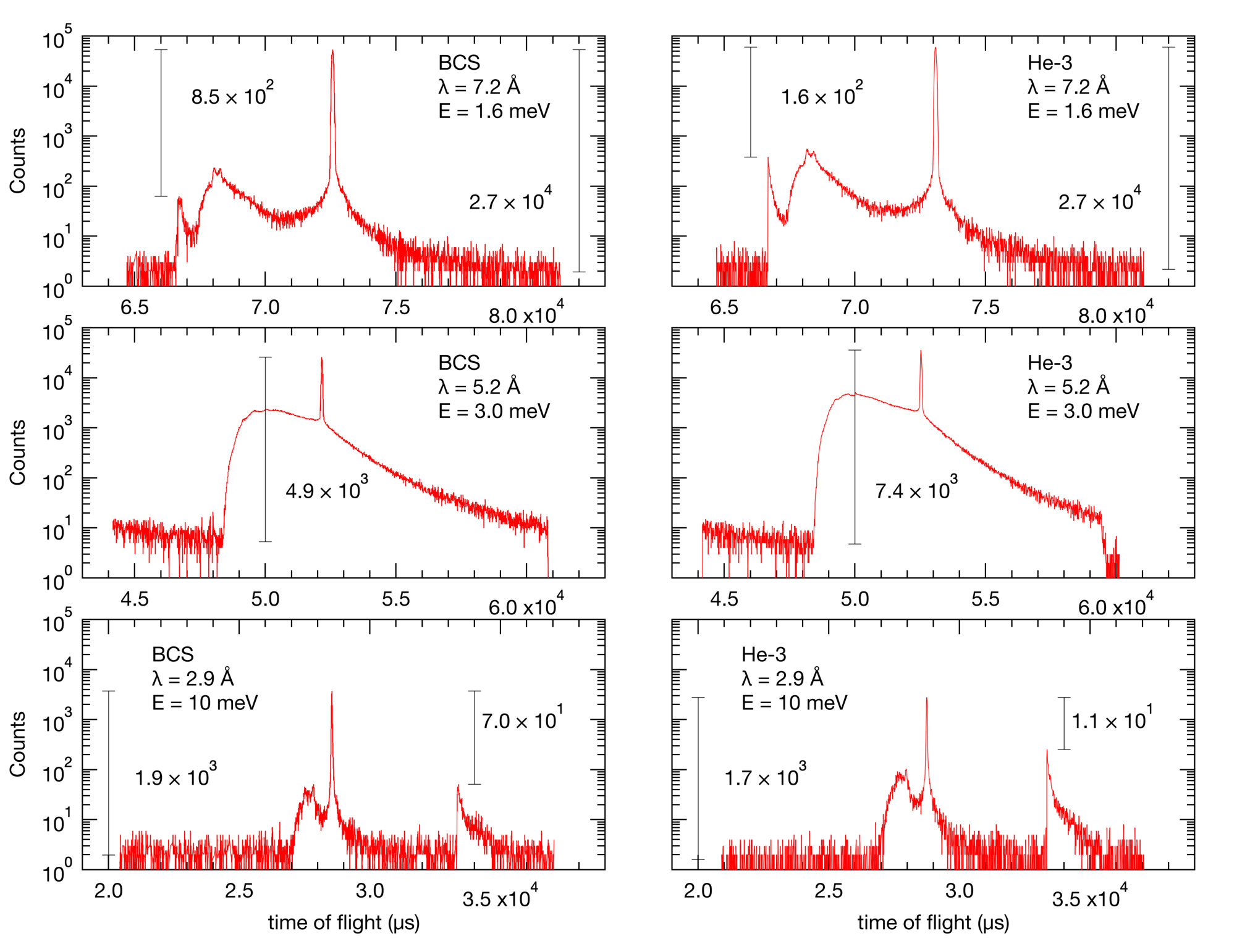 Figure 4
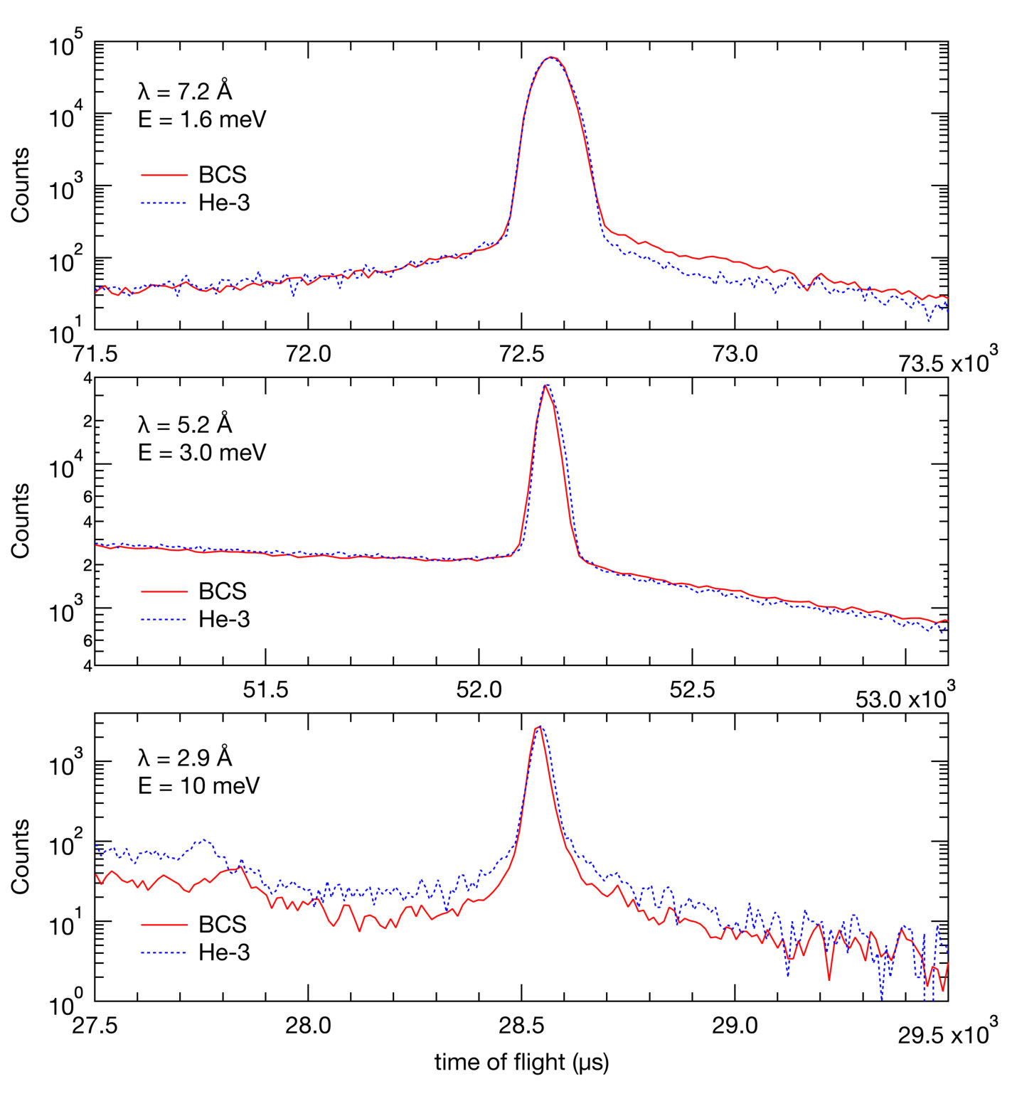 Figure 5
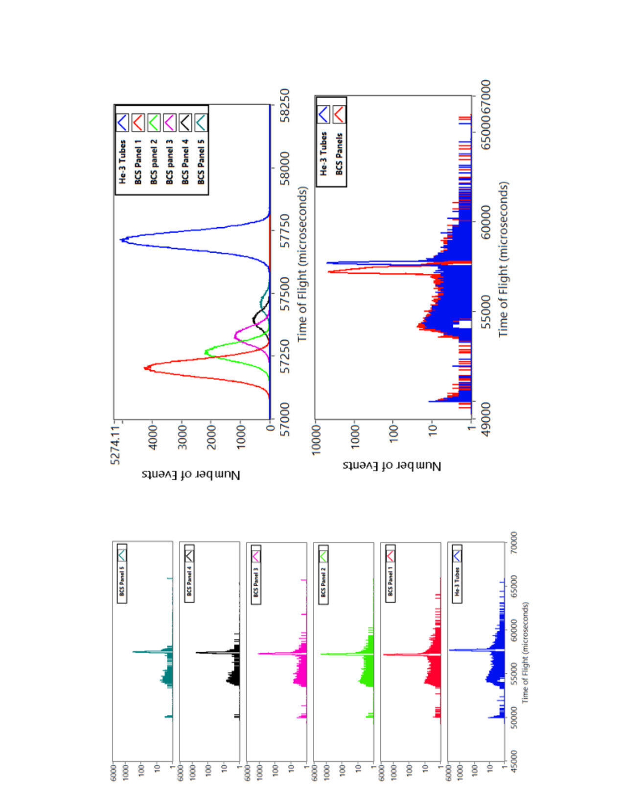 Figure 6
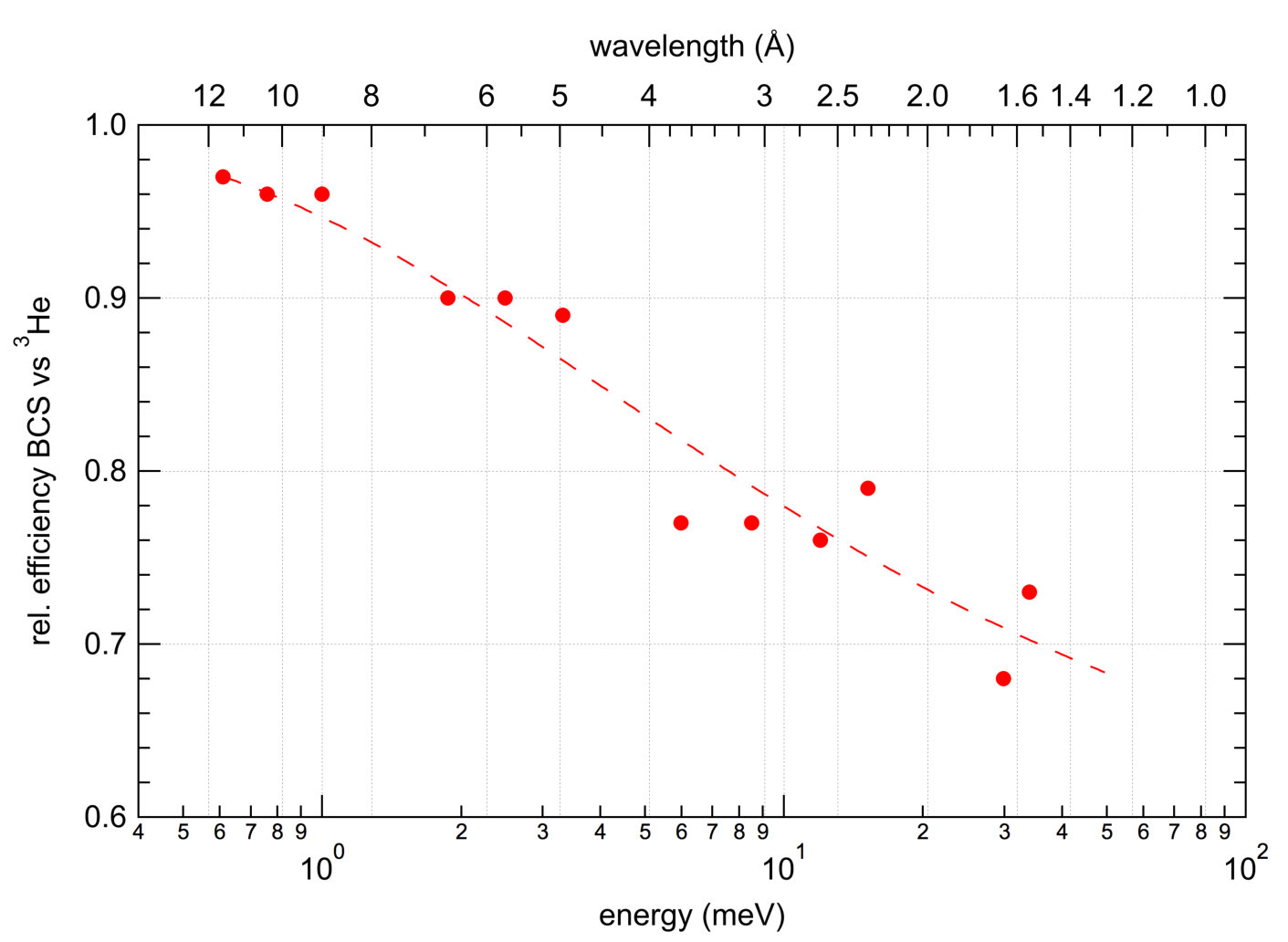 Figure 7
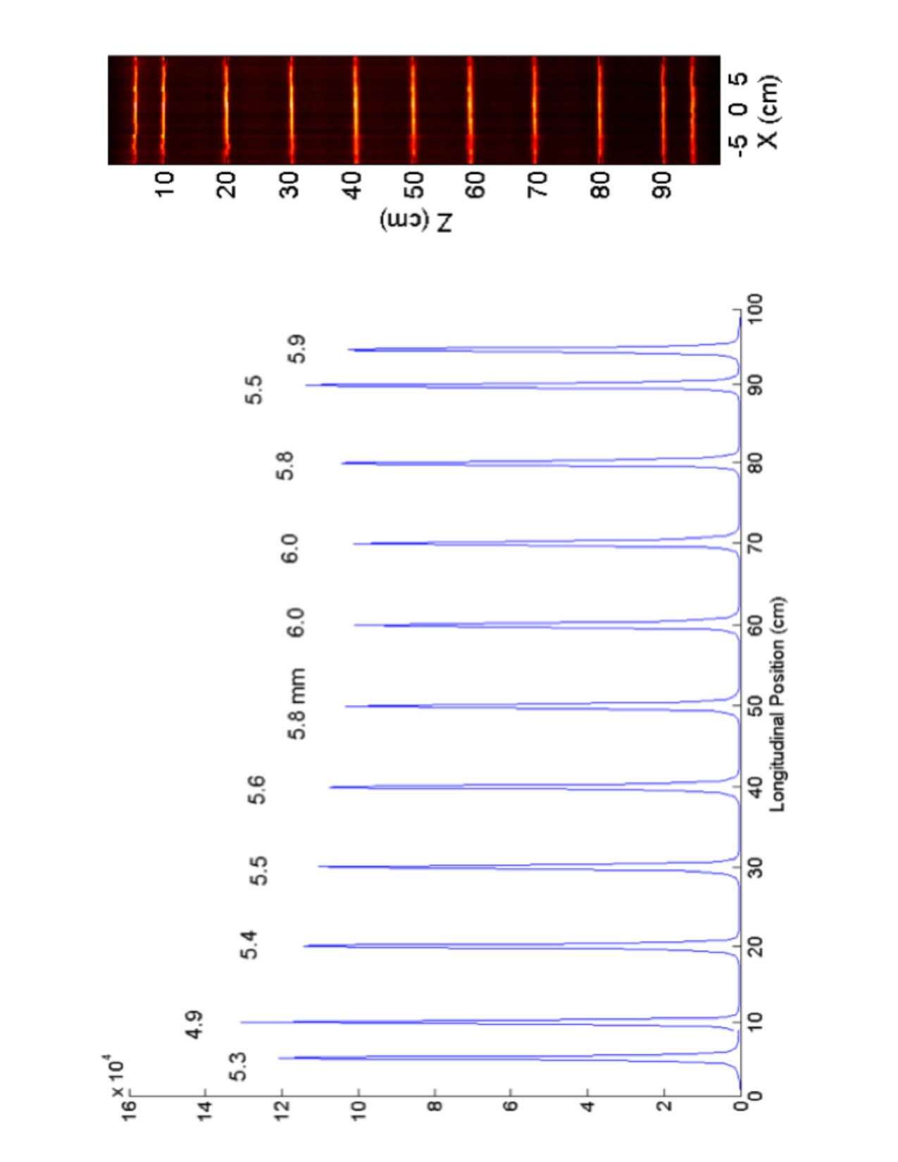 Figure 8
Peer Reviews
No public reviews on file for this paper yet. If you reviewed it on a platform where reviews are public (OpenReview, ICLR, NeurIPS, ICML), you can paste yours below so the community can read it here.
Videos
No videos yet. Explain this paper in a talk, walkthrough, or lecture? Add one.
Performance tests of boron-coated straw detectors with thermal and cold neutron beams
Georg Ehlers
Neutron Technologies Division, Oak Ridge National Laboratory, Oak Ridge, TN 37831-6466, USA
Athanasios Athanasiades, Liang Sun, Christopher S. Martin, Murari Regmi, Jeffrey L. Lacy
Proportional Technologies, Inc., 12233 Robin Blvd., Houston, TX 77045, USA
Abstract
Prototypes of newly developed boron-coated straw (BCS) detectors have been tested in the thermal and cold neutron energy ranges. Their neutron detection performance has been benchmarked against the industry standard (detector tubes filled with 3He gas). The tests show that the BCS straws perform near their theoretical limit regarding the detection efficiency, which is adequate for scientific instruments in the cold neutron energy range. The BCS detectors perform on par with 3He tubes in terms of signal to noise and timing resolution, and superior regarding longitudinal spatial resolution.
keywords:
neutron detection methods, neutron scattering, neutron spectroscopy
††journal: Nucl. Instrum. and Meth. in Physics Research A,myfootnotemyfootnotefootnotetext: This manuscript has been authored by UT-Battelle, LLC under Contract No. DE-AC05-00OR22725 with the U.S. Department of Energy. The United States Government retains and the publisher, by accepting the article for publication, acknowledges that the United States Government retains a non-exclusive, paid-up, irrevocable, world-wide license to publish or reproduce the published form of this manuscript, or allow others to do so, for United States Government purposes. The Department of Energy will provide public access to these results of federally sponsored research in accordance with the DOE Public Access Plan (http://energy.gov/downloads/doe-public-access-plan).
1 Introduction
Neutron scattering is a powerful experimental technique with a wide range of applications in hard and soft condensed matter physics, chemistry, biology, and materials science [1]. A number of international user facilities provide neutron beams for visiting researchers from government laboratories, academia, and industry, who perform thousands of scattering experiments every year [2, 3].
A critical component of every neutron scattering instrument is the neutron detection system. Neutron detectors based on pressurized 3He gas tubes are in common use: the grand total of 3He gas in present installations at various neutron sources world-wide exceeds 90,000 liters. The current global demand for 3He gas to use in new or upgraded neutron scattering instruments by far exceeds the available amount on the market [4].
The limited availability and high cost of 3He gas have motivated various development efforts for alternate detection technologies, with priority given to detection efficiency, spatial resolution, rate limit, cost, or any combination thereof [5, 6, 7, 8, 9, 10, 11, 12, 13, 14, 15]. The needs of various types of neutron scattering instruments also differ in these performance metrics. For example, while single crystal diffraction instruments need to take a locally high rate and should possess very good spatial resolution, spectroscopy instruments emphasize efficiency, low intrinsic background and low sensitivity to -radiation.
To address the worldwide shortage of 3He, Proportional Technologies, Inc. (PTI) has developed the boron coated straw (BCS) neutron detection technology [16]. A m thick 10B-enriched boron carbide (10B4C) layer is uniformly sputtered onto a Cu foil, which is then cut to size and spiral welded along the length to form a straw with mm diameter with the coating on the inside. BCS detectors are packed in groups of 7 inside sealed aluminum tubes. The tubes are 25.4 mm (1 inch) in diameter, with an active length of about 1 m, and allow sealed operation for indefinite periods of time. More details are given in section 2 below.
When compared with other replacements for 3He gas, the BCS technology provides benefits such as a direct drop-in replacement for 3He tubes, stability, a neutron detection efficiency near the theoretical limit, a high tolerance to temperature extremes and shock, and very good event rejection, resulting in an excellent signal to noise ratio. The readout electronics features a noise rejection algorithm which is essential to achieve proper resolution in the longitudinal direction of a tube.
2 Design and Fabrication Details
A single BCS detector contains a close-packed array of 7 thin walled, boron-coated copper tubes which are referred to as “straws”. The straws are 7.5 mm in diameter, coated on the inside with a thin layer of 10B-enriched boron carbide 10B4C. The 10B4C layer is sputter coated onto a thin copper foil, and reels of this coated foil are spiral welded into their straw shape via an automated process. This BCS technology relies on the 10B reaction:
[TABLE]
wherein 7Li and particles are emitted in opposite directions from the neutron absorption site with kinetic energies of 1.47 MeV and 0.84 MeV, respectively. For example, a 10B4C layer of 1 m thickness allows for one of the two charged particles to escape the layer 78% of the time, ionizing the gas inside the straw. Therefore, the detection efficiency of a dense array of straws approaches 78% at any desired wavelength as the number of layers increases.
The schematics in Fig. 1 shows how the 7 straws are close-packed in a single, sealed aluminum tube. The external tube is 25.4 mm in diameter, and can be up to 3.5 m long. Each tube is sealed using aluminum/ceramic end-caps, which allow for operation of the straw detectors in sealed mode. The detectors remain operational for indefinite periods of time in vacuum environments. One end-cap supports a gas port that allows for purging with the desired gas mixture to a pressure below 1 atm, after which the port is sealed.
The electronic readout of the detectors has been described in more detail elsewhere [17, 18]. Briefly, the 7-straw tubes are decoded by connecting the 7 front-end amplifier outputs together within each tube on one end to identify the tube index, (Fig. 1A), and by connecting each straw to each same-numbered neighbor on the other end to identify the straw index, (Fig. 1B). For a given neutron event, only one signal from each is larger than a pre-set threshold value, providing the identification of the specific firing straw. The longitudinal position of neutron interaction is measured using a charge division method.
The full readout scheme is modified from this simple description so that only one of the seven pre-amplifier outputs (at either end) containing the true neutron event is digitized, significantly reducing the readout hardware and increasing the count rate capability. This scheme is implemented by placing threshold discriminators (comparators) prior to the shaping circuitry, followed by non-retriggerable monostable multivibrators (one-shot) along with very fast very low resistance switch ICs, which open the appropriate gate to send only one of the seven with a signal to the Analog-Digital-Converter (ADC). A priority encoder is also implemented to transmit straw/tube ID to a buffer amplifier at either end which converts the code to one of seven pulse levels, subsequently digitized by another ADC. Since more than one switch can be turned on at once, control logic is designed to ensure that only one signal over threshold is selected. In addition, there is a latch to ensure that an over threshold signal arriving from other straws during the integration gate is prevented from causing the selector switches from changing. The readout block diagram is shown in Fig. 1C. Only four ADCs are required to read out a 7-tube group, a significant reduction in hardware cost.
3 Experimental Setup For Detector Testing
The Cold Neutron Chopper Spectrometer [19, 20] (CNCS) at the Spallation Neutron Source (SNS) in Oak Ridge provided the environment for most of the detector tests. CNCS delivers a monochromatic pulsed beam of cold or thermal neutrons to the sample. The neutron energy (wavelength) range covered in the tests was from 0.5 meV (13 Å) to 50 meV (1.3 Å). The source frequency at SNS is 60 Hz and the pulse length on the sample is variable, in the range s. The pulse length on sample and the wavelength can be freely adjusted with the instrumental chopper settings. CNCS features a large array of 2 m long position-sensitive 3He tubes which are arranged in an arc at m distance from the sample, covering about in the scattering plane from to . The tube diameter is 1 inch and the partial 3He pressure is 6 bar. Tubes are vertically centered in the scattering plane and arranged in panels holding 8 tubes each (“8-packs”). The tube walls are 0.5 mm stainless steel (SS-304). The separation between the tubes is mm to allow the placement of neutron absorbing fins between the tubes. In order to avoid parasitic air scattering, the detector array is located in a large enclosure that is filled with Ar gas at ambient pressure mixed with % of CO2.
The tests lasted several months and addressed the following: detection efficiency of the BCS prototype detector, timing resolution, signal peak to background ratio, and long term stability. The tests were conducted in parallel with normal instrument operation (primarily SNS user experiments).
Two BCS prototype detectors were tested at CNCS. The first was a single-layer panel consisting of seven 1 m long aluminum tubes with a diameter of 1 inch. This setup is shown in Fig. 2. Each BCS tube holds 7 straws as shown in the top center inset of Fig. 2. The 1-layer panel was centered vertically in the same way as the 3He tubes. The panel was mounted directly at the side of the last 8-pack of 3He tubes at a scattering angle of . The BCS tubes were located slightly closer to the sample (3.194 m) than the 3He tubes (3.478 m) of the nearest 8-pack, which was the one primarily used for performance comparisons. To this end, the absorbing fins between the 3He tubes were removed from this 8-pack. The back and sides of the 1-layer panel were shielded with neutron absorbing Cd. The CNCS 3He tubes also have such shields on the backend.
From October 2013 until May 2014, the 1-layer panel was operated for more than 2500 hours logging million events. Straw performance was totally reliable over the entire testing period with no observed degradation of performance in any of the 49 BCS detectors. The only problem encountered was leakage experienced in the external HV electrical boards at highest voltages due to the Argon/CO2 atmosphere employed in the instrument. This was remedied by appropriate conformal coating in the design of the second prototype.
The second prototype detector was a multi layer panel which was an arrangement of 33 tubes in 5 layers in a 7-6-7-6-7 arrangement (see Fig. 3). The main purpose of this second generation prototype was to achieve higher counting efficiency. This panel was tested from January to May 2016. As before, the panel was mounted right next to the last 8-pack of 3He tubes. The distances of the individual layers to the sample position were calibrated by neutron time-of-flight, see below. Similar neutron background shielding with Cd was used for this panel.
The 1-layer panel was also tested at the CG-1A beam line at the HFIR reactor at Oak Ridge. These tests focused primarily on the spatial resolution (longitudinally) of the individual tubes. A monochromatic beam with a wavelength of Å was used in these tests.
4 Results
4.1 General comparison
Time-of-flight spectra measured with the 1-layer BCS detector and the 3He tubes are shown in Fig. 4. These spectra show raw data binned in time-of-flight without any processing except time stamping. These measurements were made with different samples at different times. Therefore, the intensity scales in these plots cannot be directly compared. These spectra show convincingly several key properties of the BCS detectors, regarding:
the peak intensity relative to the apparent ambient background level 2. 2.
dynamic range 3. 3.
the elastic peak to flash pulse height ratio (see below)
The performance of a detector in these metrics is of great importance for a time of flight instrument. The ratio of the peak intensity to the apparent ambient background level is nearly the same for both detectors. The numbers are directly comparable because both detectors were shielded in the same way with Cd on the backend (see above). It has long been recognized that the low efficiency for radiation is one key property of detectors based on 3He. Spectra measured at 1.6 meV and 10 meV feature the flash pulse of high energy ( MeV) neutrons which is emitted by the source when the proton pulse hits the target. These neutrons propagate through many meters of shielding and arrive at the detector at virtually zero true time of flight which is why they occur at integer multiples of 16,666.7 s (after folding into the appropriate frame by the data acquisition software). The peak to flash pulse height ratio for the two detectors is nearly the same as well (the BCS detector actually performs better than the 3He tubes in this regard).
The spectra at the three energies were measured with different samples at different times. The intensity at 1 meV and 10 meV was rather low in absolute terms which is why the flash pulse is more prominently visible. The spectra at 3 meV were measured with a protonated soft hydrogenated material and contain strong inelastic scattering all the way to infinite energy gain (which occurs at s in this case).
The scattering around the elastic time of flight (“quasi-elastic scattering”) is often of particular importance. The occurrence of such scattering reveals the existence of dynamic modes in a material that are very slow on average or have a low energy scale (much lower than the energy of the neutron). Diffusive motions fall into this category (for example, of particles suspended in a liquid), or the relaxational dynamics of molecules of a viscous liquid. The two most important characteristics of an instrument for such studies are the energy resolution (width of the elastic line) and the instrument background level around the elastic line. Quasi-elastic scattering will be seen as a broadening of the elastic line or as an increase in scattering around it, or both. The sharper the elastic line and the lower the instrument background around it, the smaller the effects one can discern in a real material.
The datasets from Fig. 4 are again shown in Fig. 5, zooming into the range around the elastic time of flight. The 3 meV measurement is actually not particularly conclusive for the detector performance in this area because the sample was a strong scatterer in the quasi-elastic regime. However, both the 1.6 meV and the 10 meV measurements show that the BCS detector was on par with 3He tubes in this range. To help with the comparison, the BCS data were translated horizontally on the time axis to overlap with the 3He tube data.
Time-of-flight spectra measured with the 5-layer BCS detector and the 3He tubes are shown in Fig. 6. The five layers are separated out individually, and the position of the elastic time of flight peak indicates the different distances of the layers to the sample. One can also see how the layers count less and less indicating a shadowing effect, which is expected. It remains to be analyzed how much this matters for real neutron scattering applications. Another concern is the secondary scattering in the aluminum which matters at energies above the Bragg cut-off at 3.74 meV. Again, it will require more dedicated testing to investigate this issue. The pictures show that a depth of five active layers is about adequate for cold neutrons. Comparing time-of-flight spectra, in particular, the ratio of the count rate at the elastic line to the apparent time-independent background, reveal that the straw detector performs equally well (if not better) than the 3He tubes.
The next generation of straw detectors will address concerns of secondary scatter in detector materials by introducing design changes, to include straw walls made from high-purity aluminum, rather than copper, and containment tubes with a thinner wall of 0.25 mm. Initial production runs showed that boron could be successfully coated onto 25-m-thick aluminum foil; the coated foil was then formed into a straw, using the same spiral welding technique, with better results compared to the copper foil. At the same time, containment tubes employed in current production were successfully machined down to an outer diameter of 24.1 mm, from 25.4 mm (1.00 inch), reducing the wall thickness down to 0.25 mm (from 0.89 mm). The above design changes reduce the mass of detector materials by a factor of 3.5, with a corresponding reduction in scatter.
4.2 Counting Efficiency
One of the most important metrics for neutron scattering applications is the efficiency with which neutrons are detected. The performance of the BCS 5-layer detector against the 3He tubes is shown in Fig. 7. A vanadium standard sample was used in these measurements and only the elastic scattering was used for the analysis. The count rates in each detector were measured simultaneously, and were corrected for the detection solid angle in order to achieve a fair comparison. The efficiency is within 10% of expected values calculated by MCNP code.
4.3 Longitudinal Spatial Resolution
For these tests the 1-layer panel was translated vertically behind a 1 mm wide slit that was made of neutron absorbing material. The main result is shown in Fig. 8. Measurements were taken at 11 longitudinal locations (5 cm, 10 cm, 20 cm, 30 cm, 40 cm, 50 cm, 60 cm, 70 cm, 80 cm, 90 cm and 95 cm). Data were collected continuously during the full translation at each longitudinal location. Fig. 8 shows longitudinal resolution at 11 locations as well as a reconstructed image using a superposition of all collected data. The resolution is mm full width at half maximum (FWHM) and is quite uniform along the length excluding small regions at the ends of the tubes of less than 5 cm. The noise rejection in the readout electronics is essential to achieve this resolution.
5 Conclusion
Prototypes of newly developed boron-coated straw detectors have been tested in a cold neutron beam. Their performance has been benchmarked against the industry standard of detector tubes filled with 3He gas. The tests show that the BCS detectors perform on par with 3He tubes in terms of signal to noise ratio and timing resolution. They are better than 3He tubes regarding spatial resolution both in the longitudinal direction and horizontally (because of the smaller diameter of the straws). Regarding the detection efficiency of cold neutrons, the BCS straws are near their theoretical limit, and perform adequately in the cold neutron energy range.
6 Acknowledgments
We would like to thank Rick Riedel for his support of the tests at HFIR, and Jana Olson for critical reading and comments. This work was supported by the U.S. Department of Energy (DOE), under SBIR Award No. DE-SC0009615. A portion of this research used resources at the High Flux Isotope Reactor and the Spallation Neutron Source, which are DOE Office of Science User Facilities operated by the Oak Ridge National Laboratory.
The reference list from the paper itself. Each links out to its DOI / PubMed record.
- 1[1] T. E. Mason, D. Abernathy, I. Anderson, J. Ankner, T. Egami, G. Ehlers, A. Ekkebus, G. Granroth, M. Hagen, K. Herwig, J. Hodges, C. Hoffmann, C. Horak, L. Horton, F. Klose, J. Larese, A. Mesecar, D. Myles, J. Neuefeind, M. Ohl, C. Tulk, X. L. Wang, J. Zhao, The Spallation Neutron Source in Oak Ridge: A powerful tool for materials research, Phys. B (Amsterdam, Neth.) 385-386 (Pt. 2) (2006) 955–960.
- 2[2] ILL Annual Report ar Xiv:https://www.ill.eu/about-the-ill/documentation/annual-report/ . URL https://www.ill.eu/about-the-ill/documentation/annual-report/
- 3[3] NIST Center For Neutron Research, 2018 Accomplishments And Opportunities ar Xiv:https://nvlpubs.nist.gov/nistpubs/Special Publications/NIST.SP.1231.pdf . URL https://nvlpubs.nist.gov/nistpubs/Special Publications/NIST.SP.1231.pdf
- 4[4] K. Zeitelhack, Search for alternative techniques to helium-3 based detectors for neutron scattering applications, Neutron News 23 (4) (2012) 10–13.
- 5[5] K. Tsorbatzoglou, R. D. Mc Keag, Novel and efficient 10B lined tubelet detector as a replacement for 3He neutron proportional counters , Nuclear Instruments and Methods in Physics Research Section A: Accelerators, Spectrometers, Detectors and Associated Equipment 652 (1) (2011) 381 – 383, symposium on Radiation Measurements and Applications (SORMA) {XII} 2010. doi:http://dx.doi.org/10.1016/j.nima.2010.08.102 . URL http://www.sciencedirect.com/science/article/pii/S 0168900210018899 · doi ↗
- 6[6] S. L. Bellinger, R. G. Fronk, W. J. Mc Neil, T. J. Sobering, D. S. Mc Gregor, Enhanced variant designs and characteristics of the microstructured solid-state neutron detector , Nuclear Instruments and Methods in Physics Research Section A: Accelerators, Spectrometers, Detectors and Associated Equipment 652 (1) (2011) 387 – 391, symposium on Radiation Measurements and Applications (SORMA) {XII} 2010. doi:http://dx.doi.org/10.1016/j.nima.2010.08.049 . URL http://www.sciencedirect.com/ · doi ↗
- 7[7] T. Bigault, J. Birch, J. C. Buffet, J. Correa, R. Hall-Wilton, L. Hultman, C. Höglund, B. Guérard, A. Khaplanov, F. Piscitelli, P. V. Esch, 10B multi-grid proportional gas counters for large area thermal neutron detectors , Neutron News 23 (4) (2012) 20–25. ar Xiv:http://dx.doi.org/10.1080/10448632.2012.725329 , doi:10.1080/10448632.2012.725329 . URL http://dx.doi.org/10.1080/10448632.2012.725329 · doi ↗
- 8[8] N. J. Rhodes, Scintillation detectors , Neutron News 23 (4) (2012) 26–30. ar Xiv:http://dx.doi.org/10.1080/10448632.2012.725331 , doi:10.1080/10448632.2012.725331 . URL http://dx.doi.org/10.1080/10448632.2012.725331 · doi ↗