Status of the Large Size Telescopes of the Cherenkov Telescope Array
Juan Cortina (for the CTA LST project)
TL;DR
This paper reviews the development, installation, and commissioning of the Large Size Telescopes for the Cherenkov Telescope Array, highlighting their design, capabilities, and initial performance results.
Contribution
It provides an update on the status, technical specifications, and first commissioning results of the LSTs in the CTA project, a major advancement in gamma-ray astronomy infrastructure.
Findings
First LST installed at CTA-North in 2018
LSTs can reposition within 20 seconds for GRB follow-up
Initial commissioning tests show promising performance
Abstract
The Cherenkov Telescope Array (CTA) will consist of two arrays of Imaging Atmospheric Cherenkov Telescopes (IACTs) at the northern and southern hemispheres. CTA will feature IACTs with mirrors of three different sizes optimized to cover different energy ranges. The proposed sub-arrays of four Large Size Telescopes (LST) at CTA-North and CTA-South target the lowest energy range between around 20 GeV and 100 GeV. Thanks to their low weight of around 110 tons the LSTs can move by 180 deg in azimuth in 20 seconds for Gamma Ray Burst (GRB) follow-up. An LST has a tessellated parabolic mirror of 23 m diameter equipped with a system of actuators to correct for gravity-induced deformations during data taking. Its low-weight 2 ton camera at the prime focus has a 4.5 deg diameter, 1855 high QE PMTs and an embedded readout with 1 GSps sampling speed designed for data acquisition rates exceeding 10…
Click any figure to enlarge with its caption.
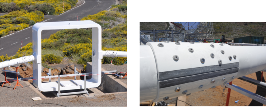 Figure 1
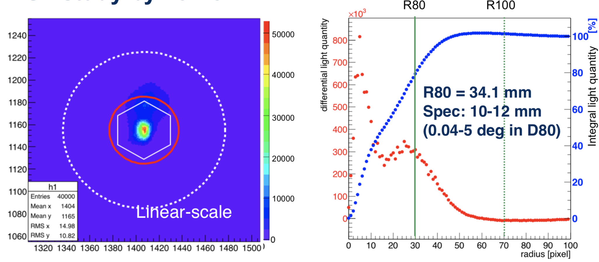 Figure 2
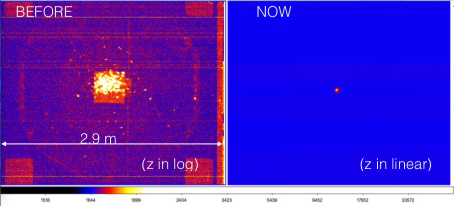 Figure 3
 Figure 4
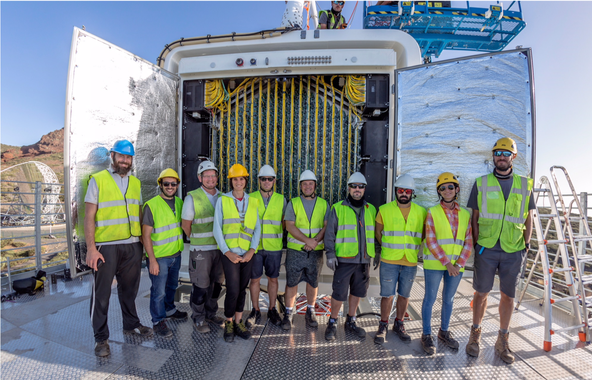 Figure 5
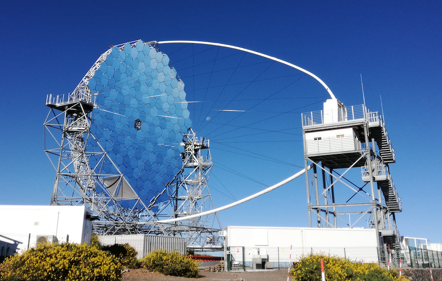 Figure 6
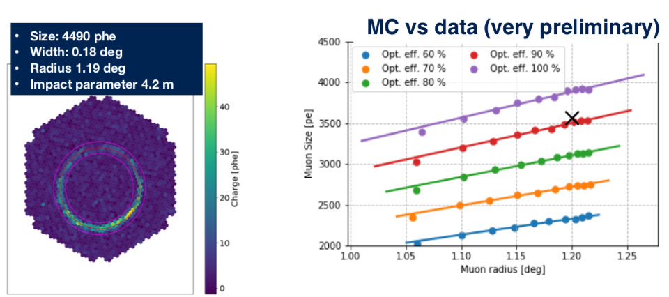 Figure 7
| Optical Parameters | |||
|---|---|---|---|
| Reflector type | 1-mirror, parabolic | ||
| Focal length | 28 m | ||
| Dish diameter | 23 m | ||
| f/D | 1.2 | ||
| Mirror area | 396 m2 | w/o shadowing | |
| Mirror effective area | 368 m2 | Including shadowing | |
| Preliminary on-axis PSF | 0.05∘ | ||
| Preliminary off-axis PSF | 0.11∘ | at 1∘ off-axis | |
| Preliminary tracking accuracy | 20 arcsec | RMS, online precision | |
| Pointing accuracy | 14 arcsec | RMS, post-calibration | |
| Camera Parameters | |||
| Camera dimensions (LxHxW) | 2.8 m x 2.9 m x 1.15 m | ||
| Weight | 2000 kg | ||
| Number of pixels | 1855 | ||
| Pixel linear size | 50 mm, incl light concentrator | 1.5 inch PMT | |
| Pixel field of view | 0.1∘ | ||
| Camera field of view | 4.5∘ | ||
| Trigger region field of view | 4.5∘ | ||
| Sampling speed | 1 GS/s | ||
| Analogue buffer length | 4 s | for hardware stereo trigger | |
| Readout rate | 7.5 kHz (required) 15 kHz (goal) | ||
| Dead time | 5% at 7.5 kHz | ||
| Mechanical parameters | |||
| Total weight | 103 tons | sum of moving parts | |
| Repositioning speed | 20 s | for 180∘ in azimuth | |
| Zenith drive range | 0∘ to 95∘ | ||
| Azimuth drive range | 408∘ | ||
| Inertia elevation | 6000 tonsm2 | ||
| Inertia azimuth | 12000 tonsm2 | ||
| Park position | zenith angle 95∘ | locked at the camera tower | |
| Height at Camera Access | 13 m above ground | In the parking position | |
Peer Reviews
No public reviews on file for this paper yet. If you reviewed it on a platform where reviews are public (OpenReview, ICLR, NeurIPS, ICML), you can paste yours below so the community can read it here.
Videos
No videos yet. Explain this paper in a talk, walkthrough, or lecture? Add one.
Taxonomy
TopicsAstrophysics and Cosmic Phenomena · Gamma-ray bursts and supernovae · Planetary Science and Exploration
Status of the Large Size Telescopes of the Cherenkov Telescope Array
for the CTA LST project111for consortium list see PoS(ICRC2019)1177
CIEMAT, Avda. Complutense 40, Madrid E-28040 Spain
Abstract:
The Cherenkov Telescope Array (CTA) will consist of two arrays of Imaging Atmospheric Cherenkov Telescopes (IACTs) at the northern and southern hemispheres. CTA will feature IACTs with mirrors of three different sizes optimized to cover different energy ranges. The proposed sub-arrays of four Large Size Telescopes (LST) at CTA-North and CTA-South target the lowest energy range between 20 GeV and 100 GeV. Thanks to their low weight of 110 tons the LSTs can move by 180 deg in azimuth in 20 seconds for Gamma Ray Burst (GRB) follow-up. An LST has a tessellated parabolic mirror of 23 m diameter equipped with a system of actuators to correct for gravity-induced deformations during data taking. Its low-weight 2 ton camera at the prime focus has a 4.5 deg diameter, 1855 high QE PMTs and an embedded readout with 1 GSps sampling speed designed for data acquisition rates exceeding 10 kHz. A fully equipped LST has been installed at the CTA-North site in 2018 and is expected to be finished commissioning during 2019. The remaining three LSTs in the north will be installed by 2022. We will review the status of the LSTs, describe the installation of the first LST and report on the first results of the commissioning tests.
1 Introduction
CTA[1] will consist of two arrays of IACTs at the northern and southern hemispheres. The IATCs will have mirrors of three different sizes optimised for different energy ranges. The proposed sub-arrays of four Large Size Telescopes (LST) at CTA-North and CTA-South feature the largest reflectors and target the lowest energies down to a threshold energy of 20 GeV. Major physics drivers in the LST energy range are transients, both galactic and extragalactic, pulsars and studies of the Extragalactic Background Light. The design grants special attention to the study of GRBs: the telescope has a very low weight to allow repointing by 180*∘* in less than 20 seconds so as to detect the GRB prompt emission.
The team within CTA responsible for the development of the LST consists of more than 100 scientists from nine countries: Brazil, Croatia, France, Germany, India, Italy, Japan, Spain and Sweden222see a full institution list at http://www.lst1.iac.es/collaboration.html. This team completed the design of the telescope in 2015. Development of the LST is different compared to the other CTA telescopes because the first LST (LST1) constructed is also a prototype. However, this prototype will be fully functional, and once commissioning finishes and verification tests are successfully completed, demonstrating the LST fulfils all CTA requirements, LST1 will become the first production LST of CTA. This decision is motivated by the relatively small number of units to be produced and the elevated cost of each individual telescope. If during commissioning it is found that design modifications are needed, the first telescope will be retrofitted to ensure its performance is equal to that of the other LSTs.
The second telescope will mark the beginning of the LST Construction phase. Several elements manufactured in workshops of participating institutes for LST1 will be subcontracted to industrial partners. Orders will be timed based on the experience obtained during the construction of LST1, aiming for a peak construction rate of two telescopes per year.
The LST1 construction started at the CTA-North site with infrastructure and permission application in 2015. The foundation was built between July 2016 and January 2017. The telescope itself was erected within 15 months between July 2017 and September 2018, ending with the official inauguration of the telescope on October 10, 2018. Figure 1 shows a picture of the telescope.
The reader is referred to the Technical Design Report (TDR) of the LST for a detailed description of the telescope and its component parts [2]. The LST’s main parameters are summarized in Table 1. The TDR also describes many of the tests that have been performed on the components of LST1 before installation in La Palma.
2 Infrastructure
The LST1 foundation withstands all the loads transmitted by the bogies and the central axis in order to keep in place the telescope in any kind of situation. It is a circular construction made of concrete and iron bar armature. The foundation of the remaining telescopes will have a very similar design but it must be dimensioned for the actual sites of the observatory and for the specific conditions of the soil at the position of each telescope especially at the CTA-South site. A circular rail of 23.9 m diameter and 500 mm width is fixed to the foundation by means of a pedestal, a curved I-beam. The steel feet are fixed with nuts to the concrete using special dowels that hold the required uplift forces.
Much of the basic infrastructure is currently installed in containers inside the fenced area: an energy container equipped with two flywheels that deliver power to the telescope drive during fast repositioning, a drive container with drive control electronics, an IT container that is equipped with enough computing power for the whole CTA-North and space for most of the control computers and an office container where operators can control the telescope and monitor its status. Some of this infrastructure will be relocated to the CTA-North operations building, which should be finished in 2022. The remaining LSTs will only be equipped with a drive and an energy container.
3 Telescope structure and drive system
The lower structure of the LST is made of steel tubes; the dish structure is a space-frame of carbon-fiber reinforced plastic (CFRP), steel and aluminium tubes. The lower structure rests on six wheel bogies running on the rail.
The baseline design of the camera support structure (CSS) is based on an almost parabolic arch geometry, reinforced along its orthogonal projection by two symmetric sets of fixed headstays. Most of its elements make use of CFRP, which is well known to provide a very high performance to mass ratio. On top of the CSS a square camera frame holds the camera at the focal distance. Figure 2 shows the camera frame and one of the CSS junctions.
To facilitate camera maintenance an access tower is permanently installed at the telescope parking position. The camera is accessed from a flat platform on top of the access tower.
The fast and precise movement of the LST is achieved by using electric servomotors on both the elevation and azimuth axis. Four synchronised motors are used for the azimuth axis and two for the elevation one. There are two main strategies depending on the operational mode: fast motion or tracking. In fast motion, a regulation method limiting the torque is used in order to ensure a good load distribution between the motors. While in tracking mode the speed and not the torque of the motors is limited. The azimuth and elevation motors are located on the top of the bogies and on the elevation drive arch, respectively.
The park in/out of the telescope including access tower clamping and moving platform is being automatized. More than 100 park in/out operations have been already performed. The telescope moves already to target and starts tracking successfully. The drive accuracy with respect to the rotation axis encoders is well below 30 arcsec. Fast repositioning tests were performed in Spring 2019. The tests fully validated the 20s goal for 180 degrees in azimuth. Drive speed regulation worked as expected and the feedback from the mechanics showed no issue. The emergency stops were successfully tested.
4 Optics and active mirror control
The optical system of the LST is an active optics system that includes a large parabolic reflector equipped with an active mirror control system (AMS) and a flat focal surface. The optical reflector is composed of 198 hexagonal mirrors each with an area of 2 m2. The mirrors are manufactured using the cold slump technique with a sandwich structure consisting of a soda-lime glass sheet, an aluminum honeycomb box and another glass sheet. The mirror box is made of stainless-steel. Each mirror weighs about 47 kg. The absolute mirror reflectivity between 300 nm and 550 nm is higher than 85%. The optical PSF containment diameter () of a single facet is less than 1/3 of a pixel size at the centre of the Camera.
The mirrors are attached to the dish of the LST structure using two actuators and a fixed point. The actuators have accurate step motors (5 m step size) which are controlled by the AMC program to achieve the required optical performance at any moment of time. Each mirror facet has a small CMOS camera attached that observes a fixed-point (generated by a laser) on the Camera plane, and the position of the fixed-point is used as a reference to correct any misalignment of the mirrors. This active optics positioning will be done online with a frequency of 0.1 Hz.
16 ”AMC boxes” provide power to the actuators. The actuators are controlled by a standard industry PC installed in the AMC box. One box is responsible for 13 facets (26 actuators) at maximum. The 16 boxes are installed in the space frame of the telescope. The AMC software consists of two layers: a slave program controls each of the AMC boxes while a master OPCUA server controls the whole reflector. A master and a slave GUI have been developed.
First runs of the mirror adjustment process were completed: mirrors were adjusted group by group on the shutter of the camera while the so-called star imaging screen (SIS) right in front of the pixels was still unavailable. Mirrors were also adjusted one by one on the shutter, with an automatic image recognition. Outliers were easily recognised and manually brought to the center of the PSF. 80% of the light is already focused within a radius of 34.1 mm (see figure 3). We believe that the final goal of 10 mm can be accomplished once the final focus is performed.
The remaining hardware to complete the subsystem to determine the absolute pointing of the telescope (reference laser for the AMC and starguider camera) will be installed in Summer 2019 [4].
5 Camera
The camera of the LST has a weight of less than 2 tonnes and is equipped with 265 PMT modules that are easy to access and maintain. Each module has 7 channels. Hamamatsu photomultiplier tubes with a peak quantum efficiency of 42% (R11920-100) are used as photosensors. Each photosensor is equipped with an optical light concentrator. The camera has been designed for maximum compactness and lowest weight, cost and power consumption while keeping optimal performance at low energies.
Each pixel incorporates a photosensor as well as the corresponding readout and trigger electronics. This readout electronics is based on the DRS4 chip. In order to increase the analogue buffer length, 4 DRS4 channels are cascaded. The analogue signals are split into Low and High gains. The camera trigger strategy is flexible and based on the shower topology and the temporal evolution of the Cherenkov signal produced in the camera. The analogue signals from the photosensors are conditioned and processed by dedicated algorithms that look for extremely short and compact light flashes. Furthermore, the cameras are interconnected in order to form an on-line coincidence trigger amongst the LSTs. This enables the suppression of accidental triggers by up to a factor of 100.
Manufacturing and assembly of the camera mechanics and electronics took several years mainly at institutes in Japan and Spain (find details on some of the characterisation results in [5].). The mechanics were later assembled at the lab with the electronics and went through a round of exhaustive tests. The camera and PMT modules were transported separately to La Palma, where they were re-integrated and tested again. The final installation into the camera frame took only a few days in September 2018. Figure 4 shows the camera right after installation.
During the last months the environmental variables inside the camera have remained within specifications both night and day. Many of the camera calibration procedures have been completed: trigger timing and PPS signal propagation, and High Voltage flat fielding. The calibration of the trigger L0 settings (clipping, delay, attenuation) and L1 thresholds is ongoing.
Data taking runs on calibration light pulses and cosmic ray showers have been successfully taken. As an illustration figure 5, left, shows an event with a complete muon ring. The charge and radius of the muon ring can actually be used to calibrate both the optical efficiency of the telescope and the optical PSF. The right panel of the same figure shows how this specific muon ring would fit with the MC predictions.
The camera is calibrated with a 355 nm laser located at the center of the mirror dish. The laser was installed last year and is operational. Details can be found in [3].
A periodic trigger up to 18.8 kHz (with fixed gain selection) was reached. The rate is limited to 12 kHz without gain selection. For random triggers the highest possible rate so far is 11.5 kHz, probably limited by TCP/IP congestion. This limit is under investigation.
6 Outlook
We expect to complete the commissioning of LST1 before the end of 2019. Observations with the telescope could then start although the performance of a single LST is significantly worse than the performance of the LST sub-array or the whole CTA-North. The plans to complete the four LSTs at the CTA North site are firm. The schedule of the production follows the funding flow in the countries with responsibilities in the LST project. A good fraction of the components is already available, others are under production. Installation of the telescopes is targeted before the end of 2022 and commissioning during will take place during the next year.
Acknowledgments
This paper has gone through internal review by the CTA Consortium.
This work was conducted in the context of the CTA LST Project.
We gratefully acknowledge financial support from the agencies and organizations listed here: http://www.cta-observatory.org/consortium$\_$acknowledgments
The reference list from the paper itself. Each links out to its DOI / PubMed record.
- 1[1] D. Mazin for the CTA consortium, Status of the Cherenkov Telescope Array , these proceedings.
- 2[2] LST team for the CTA consortium, Large Size Telescope Technical Design Report , available at http://www.lst 1.iac.es/index.html
- 3[3] M. Palatiello for the CTA consortium, Performances of the Camera Calibration System for Large Size Telescope these proceedings.
- 4[4] D. Zaric for the CTA consortium, Pointing System for the Large Size Telescopes Prototype of the Cherenkov Telescope Array these proceedings.
- 5[5] S. Sakurai for the CTA consortium, The calibrations of the first Large-Sized Telescope of the Cherenkov Telescope Array these proceedings.