Theory of Spin Injection in Two-dimensional Metals with Proximity-Induced Spin-Orbit Coupling
Yu-Hsuan Lin, Chunli Huang, Manuel Offidani, Aires Ferreira, and, Miguel A. Cazalilla

TL;DR
This paper develops a comprehensive theory for spin injection and coupled spin-charge transport in two-dimensional materials with proximity-induced spin-orbit coupling, accounting for uniform and random SOC components.
Contribution
It introduces a realistic model of spin-charge diffusion in 2D systems with proximity-induced SOC, including various charge-to-spin conversion mechanisms and their experimental signatures.
Findings
Dominant spin-charge conversion mechanisms can be identified via nonlocal resistance measurements.
The theory applies to 2D electron gases in heterostructures with adatoms and imperfections.
Analysis helps distinguish between different spin-orbit coupling effects in experiments.
Abstract
Spin injection is a powerful experimental probe into a wealth of nonequilibrium spin-dependent phenomena displayed by materials with spin-orbit coupling (SOC). Here, we develop a theory of coupled spin-charge diffusive transport in two-dimensional spin-valve devices. The theory describes a realistic proximity-induced SOC with both spatially uniform and random components of the SOC due to adatoms and imperfections, and applies to the two dimensional electron gases found in two-dimensional materials and van der Walls heterostructures. The various charge-to-spin conversion mechanisms known to be present in diffusive metals, including the spin Hall effect and several mechanisms contributing current-induced spin polarization are accounted for. Our analysis shows that the dominant conversion mechanisms can be discerned by analyzing the nonlocal resistance of the spin-valve for different…
Click any figure to enlarge with its caption.
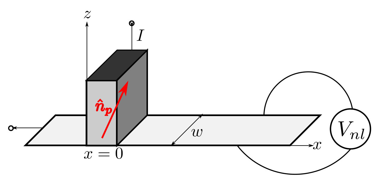 Figure 1
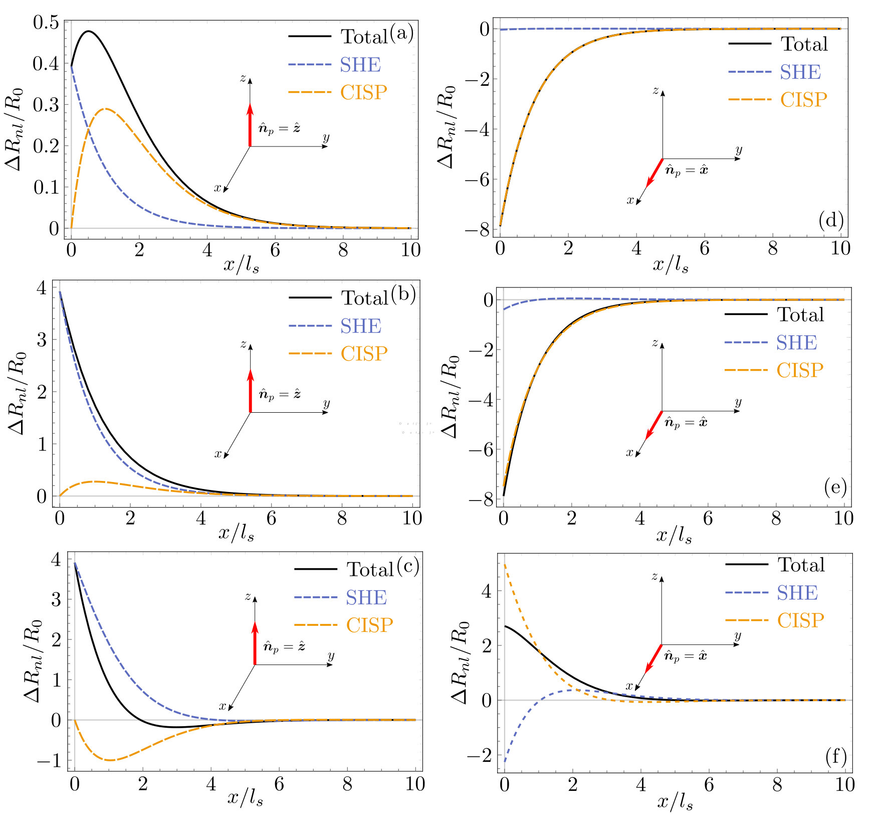 Figure 2
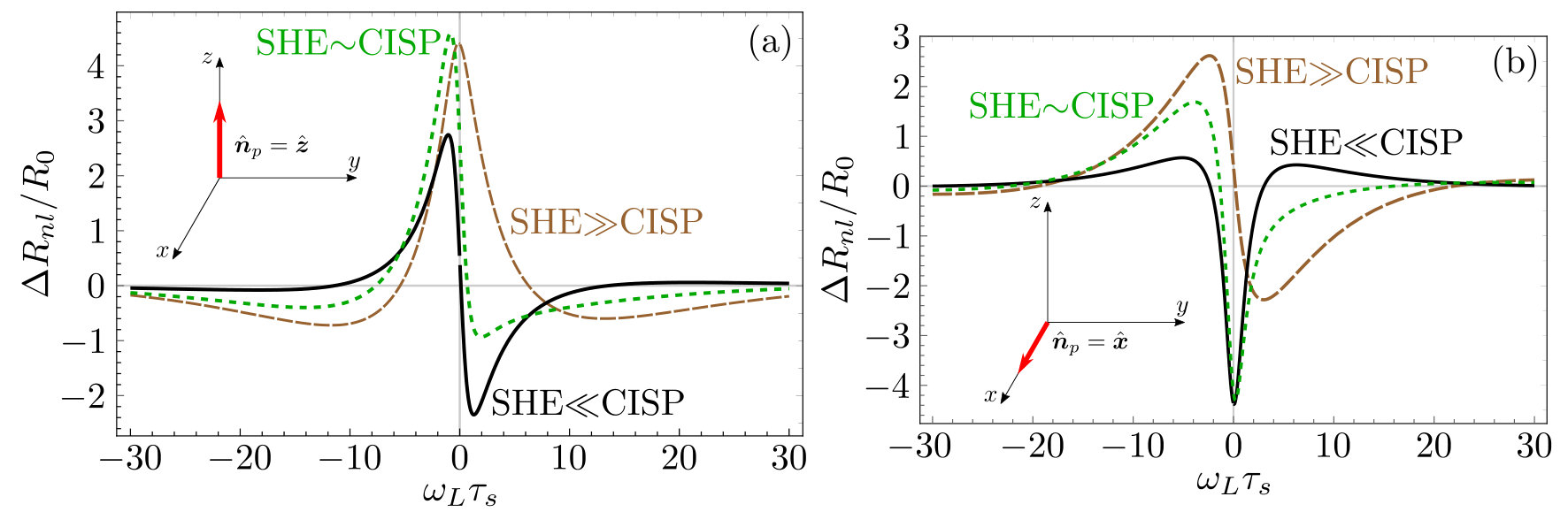 Figure 3
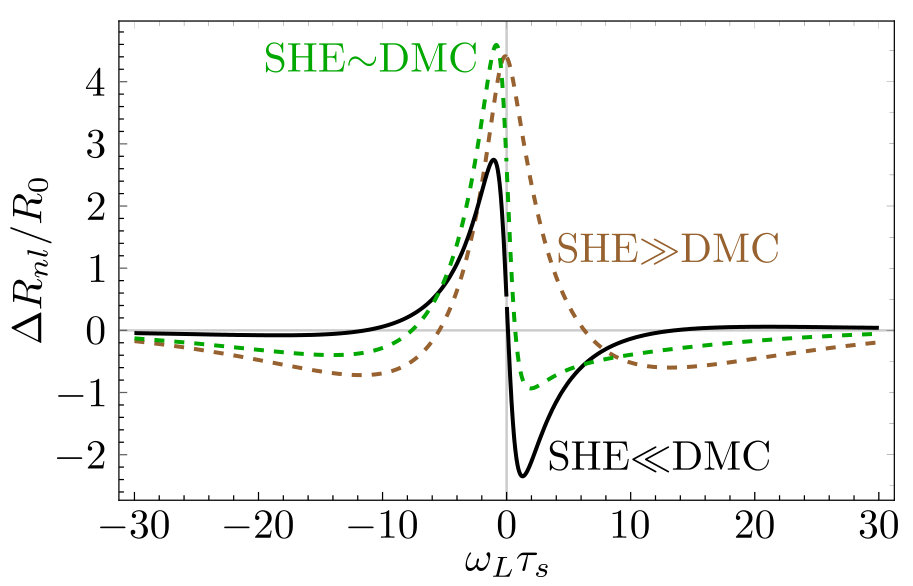 Figure 4
 Figure 5
Peer Reviews
No public reviews on file for this paper yet. If you reviewed it on a platform where reviews are public (OpenReview, ICLR, NeurIPS, ICML), you can paste yours below so the community can read it here.
Videos
No videos yet. Explain this paper in a talk, walkthrough, or lecture? Add one.
Theory of Spin Injection in Two-dimensional Metals
with Proximity-Induced Spin-Orbit Coupling
Yu-Hsuan Lin
Department of Physics, National Tsing Hua University, Hsinchu 30013, Taiwan
Chunli Huang
Department of Physics, The University of Texas at Austin, Austin, Texas 78712,USA
National Center for Theoretical Sciences (NCTS), Hsinchu 30013, Taiwan
Manuel Offidani
University of York, Department of Physics, YO10 5DD, York, United Kingdom
Aires Ferreira
University of York, Department of Physics, YO10 5DD, York, United Kingdom
Miguel A. Cazalilla
Department of Physics, National Tsing Hua University, Hsinchu 30013, Taiwan
National Center for Theoretical Sciences (NCTS), Hsinchu 30013, Taiwan
Donostia International Physics Center (DIPC), Manuel de Lardizabal, 4. 20018 Donostia-San Sebastian, Spain
Abstract
Spin injection is a powerful experimental probe into a wealth of nonequilibrium spin-dependent phenomena displayed by materials with spin-orbit coupling (SOC). Here, we develop a theory of coupled spin-charge diffusive transport in two-dimensional spin-valve devices. The theory describes a realistic proximity-induced SOC with both spatially uniform and random components of the SOC due to adatoms and imperfections, and applies to the two dimensional electron gases found in two-dimensional materials and van der Walls heterostructures. The various charge-to-spin conversion mechanisms known to be present in diffusive metals, including the spin Hall effect and several mechanisms contributing current-induced spin polarization are accounted for. Our analysis shows that the dominant conversion mechanisms can be discerned by analyzing the nonlocal resistance of the spin-valve for different polarizations of the injected spins and as a function of the applied in-plane magnetic field.
Layer-by-layer assembly of atomically thin crystals has provided a unique platform to realize emergent phenomena in two dimensional electron systems (Geim_Nature2013, ). Examples range from secondary Dirac points and Hofstadter’s butterfly in Moir superlattices (VDW_Yankowitz_12, ; VDW_Ponomarenko13, ; VDW_Dean_13, ) to superconductivity in twisted bilayer graphene (VDW_Cao_18, ; VDW_Yankowitz19, ) and long-lived excitons in heterobilayers made from semiconducting two-dimensional (2D) crystals (VDW_Rivera_15, ).
The engineering of the electronic properties, and in particular, the strength of spin-orbit coupling (SOC) in layered materials is facilitated by the weak van der Waals bonding that allows the stacking of two-dimensional (2D) crystals with precise interlayer registry (VDW_Review_Yankowitz_19, ). Indeed, several approaches can be used to enhance and control SOC in the two-dimensional electron gases formed at the atomically thin interfaces of 2D crystals and van der Walls heterostructures. Being essentially surfaces, it is possible to decorate them with various kinds of absorbates that locally induce/enhance the SOC by proximity ImpuritySOC_1 ; ImpuritySOC_2 ; ImpuritySOC_3 ; SHE_Experiment_theta . In addition, SOC can be substantially enhanced by placing graphene layers on semiconducting transition metal dichalcogenides (TMD) monolayers (GTMD_Avsar_14, ; GTMD_Gmitra_16, ; GTMD_Wang_15, ; GTMD_Alsharari_18, ; GTMD_Wang_16a, ; GTMD_Volkl_16b, ; GTMD_Yang_17, ; GTMD_Wakamura_18a, ; GTMD_Omar_18b, ; GTMD_Optical_Avsar_ACSNano2017, ; GTMD_SRTA_Ghiasi_17, ; GTMD_SRTA_Benitez18, ; GTMD_SRTA_Offidani_18, ; GTMD_Review_Garcia_18, ; Luo_NanoLett2017, ; Offidani_PRL2017, ). A sizeable and controllable SOC in graphene and other 2D metals provides a rich arena for the study spin transport phenomena that is not accessible in other, more conventional 2D metals such as resonantly-enchanced skew scattering from spin-active impurities (Ferreira_14, ; Huang_PRB2016, ; Milletari_Ferreira_PRB2016, ; Milletari_Ferreira_PRB2016_Rapid, ), or spin-transparent impurities in graphene with noncollinear spin texture (GProximitySOC_Milletari_PRL2017, ), as well as anisotropic-spin precession scattering from impurities that induce Rashba-like SOC by proximity (Huang_PRB2016, ).
Previous studies have modeled proximity-induced SOC in heterostructures made of graphene on TMDs by treating the interfacial coupling as a perturbation to the band structure that is compatible with the lattice symmetries of pristine graphene (GProximitySOC_Milletari_PRL2017, ; Huang_Milletari_Cazalilla, ; Offidani_PRL2017, ; Offidani_MDPI2018, ). This minimal model treats the proximity-induced SOC as “intrinsic” and reproduces accurately the spin splitting and -dependent spin polarization of low-energy states from first-principles calculations (GTMD_Wang_15, ; GTMD_Gmitra_16, ; GTMD_Alsharari_18, ). Thus, it may be regarded as an accurate description of ultra-clean heterostructures, where conduction states lie within the band gap of the substrate and are therefore only weakly affected by interfacial SOC. However, a realistic model should also contain a spatially fluctuating SOC component that describes, for example, structural inhomogeneities between the two materials. Moreover, random SOC-active impurities ImpuritySOC_1 ; ImpuritySOC_2 are inevitable even in the cleanest samples (GTMD_Wang_16a, ). Owing to the Dirac nature of charge carriers in some 2D materials, localized spin-orbit potentials can lead to sharp scattering resonances and thus enhanced skew scattering Ferreira_14 . The kinetic theory formulated in Ref. (Huang_PRB2016, ; Huang_PRL2017, ) describes spin-coherent transport in single-layer graphene containing a dilute ensemble of SOC-active impurities. Notably, current-induced spin polarization (CISP) can arise purely from random SOC (Huang_PRB2016, ; Huang_PRL2017, ): In addition to extrinsic version of the Edelstein effect (EE) Refs_ISGE , a different (direct) mechanism for spin-charge conversion mechanism was also found in Ref. Huang_PRB2016 . Termed anisotropic spin precession scattering (Huang_PRB2016, ; Huang_PRL2017, ), it is a direct mangeto-electric effect (DMC) which yields an additional contribution to the CISP.
In this work, we study spin injection in spin-valve devices made from 2D metals with SOC induced by proximity. In such devices, we have found that the polarization of the injected spins determines the dominant spin-to-charge conversion mechanism at distances where is the spin-diffusion length. Thus, it is possible to ascertain which mechanism yields the dominant contribution to the nonlocal resistance of the device by controlling the polarization of the injected spins or by analyzing the dependence of the nonlocal resistance with an in-plane magnetic field. The two mechanisms that can contribute to the nonlocal resistance are either the inverse SHE or the inverse CISP (also known as spin-Galvanic effect, SGE). Both mechanisms are the Onsager reciprocal of the SHE and the CISP. However, for sake of simplicity, below we shall refer to them as SHE and CISP.
Furthermore, below we also provide a microscopic derivation from kinetic theory of the spin diffusion equations describing diffusive transport in 2D metals where the proximity-induced SOC contains randomly fluctuating components. To this end, we consider two distinct physical scenarios. First, we consider a model of random SOC induced by impurities. The single-impurity potential is treated by means of the T-matrix approach, which allows us to capture resonant-scattering effects. In a second scenario, the proximity-induced SOC potential consists of a uniform (“intrinsic? component and a random component, which is treated in the gaussian (i.e. “white noise”) approximation. We show that these two scenarios lead to the same set of drift-diffusion equations, albeit with different values for the transport and spin-charge conversion coefficients. Thus, we expect this set of equations will apply to a fairly broad class of 2D diffusive metals with proximity-induced SOC.
The remainder of the manuscript is organized as follows. In Sec. I, we present the set of drift-diffusion equations thatand briefly discuss how they compare to those derived in previous works. In Sec. II, the equations are applied to a non-local spin valve device and the smoking-gun signatures of the charge-to-spin conversion are discussed. Sections III and IV are concerned with the microscopic derivation of the spin-charge coefficients for uniform proximity-induced SOC (Sec. III) and random SOC (Sec. IV).
I Coupled spin-charge diffusion equations
In the diffusive regime where the elastic mean free path is much larger than the Fermi wavelength , the coupled spin-charge dynamics is described by the following set of equations (henceforth summation over repeated indices is implied unless otherwise stated):
[TABLE]
[TABLE]
[TABLE]
[TABLE]
where we have used the following notation:
[TABLE]
Eqs. (1) and (2) are the continuity equations for the charge carrier density () and electron’s spin density (, where ), respectively. are the (anisotropic) relaxation rates for the spin; and are the charge and spin current densities, respectively, and . Eqs. (3) and (4) are the generalized constitutive relations for the local charge and spin observables; is the diffusion constant, which we have assumed to be the same for charge and spin (relaxing this assumption only affects our results quantitatively at the cost of introducing additional complexity). The coupling between charge current (), spin current () and spin density () is described by two sets of spin-charge conversion rates: controls the magnitude spin Hall effect (SHE), and controls the magnitude of the direct magneto-electric (DMC) coupling Huang_PRL2017 , a contribution to current-induced spin polarization (CISP) additional to the Edelstein effect (EE) Refs_ISGE . In addition, the coupling between to is hidden in the covariant derivative defined in Eq. (5). In this equation, describes the coupling to the uniform component of the Rashba-type SOC and describes the Zeeman coupling. The discussion of spin-swapping (Lifshits_PRL2009, ) term in Eq. (4) is relegated to Sec. III since they are not directly related to spin-charge current, and we treat , , in Eqs. (3) to (5) phenomenologically since they are model-dependent as shown in Section III and IV.
It is useful to compare the above set of equations, (1) to (4), with those derived in previous work. A similar set of coupled spin-charge diffusion equations were derived for 2D electron gases by means of the Kelydsh formalism with SOC treated as a non-Abelian (SU(2)) gauge field in Refs. (Shen_PRB2014, ; Shen_PRL2014, ). However, in addition to the spin-charge conversion mechanisms described therein, Eqs. (2) and (3) also account for the DMC mechanism. The latter describes a (direct) coupling between the charge current, , and the spin polarization, , and it is parametrized by the coefficients . We shall show in Secs. III and IV that the DMC can emerge from the scattering of the carriers with the spatially random components of the SOC, and more specifically, from a non-vanishing correlation between in-plane and out-of-plane electric fields at the interface.
In Refs. (Burkov_PRB2004, ; Burkov_PRL2010, ), the spin diffusion equations were derived from the density-density response function. This approach is well suited in the strong SOC regime where the intrinsic SOC is comparable to the Fermi energy, as in the case of surface states of 3D topological insulator (Burkov_PRL2010, ). Such strong SOC regime, strictly speaking, lies outside the applicability of the microscopic models discussed in Sec. III and IV and used to derive Eqs. (1) to (4). Nevertheless, on phenomenological grounds, it is worth exploring how such regime can be described starting from the above set of equations. In the strong SOC regime, the spin current is not a hydrodynamic mode of the system and the only relevant spin-charge conversion rate corresponds to in Eq. (2) for the DMC. Thus, upon setting in Eq.(3), we recover Eq. 5 of Ref. (Burkov_PRL2010, ) with , () being the elastic mean-free path (elastic scattering time). Finally, we note that a similar set of equations has been obtained for superconductors within the quasi-classical approximation in Refs. (Bergeret_PRB2014, ; Bergeret_PRB2016, ; Huang_PRB2018, ). The latter are complicated by the fact that quasi-particle spectral weights are no longer peaked on the Fermi surface and in general are altered by the nonequilibrium dynamics. However, in the normal state, they can be brought to the form of Eqs. (1)-(4).
II Spin-Valve
In this section, our goal is to describe the properties of the nonlocal resistance in a lateral spin-valve device of the type employed to measure the inverse spin Hall effect in the seminal experiments by Valenzuela and Tinkham sergio-tinkham , see Fig. 1 for an illustration of the device.
We shall be concerned with 2D metals that are isotropic in the long wavelegth limit, but, due to presence of a substrate or absorbates, have broken mirror reflection symmetry about the 2D plane. This includes van der Waals heterostructures, such as graphene on TMD (Cysne18, ). From these symmetry considerations, the conversion rates describing the SHE and DMC are given by:
[TABLE]
where is the spin Hall angle and is a parameter with units of length that determines the conversion efficiency of the DMC ( is the fully anti-symmetric 2D tensor). In addition,
[TABLE]
where the parameter has units of length and parametrizes the strength of the inversion-symmetry breaking Rashba SOC (cf. Sec.III and IV). In order to reduce the number of parameters in the model calculation below, we shall assume that the spin relaxation time to be isotropic: (i.e. it is the same for the in-plane and out of plane spin components). These assumptions will allow us to derive simple analytical expressions for the nonlocal resistance of the device ((see Ref. LABEL:Lin2019 for a discussion of the corrections to the nonlocal transport introduced by spin lifetime anisotropy).
In what follows, we shall work in the limit where SOC is weak compared to the Fermi energy of the electron gas. Therefore, the spin diffusion length . In addition, the dimensionless spin-charge conversion ratios , , and will be assumed to be small (compared to unity) and therefore contributions of quadratic order in these coefficients can be safely neglected. Under such conditions, the build-up of a non-local voltage in the lateral spin valve (Fig. 1) can be regarded as the result of a three-stage process. First, a finite spin density, , is injected by driving a current through the ferromagnetic metal contact. Second, the injected spin polarization diffuses away from the injection point according to Eq. (2). And finally, at a distance from the injector, generates a transverse electric current via Eq. (3) and leads to the appearance of a finite nonlocal voltage, The measured nonlocal resistance, is the ratio . Notice that, for large SOC, this three stages are not independent and one has to solve Eqs. (1) to (4) self-consistently, see e.g. Ref. (Zhang_2DMat2017, ). In the following, we shall describe the three stages in detail.
II.1 Spin-injection
For a ferromagnetic metal contact whose dimensions are much smaller than the spin diffusion length () in the 2D material, the injected spin density can be described by a single vector whose direction and magnitude depends on the details of the contact. From the conservation of charge and spin current at the contact, the following boundary conditions are obtained (takahashi_PRB_2003, ):
[TABLE]
[TABLE]
Here, and are, the charge and the spin current densities flowing into the 2D metal, respectively, and is the polarization direction of the injected spins near the contact. Eqs. (9) and (10) assume that the contact does not trap charge or accumulate any spin torque. In this situation, the spin polarization of the injected carriers is parallel to the ferromagnet magnetization. Thus, as we show below, the magnitude of the spin density depends on the applied current and the contact conductance.
At the contact position (i.e. ), the terms proportional to the gradient of the charge and spin densities in the constitutive relations (cf. Eq.(3) and (4)) dominate. Thus, we can approximate
[TABLE]
II.2 Spin diffusion away from injection
Next, we derive the spin diffusion (Bloch) equation from the set of drift-diffusion equations introduced in Sec. I by eliminating the charge and spin-currents. In addition, we shall assume that the spin channel in the 2D metal has a large length-to-width ratio and also , so that the spin relaxation along the transverse direction is suppressed. Within this one-dimensional channel approximation, the resulting spin diffusion equation can be written as follows:
[TABLE]
where
[TABLE]
and is the Larmor frequency induced by the magnetic field , and .
The general solution to Eq. (13) can be written as follows:
[TABLE]
The component decouples from the others and does not contribute to the spin-charge conversion processes (its behavior is discussed in Appendix A). The function characterizes the oscillatory decay of the two spin components and reads:
[TABLE]
where and the two constants, and are obtained by matching the solution with the boundary conditions, Eqs. (9) and (10). The calculation of and is described in Appendix A. Here it suffices to know that the result depends on the injected current and the conductance of the junction between the ferromagnetic metal contact and the 2D material.
II.3 Spin-charge conversion and nonlocal voltage
Next, we use the solution of the spin Bloch equation to obtain the charge current flowing along the -direction, . This transverse electric current generates a voltage drop . The nonlocal resistance is thus defined by the expression:
[TABLE]
where is the electric conductivity of the device and is the channel width. The solution of the spin diffusion equations contains three distinct contributions to the nonlocal signal:
[TABLE]
[TABLE]
[TABLE]
Experimentally, and cannot be distinguished and therefore we shall combine them into one single contribution to arising from the current-induced spin polarization (CISP) mechanisms:
[TABLE]
In realistic spin-valve measurements, there is always some level of background noise, which masks the pure spin contribution to the nonlocal resistance (sergio-tinkham, ). The background signal can be eliminated by subtracting the nonlocal resistances between parallel and anti-parallel configurations (see Appendix A for details):
[TABLE]
In the above expression,
[TABLE]
is the characteristic wave number associated with spatial variation of the nonlocal resistance, , and , where is the conductance of the ferromagnetic metal. The dimensionless parameter characterizes the properties of the junction between the ferromagnet and the 2D material. Typically, the conductance of the normal metal is much smaller than the ferromagnet (tunneling limit). Thus, in this regime where , the injection spin efficiency becomes:
[TABLE]
On the other hand, in the transparent limit where ,
[TABLE]
The dimensionless function in Eq. (23) describes the interplay between different spin-charge conversion effects, the Larmor precession, and the quantization axis (magnetization direction) of the ferromagnet described by . Its full form is given in Eq. (95) in Appendix A.
Let us first discuss the main features of the nonlocal resistance in the absence of magnetic field, i.e. . It takes the following form for along the in the and axes, respectively:
[TABLE]
From the above expressions, it can be seen that, up to an exponential decay factor (cf. Eq. 23), for , the nonlocal resistance for , whereas for . Thus, at distances much smaller than the typical distance for precession under the Rashba field, , the non-local resistance is approximately proportional to the spin Hall angle when the injected spins are polarized out of the plane of the device, i.e. for . On the other hand, the nonlocal resistance is approximately proportional to the ratio when the injected spins lie on the plane of the device, i.e. for . The full spatial dependence of for zero magnetic field is shown in Fig. 2. The left panels correspond to out-of-plane polarization () whereas the right panels correspond to in-plane polarization ().
The above observations concerning the behavior of at short distances point to possibility of measuring the spin-charge conversion coefficients and or at least experimentally discerning the dominant spin-charge conversion mechanism in a device. Theoretically, these coefficients (together with ) depend on the microscopic details of the model (see Secs. III and IV) and we have treated them phenomenologically. Thus, in Fig. 2, we have plotted for a wide range of choices of , , and . The two contributions to arising from the SHE and CISP mechanisms are also displayed in Fig. 2 (dashed lines). Notice that the SHE is dominant for and CISP is dominant for , as noted above. However, this does not mean that the CISP (SHE) contribution is negligible in the former (latter) case. Indeed, a word of caution is necessary since the SHE contribution does not only correspond to the first term () in the right-hand side of Eqs. (27) and (28)). By the same token, the second term in Eqs. (27) and (28)) does not exactly correspond to the CISP contribution: It arises from the DMC contribution. Indeed, there is an additional term in the expression for the SHE contribution which is equal in magnitude but opposite in sign to the EE contribution to CISP (). This explains why in the bottom right panel the contribution from SHE takes a non-zero value at despite that the injected spins point along the -axis. Indeed, . That is, even if the polarization of the spins at is along the -axis and therefore , the gradient of at does not vanish and thus the contribution of the SHE is nonzero. This is also visible (although less clearly) in panels Fig. 2(d) and (e).
A few other interesting features of Fig. 2 are noteworthy. For (left panels), as the spin Hall angle is increased from (panel a) to (panel b) while keeping constant, the non-monotonic behavior of disappears. Indeed, even though the SHE dominates at distances for small spin Hall angle, as noted above, the contribution arising from CISP, which is small for becomes comparable to the SHE contribution for . This is because spins at spins have undergone relaxation and precession under the Rashba field onto the plane where the DMC mechanism is most effective. However, as the spin Hall angle is increased to (panel b), the contribution from the SHE becomes an order of magnitude larger and it is dominant even for . Thus, the peak in , which results from CISP taking over SHE for , disappears. Finally, at the bottom panel (c) of Fig. 2, we show results with a decreased ratio , which implies that for the spins undergo a sizable precession in the Rashba field. This enhances the EE contribution to the CISP, which now shows a quantitatively different behavior from panels (a) and (b). For the plots on the right, the spins are injected in plane (along the -axis, and CISP essentially accounts for most of the nonlocal resistance of the device, even though for the bottom panel ( the Rashba precession gives rise to a sizable contribution from the SHE for .
Finally, let us briefly discuss the effect of the applied magnetic field. The dimensionless function takes the following forms when points along the and directions, respectively:
[TABLE]
where . Thus, at short distances, for . On the other hand, for . Recall that , which means that the dominant mechanism at short distance is modified (relative to ) by the Larmor precession in the external magnetic field, as expected.
In Fig. 3, we plot versus the magnitude of applied magnetic field measured in units of the Larmor frequency times the spin relaxation time, i.e. . For , is almost symmetric because the SHE contribution dominates over CISP. On the other hand, becomes almost anti-symmetric asymmetric when the CISP contribution dominates over the SHE. For , is highly symmetric when CISP dominates over SHE (i.e. for , while is highly asymmetric in the opposite limit where SHE dominates over CISP. Thus, in summary, the symmetry of this curve, combined with the very different behavior of as a function of the distance to the injection contact for zero magnetic field and different polarization of the injected spins should provide a “smoking gun” for the dominant spin-charge conversion mechanism in lateral spin-valve devices.
III Purely extrinsic SOC
In this section, we derive the set of drift-diffusion equations introduced in Sec. I from a model that assumes purely extrinsic SOC. This model is appropriate to graphene decorated with absorbates. We treat scattering with the absorbates nonperturbatively, which allows to describe resonant scattering effects. The latter is very important in graphene due to appearance of scattering resonances in the neighborhood of the Dirac point. This approximation is valid in the limit of a dilute number of scatterers.
We shall rely on the (linearized) quantum Boltzmann equation (QBE) that describes the dynamics of the 2-by-2 density matrix distribution in spin space and reads:
[TABLE]
In the above expression, the spin operator is given by where is the Pauli matrices, and the deviation of the distribution from equilibrium is given by , where , the Fermi-Dirac distribution at temperature and chemical potential , and is the identity matrix in spin space. For graphene, the dispersion relation for electron is given by , is the applied electric field, and is the applied magnetic field.
The collision integral in the above QBE was derived in Ref. (Huang_PRB2016, ) to leading order in the density of impurities, and reads:, is given by the following expression:
[TABLE]
The self energy reads as
[TABLE]
In order to derive the drift-diffusion equations, we use the following ansatz to solve the QBE:
[TABLE]
In what follows, we shall look for a solution of the QBE to linear order in , and . Here is the local deviation from the average chemical potential, ; () is the local drift velocity of the charge (spin); () is the polarization direction of the nonequilibrium magnetization (spin current). The parameters in the above ansatz are related to the charge density , spin density , charge density current , and spin current density by the following expressions:
[TABLE]
[TABLE]
[TABLE]
[TABLE]
Here and are spin degeneracies and valley degeneracies receptively, is the density of states per spin per valley at the Fermi surface. In evaluating the sums over momentum above, we have assumed the low-temperature limit where and approximated where is the Fermi energy.
Note in Eq. (37) and (38), the currents are given by the first moment of deviation from equilibrium of the distribtion function. In the presence of SOC, they are not the conserved current that enters the continuity equation. The conserved current is a sum of two distinct contributions: the first moment excitation of the Fermi surface and the anomalous current which arised from evaluating the collision integral to order (Bergeret_PRB2016, ). In fact, the anomalous current contributes precisely to the so-called side-jump contribution, see Ref. (Huang_PRB2018, ) for more in-depth discussion. However, if we limit ourselves to study spin-charge coefficients to the leading order in impurity density , the collision integral in Eq. (73) is sufficient and the conserved currents are still given by Eq. (37) and (38).
Next, we comopute the (retarded) -matrix for a single impurity. The latter is a matrix in spin space, which can written as follows:
[TABLE]
where the coefficients and are given by:
[TABLE]
[TABLE]
This parametrization of -matrix follows from symmetry considerations. It respects the rotation generated by total angular momentum (spin angular momentum + orbital angular momentum), in-plane parity and time-reversal symmetry but breaks symmetry.
For a given single-impurity -matrix, the equations of motion for the different moments of the distribution function (Eq. (35)-(38)) can be obtained to leading order in the impurity density. This involves taking the zeroth and first moments of Eq. (31) followed by the the trace of the result over the spin indices. Those manipulations yield the following set of equations:
[TABLE]
[TABLE]
[TABLE]
[TABLE]
The components of and , as well as the scattering rates are given in Appendix B.
To proceed further, we set as corresponds to the steady state. Hence, the constitutive relations for the charge and spin current densities are derived from the Eqs. (44) and (45):
[TABLE]
[TABLE]
[TABLE]
[TABLE]
[TABLE]
[TABLE]
Here is the spin-Hall angle, and the diffusion constants are given by , , .
In order to further simplify the calculations, we shall take . and since they differ by terms that are proportional to the SOC induced by the impurities, which are typically small compared to the scalar potential term. In addition, we shall drop the terms proportional to and , which describe the Lifshitz-Dyakonov spin swapping effect Lifshits_PRL2009 . For , this effect leads to corrections that are second order in the spin-charge conversion coefficients. The latter, as pointed out above, are typically smaller than one in spintronic devices. Thus, second order effects are negligible and can be neglected. The resulting equations can be brought to the form of Eqs. (3) and (4) with the following choice of parameters:
[TABLE]
and for . The detailed forms of , , , , in terms of the scattering rates with the impurities are given in Appendix B.
By relying on the one-dimensional approximation introduced in Sec. II, the diffusion equation for the spin density in the presence of a weak external magnetic field () can be written as follows:
[TABLE]
where is the source term:
[TABLE]
The diffusion matrix is
[TABLE]
where . The above diffusion matrix can be reduced to Eq. (14) if we assume in order to simplify the model, as explained in Sec. II.
Furthermore, concerning the source term, screening ensures that the charge density is uniform for length scales larger than the Thomas-Fermi screening length. Therefore, to leading order in the spin-charge conversion coefficients, the charge current density and hence in the bulk of the device described in Sec. II.
IV Intrinsic SOC with random fluctuations
In this section, we shall describe the proximity induced SOC as field consisting of a spatially uniform (i.e. a ‘intrinsic’ SOC) part and a random component that varies slowly in space. Thus, the spin-charge diffusion equations can be derived from a kinetic theory that treats the SOC as a non-abelian gauge field Shen_PRB2014 ; Shen_PRL2014 ; Huang_Milletari_Cazalilla . Remarkably, the resulting diffusion equations take the universal form as those introduced in Eq. (1) -(4). In what follows, we first generalized the celebrated 2D Rashba model 111In this section, we consider the Rashba model and not the Dirac-Rashba model for graphene since the sub-lattice pseudospin degree of freedom is not important when the Fermi energy is large. to account for smoothly varying SOC potential then, a gauge-covariant kinetic theory is introduced to derive the diffusion equations.
Let us consider a 2D electron gas with Rashba SOC (the so-called Rashba model) and re-write the SOC as time-indenpedent uniform non-abelian gauge-field:
[TABLE]
Here , and is the strength of uniform (intrinsic) part of the SOC whilst is the non-abelian gauge field:
[TABLE]
For Rashba SOC, the only non-vanishing components are are . In the literature on proximity effects in 2D metals, it is often assumed that proximity-induced SOC is uniform in space and therefore . Thus, the violation of momentum conservation that is needed in order for the system to reach the steady state is assumed to be driven by scattering with impurities. However, as emphasized above, a realistic SOC induced by proximity should contain both uniform and spatially random components. Thus, in order to account for the random spatial fluctuations, we have generalized the Rashba model introduced above in Eq. (64) by introducing an electrostatic potential and shifting the gauge field as , which yields the following model:
[TABLE]
The potential is a slowly varying function in space and its spatial variation gives rise to finite electric field that generates SOC. In fact, the spatially varying gauge-field is induced by the gradient of the electrostatic potential :
[TABLE]
Here where is the material plane; () are material-dependent coefficients that characterize the strength of SOC induced by in-plane (out-of-plane) electric field (). Note that the generalized Hamiltonian Eq. (66) breaks translational symmetry but retains all other symmetries of the Rashba Hamiltonian Eq. (64).
In order to proceed further, it is convenient to isolate the part that breaks translation symmetry from the Rashba Hamiltonian: where is given in Eq. (64) and
[TABLE]
We have dropped the subleading term since it is and small compared to the other two. The matrix elements of this potential are:
[TABLE]
where is the Fourier component of the electric potential and we have approximated . Here is a typical length scale of variation in the direction out of the 2D plane. The resulting potential is similar to those described in Refs. sherman-1 ; sherman-2 ; Huang_Milletari_Cazalilla ,
We shall consider the situation where both the fluctuating and uniform components of the SOC are small compared to the Fermi energy . In this limit, starting from the structure of Eq. (66), one can write down a kinetic equation for the (spin) density-matrix distribution function by relying on gauge invariance (cf. Ref. Raimondi_Annalen2012 ; Shen_PRB2014 ; Bergeret_PRB2014 ):
[TABLE]
The intrinsic SOC (i.e. the non-abelian gauge field) modifies the left hand side (dissipation-less part) of the kinetic equation in two essential ways: First, it turns the space-time derivatives into covariant derivatives: () is the covariant space (time) derivative that describes the precession of electron spin induced by SOC (external magnetic field). Mathematically, the covariant derivatives on the right hand-side of the kinetic equation have a structure is identical to Eq. 5. However, as we shall see later, the non-abelian gauge connections are renormalized by the fluctuating part of the SOC. Second, is the non-abelian generalization of external applied force acting on electron . The three spatial components of the non-abelian force are obtained from where is the four-velocity and is the field strength tensor. Here the indices while the indices . For example, if we submit an electric field in the presence of Rashba SOC with gauge-field , the resulting non-abelian force contains a spin-dependent Lorentz force responsible for the intrinsic spin Hall effect 222Note this intrinsic spin Hall effect is not a result of summation of the band Berry curvature.:
[TABLE]
where is the spin-dependent magnetic.
The potential is treated as a random potential, which contributes to the relaxation of momentum and spin and therefore must described by the collision integral of the kinetic equation. The collision integral to second order in , in the self-consistent Born-approximation, takes the form:
[TABLE]
where is the hermitian part of the self-energy:
[TABLE]
Here and is the probability distribution function of the random potential . For simplicity, we assume they are distributed according to Gaussian distribution with zero mean:
[TABLE]
The parameter has dimensions of inverse length square and is akin to in Sec. III; is the typical energy scale of the random part of the proximity induced electric potential . Since has zero mean value, the first term in Eq. (74) vanishes under potential average. However the second term does not vanish and still contributes to the energy shift. Then, unlike the uniform gauge field , the fluctuating gauge-field generates dissipation and enters the kinetic theory via the collision integral. For a potential with short-range correlations, the collision integral in Eq. (73) suffices to describe the spin-charge relaxation since it accounts for the matrix structure of the disorder potential, i.e. Eq. (69). However, it is still an approximation because Eq. (73) does not account for the modification of the scattering states by the uniform part of the SOC : The asymptotic scattering states are given by spin-independent Bloch waves with energy . This is consistent with our assumption of a weak SOC with our treatment of the left-hand side of Eq. (71), which is valid to second order in .
After using the same ansatz as in Eq. (34) to solve the above kinetic equation, we arrive at the set of drift-diffusion equations, Eqs. (1) to (4) with the following identification for the parameters:
[TABLE]
[TABLE]
[TABLE]
[TABLE]
[TABLE]
In the above equations, is the Fermi momentum, and is high-momentum cut-off. Note that the total gauge-field appearing in the diffusion equation receives contributions from both the uniform gauge field () and the fluctuating gauge field ().
V Summary
In this work, we have extended the theory of spin-injection in 2D metals to account for proximity induced spin-orbit coupling (SOC). The theory relies on a set of diffusion equations that capture the two main types of mechanisms for spin-charge conversion, namely the spin Hall effect (SHE) and the current-induced spin polarization (CSIP). For the latter, two kinds of contributions have been identified and accounted for: the Edelstein effect, which generates a spin polarization via the SHE coupled with spin precession caused by the Rashba SOC, and the direct magneto electric coupling (DMC). The latter describes a direct coupling between the spin polarization and the electric current, which can arise in systems with random SOC. We would like to emphasize that such random SOC should be generically present in 2D metals with proximity induced SOC.
Our calculations for a lateral spin-valve device allowed us to identify the SHE and CSIP contributions to the non-local resistance of the device. Thus, we have been able to ascertain the conditions under which, by changing the quantization axis of the injected spins, the observed nonlocal signal is dominated by one of the two spin-charge conversion mechanism mentioned above.
In addition, we have provided a microscopic derivation of the diffusion equations. This has been achieved by treating the describing the proximity-induced SOC in two physically distinct limits. In one of them, we have assumed that SOC is induced by spatially localized impurities. This limit is applicable e.g. to graphene randomly decorated with absorbates (or clusters thereof). In the other limit, we have assumed that SOC consist of a uniform part plus a random component, which is appropriate to 2D heterostructures of graphene or another two-dimensional metal placed on transition metal dichalcogenides, for instance. We have show that the resulting set of equations is identical, which suggests that the coupled spin-charge diffusive equations derived here apply to a broad class of 2D materials in the metallic regime.
The theory presented here can be extended in a number of directions: For instance, accounting for the anisotropy in the spin relaxation should be relatively easy at the expense of introducing an additional (anisotropy) parameter, and also for a moderate spin valley coupling in graphene/TMD heterostructures which can be described as a valley dependent Zeeman coupling.
Acknowledgements.
MAC and YHL have been supported by the Ministry of Science and Technology (Taiwan) under contract number NSC 102- 2112-M-007-024-MY5. MAC also acknowledges the support of the National Center for Theoretical Sciences of Taiwan. A.F. gratefully acknowledges the financial support from the Royal Society, London through a Royal Society University Research Fellowship. M.O. and A.F. acknowledge funding from EPSRC (Grant Ref: EP/N004817/1).
Appendix A Solution of the Bloch equation
In this section, we provide the details of the calculation leading to the dimensionless parameters, and , is given. The solution to the spin-diffusion equation, Eq. (13) is displayed in Eqs. (16). The equation for is decoupled from those of and and its solution reads .
Since the injected spin of polarization is along the polarization direction of the ferromagnet, the problem of enforcing the boundary conditions (cf. Eqs. (9) and (10)) is largely simplified by projecting the spin current density along on both sides of the ferromagnet-2D material junction, i.e.
[TABLE]
[TABLE]
Here and are the spin current density in the channel (), which points in the direction . Note that we neglect any interfacial spin-flip scattering, so that the polarization of the total spin-current flowing into the 2D metal is parallel to the polarization of the spin current in the ferromagnet:
[TABLE]
Since non-local resistance must depend on several junction properties such as interfacial conductance, interfacial current polarization, and the current polarization within the ferromagnetic metal, we construct the following electrochemical potential model with two channels pointing in direction respectively in ferromagnetic metal and 2D metal in order to capture the influence of junction properties:
[TABLE]
[TABLE]
where for , for , is the voltage drop between the ferromagnet and the 2D metal, is the cross section of the ferromagnetic metal, is the density of states per spin when the system is at equilibrium, is the spin-diffusion length in the ferromagnet, is the spin-dependent electric conductivity of the ferromagnet, and is the total electric conductivity in the ferromagnet. The electrochemical potential Eqs. (86) and (87) are constructed within the guideline that the spin current density projected onto channel should be given by the following:
[TABLE]
To proceed further, we assume that the spin current projected onto the quantum axis, , is continuous and arrive at the following equations:
[TABLE]
[TABLE]
Next, the spin current in each channel stems from the drop of electro-chemical potential between ferromagnetic metal and 2D metal is given by . The total spin current and charge current are thus given by:
[TABLE]
[TABLE]
Finally, by solving Eqs. (85), (89), (90), (91), (92), we arrive at the solutions of , , and . Then, the difference in the nonlocal resistance between quantum axis pointing in and quantum axis pointing in can be evaluated by plugging the solution of and into the following equation:
[TABLE]
Therefore, the difference in the nonlocal resistance between quantum axis pointing in and quantum axis pointing in is given by:
[TABLE]
where the dimensionless factors and read:
[TABLE]
[TABLE]
where , , is the conductance of the ferromagnet, is the interfacial current poalrization, is the current polarization of the ferromagnetic metal, is the characteristic conductance of the 2D metal, and is the total interfacial conductance. Note that we track to all order in the conversion factors (, , ) here and only track to the first order in every conversion factor in the main text.
Lastly, can be decomposed into the SHE, EE, and DMC contributions:
[TABLE]
[TABLE]
[TABLE]
Appendix B Scattering rates and Sources
The source term on the right-hand side of the equation for the spin density (cf. Eq. (43)) is given by the following expressions:
[TABLE]
[TABLE]
[TABLE]
Next, the source term of the time-evolution equation of the spin density (cf. Eq. (45)) is given by the following expressions:
[TABLE]
[TABLE]
[TABLE]
[TABLE]
[TABLE]
[TABLE]
Finally, in terms of the quantum mechanical amplitudes for scattering with a single impurity, the various scattering and relaxation rates are given by the following expressions:
[TABLE]
[TABLE]
[TABLE]
[TABLE]
[TABLE]
[TABLE]
[TABLE]
[TABLE]
[TABLE]
[TABLE]
[TABLE]
The reference list from the paper itself. Each links out to its DOI / PubMed record.
- 1(1) A. K Geim, and I. V. Grigorieva, Nature, 499 , 419 (2013).
- 2(2) M. Yankowitz et al . Emergence of superlattice Dirac points in graphene on hexagonal boron nitride. Nature Physics 8, 382 (2012).
- 3(3) L. A. Ponomarenko et al . Cloning of Dirac fermions in graphene superlattices. Nature 497, 594 (2013).
- 4(4) C. R. Dean et al . Hofstadter’s butterfly and the fractal quantum Hall effect in moirï¿œ superlattices. Nature 497, 598 (2013).
- 5(5) Y. Cao et al. Nature 556, 80 (2018).
- 6(6) M. Yankowitz et al . 10.1126/science.aav 1910 (2019).
- 7(7) P. Rivera et al . Observation of long-lived interlayer excitons in monolayer Mo Se 2–W Se 2 heterostructures. Nature Comm. 6, 6242 (2015).
- 8(8) Matthew Yankowitz, Qiong Ma, Pablo Jarillo-Herrero, and Brian J. Le Roy. van der Waals heterostructures combining graphene and hexagonal boron nitride. Nature Reviews Physics 1 , 112 (2019).