Robust architecture for programmable universal unitaries
Mikhail Saygin, Ilya Kondratyev, Ivan Dyakonov, Sergey Mironov,, Stanislav Straupe, Sergei Kulik

TL;DR
This paper introduces a robust, error-insensitive method for decomposing large unitary matrices using multi-channel blocks, enabling flexible and scalable quantum and classical information processing.
Contribution
It presents a novel decomposition approach based on multi-channel blocks that is universal and resilient to fabrication errors, unlike traditional planar mesh schemes.
Findings
Scheme is universal even with random block matrices
Placement of variable elements is arbitrary
Enhanced robustness to fabrication errors
Abstract
The decomposition of large unitary matrices into smaller ones is important, because it provides ways to realization of classical and quantum information processing schemes. Today, most of the methods use planar meshes of tunable two-channel blocks, however, the schemes turn out to be sensitive to fabrication errors. We study a novel decomposition method based on multi-channel blocks. We have shown that the scheme is universal even when the block`s transfer matrices are chosen at random, making it virtually insensitive to errors. Moreover, the placement of the variable elements can be arbitrary, so that the scheme is not bound to specific topologies. Our method can be beneficial for large-scale implementations of unitary transformations by techniques, which are not of wide proliferation today or yet to be developed.
Click any figure to enlarge with its caption.
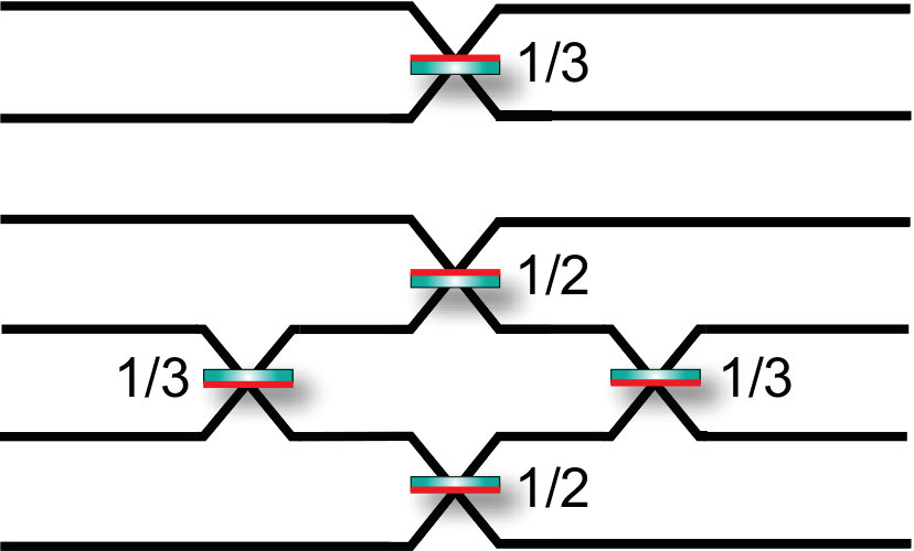 Figure 1
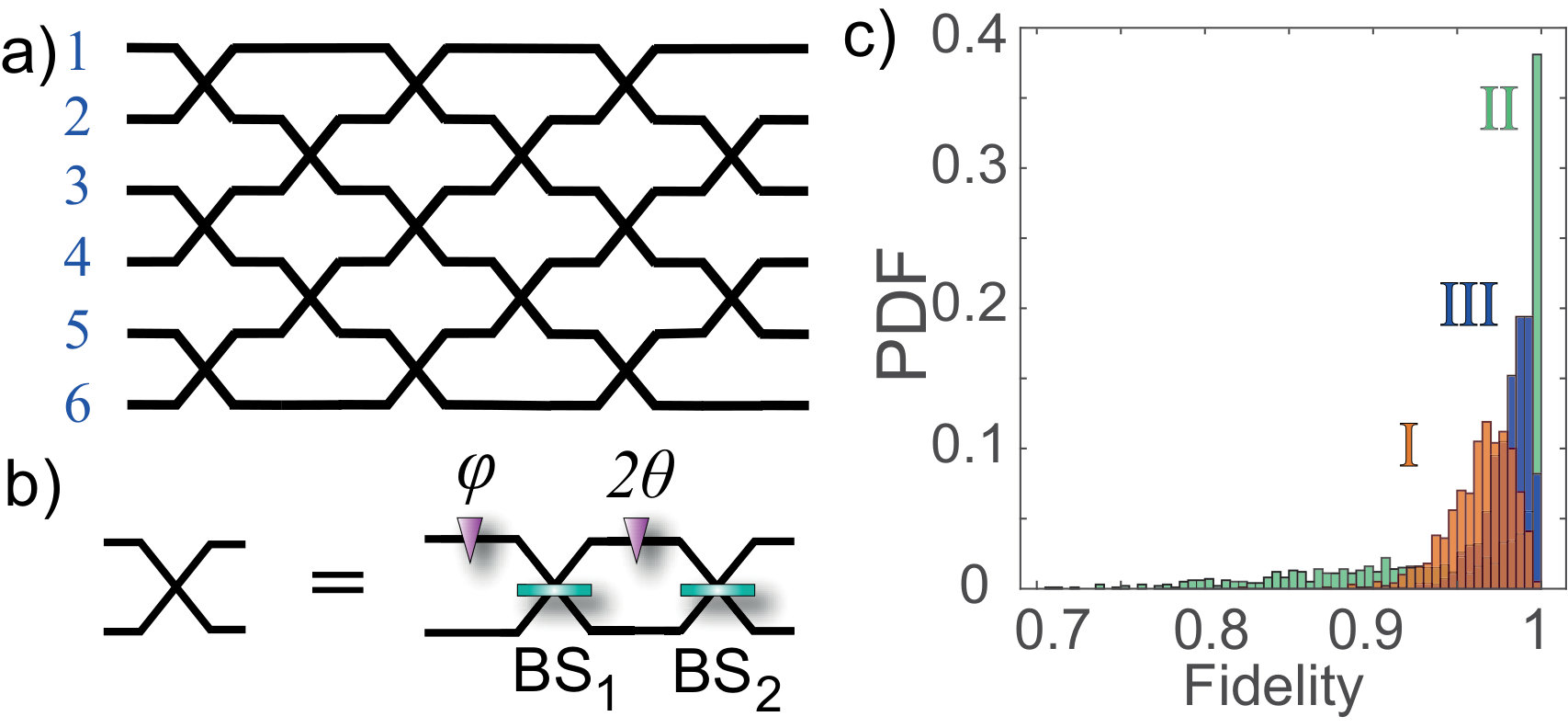 Figure 2
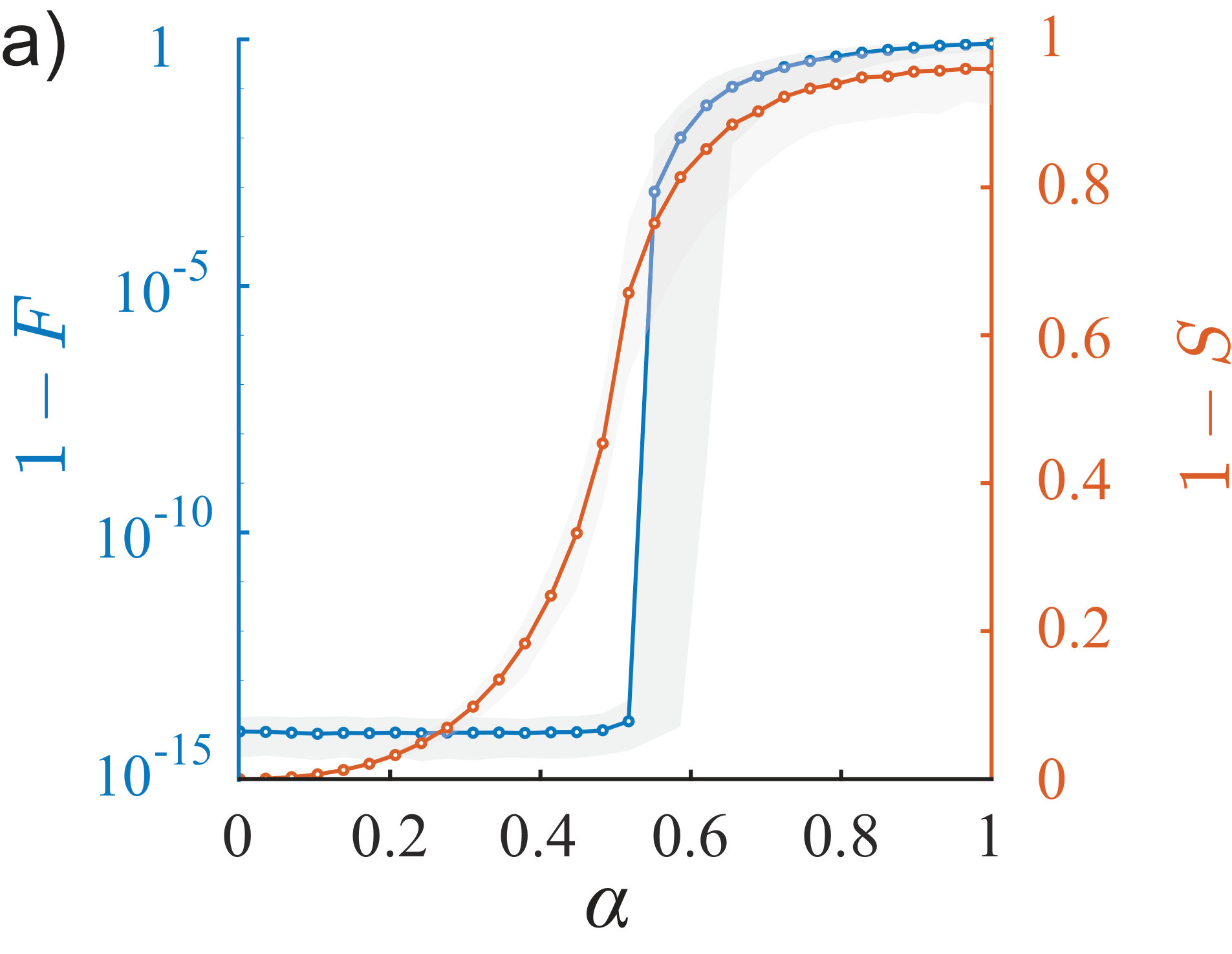 Figure 3
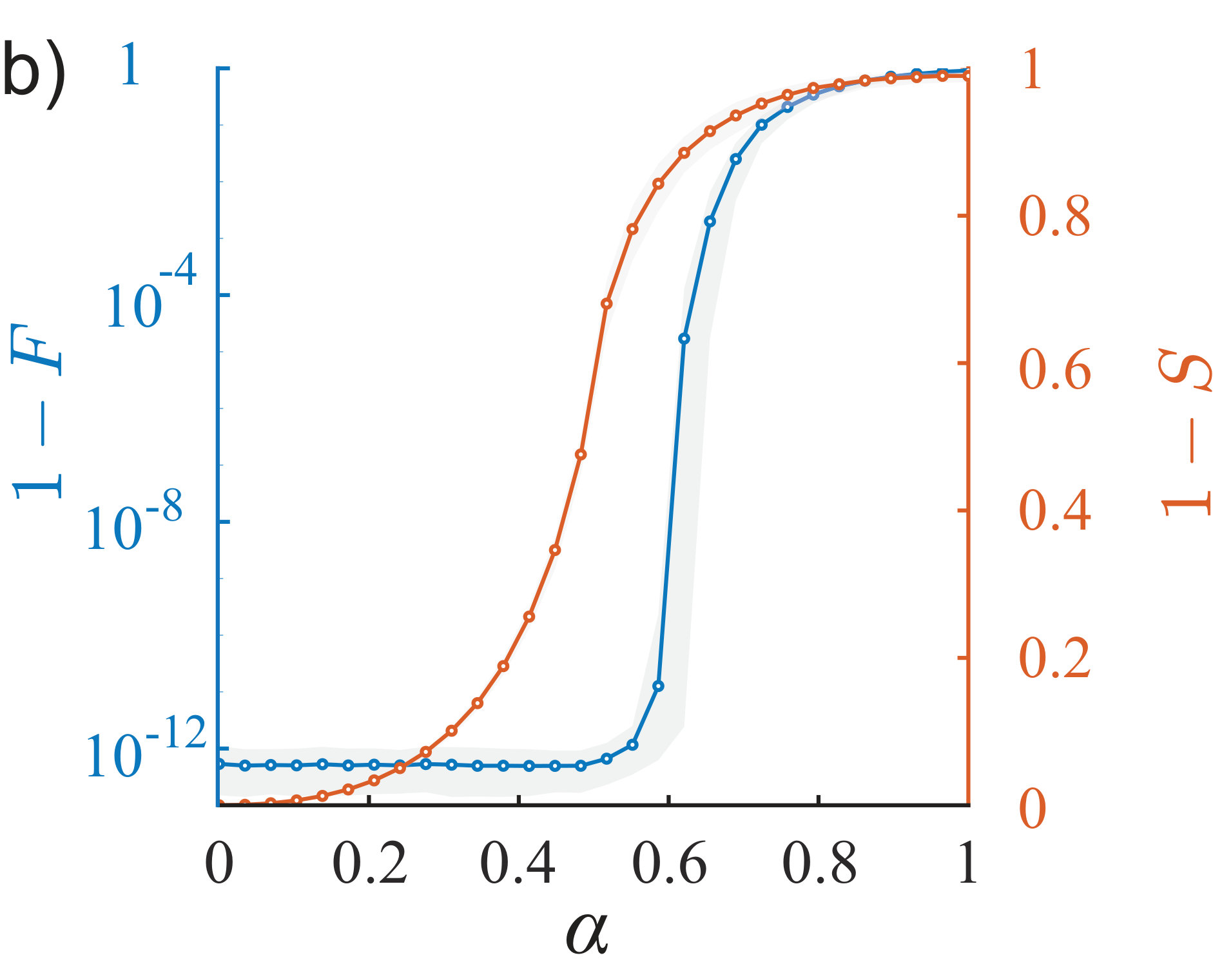 Figure 4
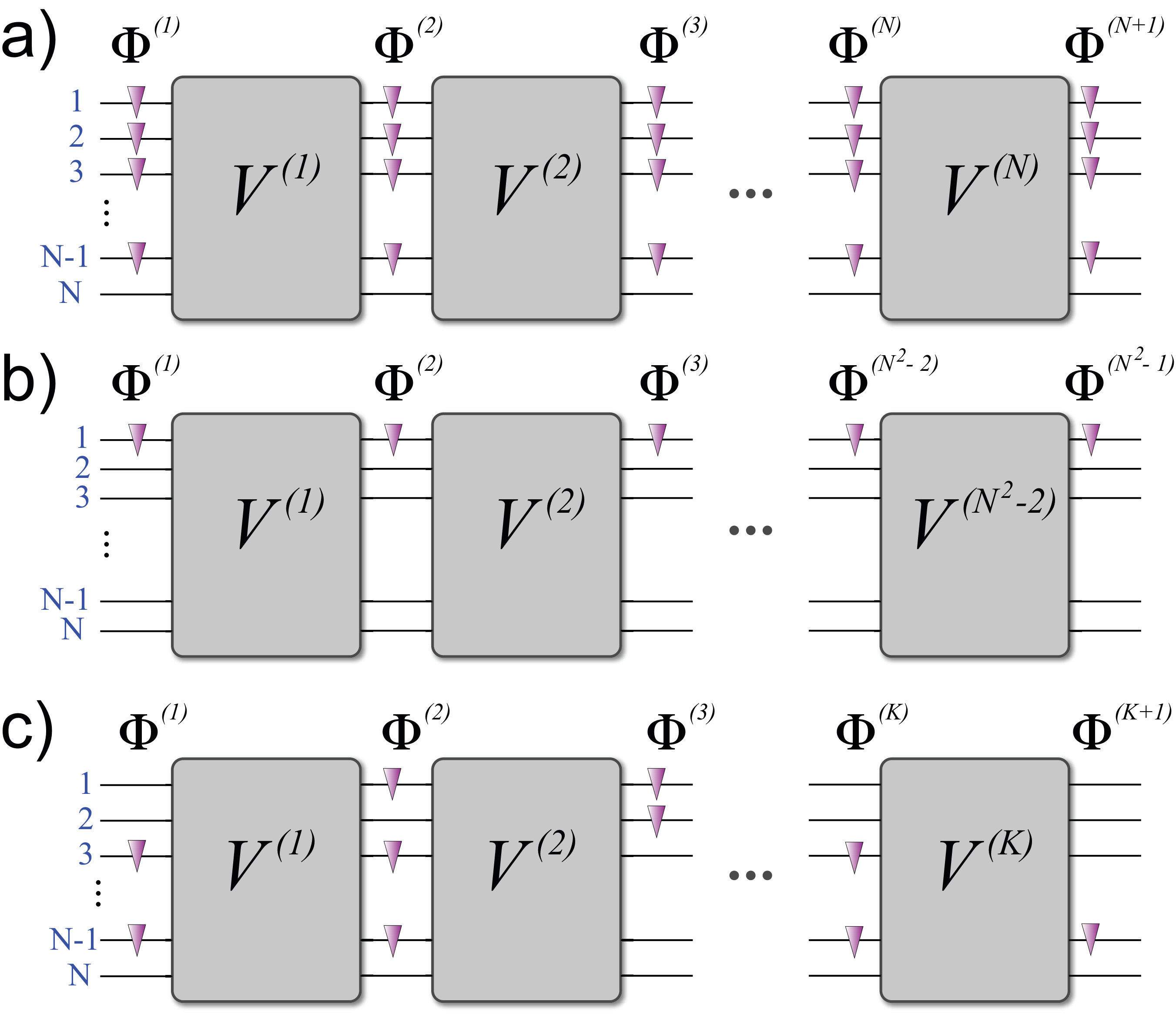 Figure 5
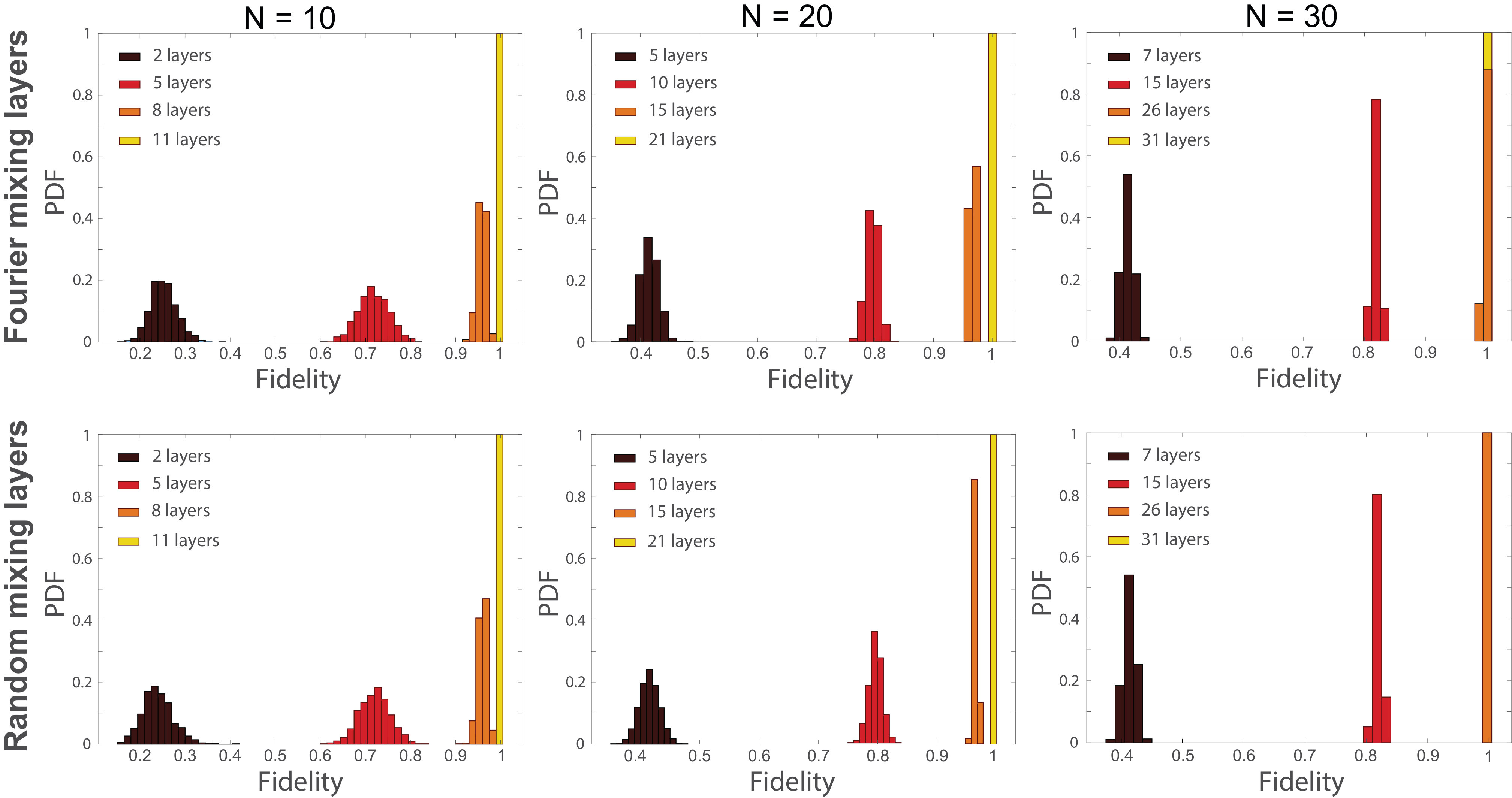 Figure 6
 Figure 7
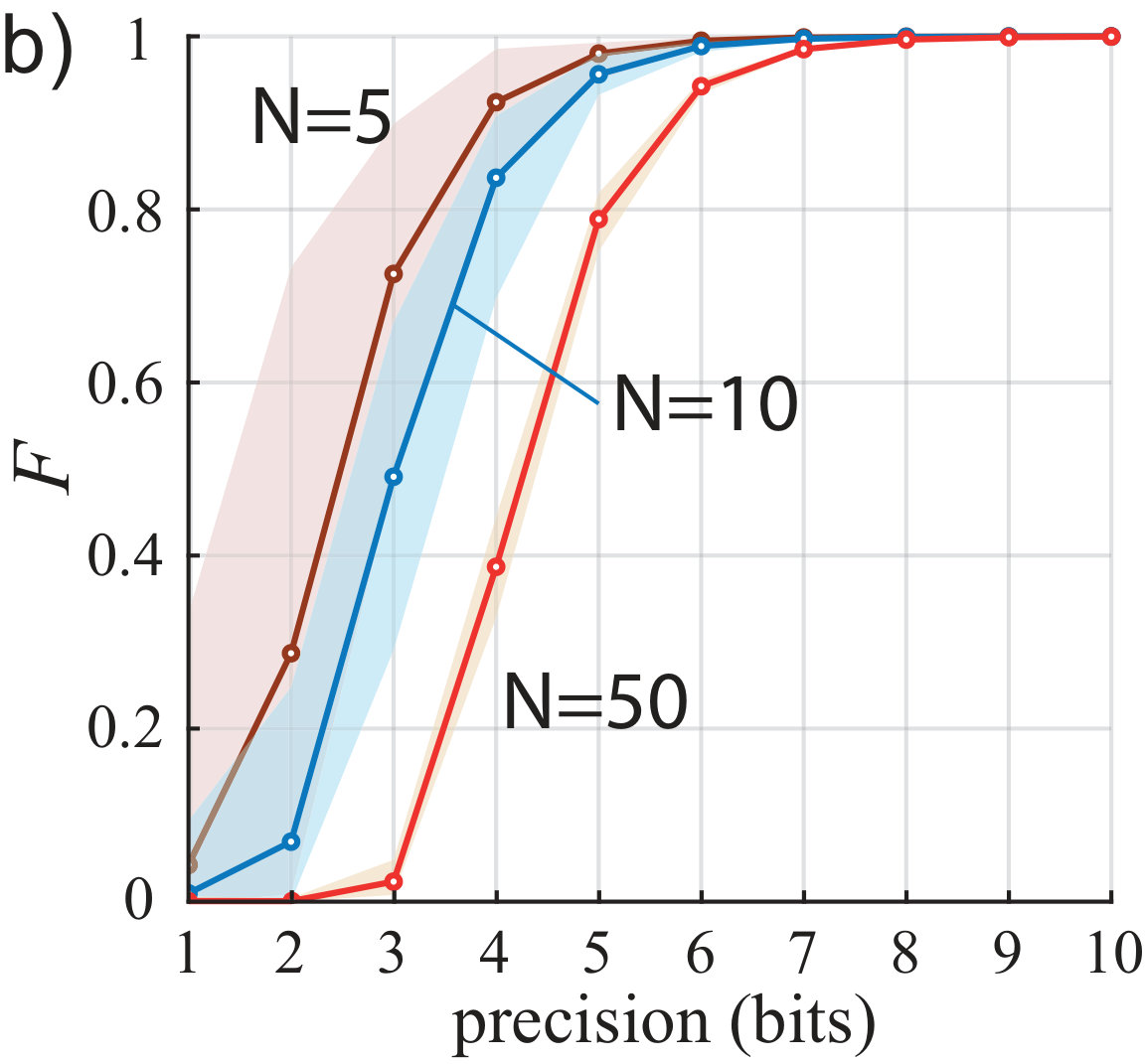 Figure 8
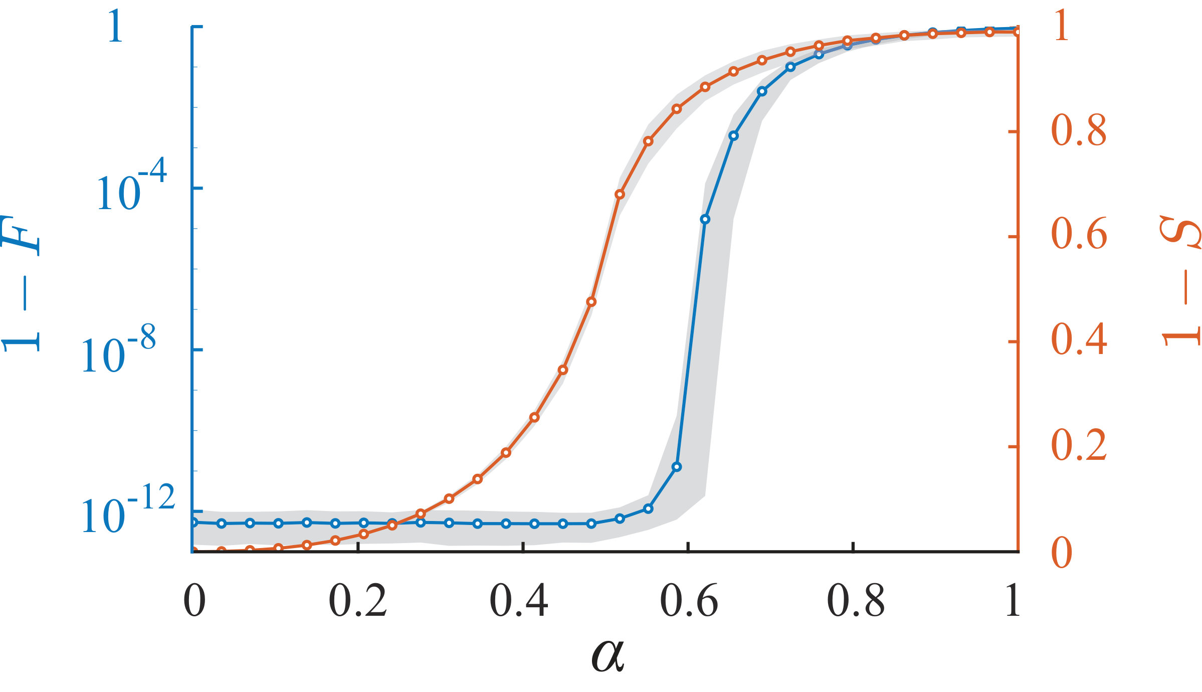 Figure 9
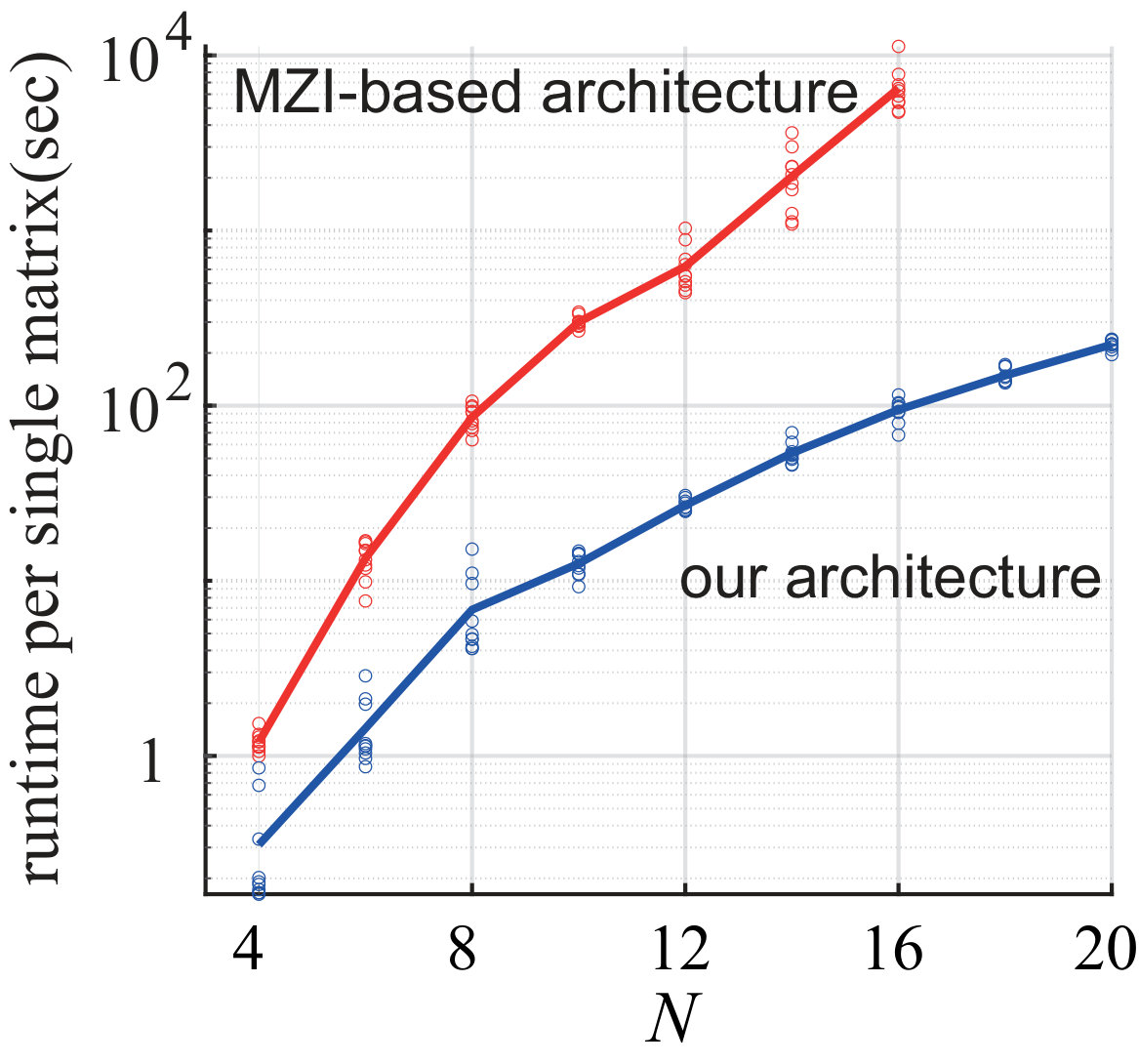 Figure 10
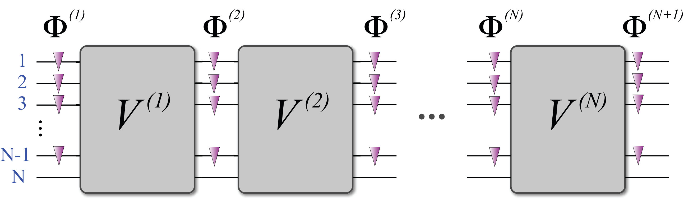 Figure 11
| 0.32616497+0.169709745i | -0.38944321+0.385222961i | -0.07487433+0.0140016576i | -0.56092302+0.144894222i | -0.09178299+0.182186722i | -0.37672097-0.199464971i |
| -0.59574492+0.341910943i | -0.06002442+0.0889329420i | 0.16555801+0.101417636i | -0.23277056+0.332764918i | 0.50921371-0.219642136i | 0.04267885-0.0685604080i |
| -0.11404973-0.0005635556i | 0.50625739-0.0702574186i | -0.28217237-0.692726708i | -0.22904901-0.008906423i | 0.0634065+0.0378401459i | -0.17627259-0.277850848i |
| 0.21269847+0.405463432i | -0.01962757+0.030734163i | 0.00386132-0.166814050i | 0.11549117-0.405381161i | 0.52450465+0.316155727i | -0.12388211+0.439441303i |
| -0.19696007+0.129259070i | -0.2829352+0.136684498i | -0.23585629-0.394794001i | -0.07037407+0.253348908i | -0.32129528+0.173338317i | 0.47736737+0.451640055i |
| 0.02205175-0.338176828i | -0.57000713+0.0471133316i | -0.12412351-0.377189984i | 0.43404681+0.108197637i | 0.33695188-0.153353789i | -0.13322881-0.213157689i |
| channel () | phase layer () | ||||||
|---|---|---|---|---|---|---|---|
| 1 | 2.51592377 | 3.52826283 | 0.87421821 | 3.24176442 | 2.92188993 | 1.24223769 | 4.30510568 |
| 2 | 0.96157148 | 2.57238693 | 4.75174626 | 2.81009478 | 3.53499635 | 3.46774956 | 6.21377173 |
| 3 | 5.5529059 | 3.32914678 | 1.0145169 | 6.25955126 | 1.27532946 | 0.43181492 | 0.91744755 |
| 4 | 1.61215433 | 2.30343223 | 3.12035203 | 4.50728974 | 1.78382232 | 4.68552694 | 2.70720777 |
| 5 | 1.50025594 | 2.0348859 | 1.36720772 | 4.31057832 | 1.88508855 | 2.81028466 | 0.20069949 |
Peer Reviews
No public reviews on file for this paper yet. If you reviewed it on a platform where reviews are public (OpenReview, ICLR, NeurIPS, ICML), you can paste yours below so the community can read it here.
Videos
No videos yet. Explain this paper in a talk, walkthrough, or lecture? Add one.
Robust architecture for programmable universal unitaries
M. Yu. Saygin
Quantum Technologies Center, Faculty of Physics, Lomonosov Moscow State University, Leninskie gory 1, building 35, 119991, Moscow, Russia
I. V. Kondratyev
Quantum Technologies Center, Faculty of Physics, Lomonosov Moscow State University, Leninskie gory 1, building 35, 119991, Moscow, Russia
I. V. Dyakonov
Quantum Technologies Center, Faculty of Physics, Lomonosov Moscow State University, Leninskie gory 1, building 35, 119991, Moscow, Russia
S. A. Mironov
Institute for Nuclear Research of the Russian Academy of Sciences, 60th October Anniversary Prospect, 7a, 117312 Moscow, Russia
Institute for Theoretical and Experimental Physics, Bolshaya Cheriomyshkinskaya, 25, 117218 Moscow, Russia
Moscow Institute of Physics and Technology, Institutski pereulok, 9, 141701, Dolgoprudny, Russia
S. S. Straupe
Quantum Technologies Center, Faculty of Physics, Lomonosov Moscow State University, Leninskie gory 1, building 35, 119991, Moscow, Russia
S. P. Kulik
Quantum Technologies Center, Faculty of Physics, Lomonosov Moscow State University, Leninskie gory 1, building 35, 119991, Moscow, Russia
Abstract
The decomposition of large unitary matrices into smaller ones is important, because it provides ways to realization of classical and quantum information processing schemes. Today, most of the methods use planar meshes of tunable two-channel blocks, however, the schemes turn out to be sensitive to fabrication errors. We study a novel decomposition method based on multi-channel blocks. We have shown that the scheme is universal even when the block‘s transfer matrices are chosen at random, making it virtually insensitive to errors. Moreover, the placement of the variable elements can be arbitrary, so that the scheme is not bound to specific topologies. Our method can be beneficial for large-scale implementations of unitary transformations by techniques, which are not of wide proliferation today or yet to be developed.
Linear transformations of multiple channels are ubiquitous in many applied fields, as well as in fundamental research. The implementations of linear multi-channel transformations are particularly important in the optical context, in which they are used as indispensable components of communication and computing systems, in particular, those based on novel approaches to information processing. For example, universal optical interferometers – devices capable of performing arbitrary linear transformations – are exploited as mode unscramblers Annoni et al. (2017) or as a part of photonic neural networks Shen et al. (2017); Hughes et al. (2018).
In addition to classical applications, universal optical interferometers play an important role in the implementations of quantum algorithms. In particular, multi-channel interferometers are a necessary part of the promising quantum computing platform that leverages linear-optical circuits and non-classical properties of photons to realize quantum algorithms Harris et al. (2018); Rudolph (2017). Recent works have demonstrated the versatility of linear-optical quantum systems and their ability to perform a number of quantum computing tasks ranging from the well-known algorithms Politi et al. (2009); Zhou et al. (2013) to the more specific ones, such as boson sampling Spring et al. (2012); Broome et al. (2012); Crespi et al. (2013) and variational algorithms Peruzzo et al. (2014); Wiebe and Granade (2016); Wang et al. (2017). The efficient realization of the later two classes of algorithms was made possible by the universal programmable interferometers Carolan et al. (2015).
The complexity of the multi-channel scheme, which is quantified by the number of channels in the interferometer and its programmability, defines its practical utility. These characteristics, however, are largely determined by a particular architecture used to construct the interferometer. Nowadays, the most widely used universal architectures belong to different planar varieties. One reason for this is the fact that planar schemes are easier to realize by the mature integrated photonics technology. On the other hand, methods have been devised that enable decomposition of large unitary matrices into planar meshes of smaller building blocks.
The decomposition methods of wide use today are obtained from the unitary matrix factorization theorem proposed in Hurwitz (1897), which was adopted to construct planar reconfigurable schemes, for example, in Reck et al. (1994); Clements et al. (2016). In the linear-optical context such a multi-channel scheme has a form of a mesh, constructed out of tunable Mach-Zehnder interferometers (MZIs), thereby enabling the whole interferometer to be reconfigured by tuning the variable phase elements Reck et al. (1994); Clements et al. (2016). For these schemes to be universal, the beam-splitters that constitute the MZIs should necessarily be balanced, therefore, imposing strict requirements on the fabrication tolerances. However, in practical implementations this condition is not fully satisfied, so that the multi-channel transformation is universal only to a certain degree Burgwal et al. (2017). This negative effect becomes more pronounced as the interferometer scheme is scaled up. Therefore, the realization of sophisticated information processing algorithms with optics calls for the development of novel architectures for multi-channel interferometers that are more resilient to the implementation errors.
In this work we explore an alternative approach to bulding large-scale univeral interferometers, which is drastically different from the known methods based on meshes of two-channel blocks. It is based on sequences of fixed multi-channel mixing blocks instead of arrays of balanced beam-splitters. As a result, the interferometric scheme provides the freedom to choose the transfer matrix of the blocks out of the continuous unitary space. Surprisingly, such schemes turn out to be extremely robust to perturbations in the transfer matrices of the blocks, in fact, as we show below, they may be chosen at random, and the desired transformation may be dialed later on the manufactured device by tuning the phaseshifts only. In addition, the placement of the variable phase shifts in the scheme can also be chosen arbitrary. Since no relation to the scheme topology is implied in the analysis, a wide variety of technologies can be used to realize it in practice, for example, those based on frequency and temporal encoding, that may potentially enlarge the scale of the universal interferometric schemes.
Methods of decomposition of unitary matrices. — Several types of parametrization for unitary matrices are known Hurwitz (1897); Jarlskog (2005); Dita (1982); Ivanov and Vitanov (2008), however, only few of them give a recipe to build up large devices out of elementary blocks that a convenient to realize in practice. Linear optics is the most representative domain of practical application for multi-channel transformations, where their implementations are employed to transform the input vector of field amplitudes into the output vector by transformation, described by a matrix : . Following the decomposition methods, the required matrix , that can be regarded as a transformation, is obtained by setting appropriate values of some parameters, characterizing the elements in the actual physical network Reck et al. (1994); Clements et al. (2016).
A natural building block for multi-channel schemes in the context of optics is a MZI consisting of a pair of static balanced beam-splitters and two variable phase shifters. Adding a third phase to the MZI allows to cover an entire group Tilma and Sudarshan (2002) with the transformation matrix:
[TABLE]
where and are the Pauli matrices, , and are the phase parameters.
Although, in principle any fixed beamsplitter transformation mixing a pair of optical modes densely generates Bouland and Aaronson (2014), a more efficient way is to implement a network scheme allowing to program the required unitary using tunable MZIs. The experiments reported in Carolan et al. (2015); Harris et al. (2017, 2018); Dyakonov et al. (2018) have demonstrated the capabilities of such a network design to experimentally approximate arbitrary unitaries. However, the performance of the linear optical network heavily depends on the quality of individual MZI elements. For example, the work Burgwal et al. (2017) studied the effect of individual beam-splitter errors on the overall fidelity and concluded that the beam-splitter reflectivity errors of few percents diminish the quality of the unitary transformations significantly. This makes a subset of unitary transformations unavailable for the programmable linear optical network composed of imperfect optical elements Russell et al. (2017).
As an illustrative example, consider the decomposition proposed in Clements et al. (2016), which is widely used today to construct reconfigurable planar optical schemes. The corresponding scheme layout is illustrated in Fig. 1a for a number of inputs and outputs . Its main building block – an MZI is depicted in Fig.1b. Fig. 1c illustrates the negative effect of the beam-splitter imbalances on the quality of the transformation, clearly witnessing the sensitivity of this decomposition to errors.
Layered decompositions with static multi-channel blocks. — The decomposition we study in this work is based on static multi-channel blocks, rather than two-channel balanced beam-splitters. The schematic of the decomposition is shown in Fig. 2. It is built up of multiple layers, that come in two types, which are stacked alternately. The variable layer consists of independent single phase shifts , so that its -channel transfer matrix has the diagonal form: where is a vector of phase shifts, thus, we call it the phase layer. The other type of layer, in the following referred to as the mixing layer, introduces interaction between the channels that is required for multi-channel interference. It is the aim of our work to find out what transfer matrices should these mixing layers have in order for the whole scheme to be universal. Moreover, we are interested in a general case, when the mixing layers can have different transfer matrices , so that the overall transformation has the following form:
[TABLE]
where with being the set of phases describing the layer with index , is the number of mixing layers. The decomposition (2) enables a variety of schemes, each having different number of layers at a given . Here, we describe the case of 111See Supplemental Material [url] for other possible variants of the interferometer schemes.
Previous works considered special cases of decomposition (2) with specific choice of . A design of the form (2) with the mixing layers described by the discrete Fourier transform matrix:
[TABLE]
, implemented in a planar integrated photonic circuit was studied in Tang et al. (2017). Work Zhou et al. (2018) deals with the mixing layers implemented by regions of coupled waveguides. The authors of these works provided some numerical evidence in favor of universality of this specific types of circuits. In both these works, the transfer matrices of the mixing layers were essentially defined with a specific system in mind. Besides, the number of phase shifts per layer was , which is a maximum possible number. Relevant ideas concerning decomposition (2) can be found in Lu et al. (2018, 2019); Tang et al. (2017). In this work we show that the class of transfer matrices suitable for universal programmable schemes is not bounded to some specific instances, to the contrary, it occupies a large part of the group volume.
We first notice that by simple counting of independent parameters necessary to define an arbitrary unitary matrix, a universal scheme performing an SU() transformation should have at least tunable phase shifts. We will restrict our attention to the schemes using exactly this minimal set of phases.
We quantify performance of the decomposition (2) by fidelity, defined as:
[TABLE]
which compares a target unitary matrix and an actual transfer matrix realized by the decomposition (2). Provided that the matrices and are equal up to a global phase, fidelity (4) gets its maximum value .
In contrast to the known decomposition of Clements et al. (2016), which comes with an analytical procedure allowing to obtain a set of phases at which for any given , we could not find an analytical solution for the general decomposition (2). Therefore, a numerical optimization procedure has been used. Our numerical algorithm is based on the basinhopping algorithm realized using the SciPy python library. Given a unitary matrix , the algorithm was searching for a global minimum of infidelity over the space of phase vectors (). To decrease the chance of sticking into local minima, we used multiple runs of the basinhopping routine with random initial values of the phases. The algorithm has reasonable efficiency and has sub-exponential runtime dependence on the interferometer size 222 See Supplemental Material [url] for the analysis of the efficiency of the numerical algorithm runtime and the effect of finite phase shift precision on transformation quality, which includes Refs Pai et al. (2019).. This way, we have achieved the error of calculating the global minimum on the level of 333The code is available on request. Each numerical experiment involved optimization over a series of matrices drawn from the Haar random distribution using the method based on the QR-decomposition of random matrices from the Ginibre ensemble Mezzadri (2006).
Let us now discuss the choice of the transfer matrices of the mixing layers, used in construction of multi-channel transformations. Surprisingly, not only specific fixed unitaries are suitable, but almost any unitary matrix will work as a mixing layer. Moreover, the mixing transformation need not be fixed, it can vary from layer to layer. To demonstrate that, we chose every matrix in (2) at random using the very same approach, described above for generation of . Fig. 3 presents the results of optimization for decomposition depicted in Fig. 2a for the case of a fixed transfer matrix, namely a DFT matrix (3), and random transfer matrices of the mixing layers. In the optimization process we varied the number of phase layers, ranging from small values containing less phase shifts than required for universality, which is done for illustrative purposes, to the proper number containing in total phase shifts. The worst value of infidelity corresponding to the latter case for all matrix sizes presented was not greater than and its non-vanishing value is attributed to the finite accuracy of the implementation of the numerical algorithm.
To make sure, that our result is not a mere artifact of high-dimensional random matrix generation, we have considered a specific example of an SU(6) transformation corresponding to a probabilistic linear optical CNOT gate Ralph et al. (2002). We were able to reproduce this particular unitary with infidelity of using random mixing layers 444 See Supplemental Material [url] for a particular example of linear-optical CNOT gate and robustness analysis of the interferometer architecture under consideration..
To demonstrate that our architecture is resilient to practical constraints and errors that can undermine the universality of the interferometer, we have added random perturbations to the mode mixing layers according to the following procedure. First, we construct the parametrised matrix
[TABLE]
which is a weighted sum of an initial matrix , and a Haar-random perturbation , modeling imperfections. Since is non-unitary at , we then apply the singular value decomposition: , where and are unitary matrices and is a diagonal matrix. The unitary part of (9) as: . Even for a rather high value of we have observed essentially no effect of the perturbation on the infidelity with an ideal CNOT matrix.
There are obvious examples of matrices which are not suitable for mixing layers, such as an identity matrix or permutation matrices. However, as our numerical results suggest, the relative volume of these matrices is negligible for large . Parametrized families of matrices allow us to analyze the worst case performance of our scheme. Changing in (9) with we can see how close to a worst case we can get before the scheme becomes non-universal. For each value of a series of target matrices and block transfer matrices were generated at random from a Haar-uniform distribution and fidelity (4) was maximized over the space of phase shifts. Fig. 4 demonstrates the infidelity of total transformation as a function of parameter along with the infidelity for blocks , where is fidelity between the initial and the perturbed block transfer matrices. As can be seen from the figure, while for each block grows monotonically, the dependence of infidelity for the whole transformation has a clear threshold behaviour, namely, it stays on the constant level of accuracy of the numerical algorithm as far as does not exceed value after which it grows abruptly. We did not study the dependence of the threshold value of on the interferometer size in details, but results for and suggest, that it may slightly increase with increasing 555 See Supplemental Material [url] for the performance analysis of the interferometer architecture under consideration..
Theoretical framework. — The strict proof of the universality implies showing that the transformations should form a group under matrix multiplication and then prove that this group densely covers the group of the corresponding dimension. We could not find the rigorous proof neither for the simplest nontrivial case of nor for the general case of arbitrary dimension. However, we have worked out preliminary considerations on the structure of the manifold described by (2) 666 See Supplemental Material [url] for the analytical results, which includes Refs. Melnikov et al. (2018); Kowalevicz et al. (2005); Yariv (1973); Spagnolo et al. (2012).
Conclusion. — Our work demonstrates that multi-channel layered schemes provide an alternative architecture for universal linear-optical unitaries. This architecture is not limited to specific strictly predefined transfer matrices, such as, for example, a discrete Fourier transform as in previous proposals Huhtanen (2007); Lu et al. (2018). Namely, we have shown that the transfer matrices of the static blocks can be chosen from a continuous class of unitary matrices at random without sacrificing the quality of approximation for an arbitrary target unitary. This also comes immediately with resilience to errors that usually occur in implementations. In practice, the interferometer manufactured with imperfect mixing layers may be tuned to implement the desired transformation post-factum by tuning the phase-shifts only and optimizing the measured fidelity with the desired transformation Dyakonov et al. (2018). Therefore, these results, showing that one does not necessarily need to carefully engineer the building blocks of the schemes to be able to reach almost any matrix in the unitary space, are of primary importance for experimental applications.
Acknowledgements. This work was supported in part by RFBR grants # 19-32-80020/19, 18-51-05015 and by the Foundation for the Advancement of Theoretical Physics and Mathematics (BASIS). Authors are grateful to I.Bobrov, A.Mironov, A.Morozov, An.Morozov, M.Olshanetsky and Y.Zenkevich for fruitful discussions.
Supplemental material
Appendix A Different variants of the universal interferometer schemes
The general form of the layered decomposition
[TABLE]
may be realized in various schemes, each having different depths at a given , as quantified by the number of mixing layers . We categorize the schemes into three varieties, which are depicted in Fig. 5.
The one shown in Fig. 5a uses a maximum possible number of phase shifts per layer equal to , yielding the lowest possible depth . The opposite case is illustrated in Fig. 5b, where the phase layers include only single phase shifts, thus, the total depth is maximal. Finally, yet another scheme variety, depicted in Fig. 5c, permits a number of configurations, in which the number of phases in the phase layers can be arbitrary and can differ from layer to layer. Therefore, in this case, the depth can take values in the range from to .
Appendix B Example of a linear-optical CNOT gate
As a specific example of a multi-channel transformation, we consider a -channel interferometer scheme depicted in Fig. 6, which is exploited in linear-optical quantum computing as an implementation of a CNOT logical gate Ralph et al. (2002) for dual-rail encoded qubits. Fig. 6 illustrates its canonical representation in the form of a cascaded scheme constructed from standard two-mode beam-splitters. The transfer matrix of the interferometer has the following form:
[TABLE]
To demonstrate that the interferometers of our architecture is capable of implementing the transfer matrix (7), we selected a single -channel transfer matrix for all the mixing layers by generating a unitary matrix at random from a Haar-uniform distribution. The elements of this transfer matrix are listed in Table 1. Then, we found the values of variable phase shifts that reconfigure our interferometer to approximate the transfer matrix (7) of the CNOT gate as closely as possible. The corresponding phase shifts found in the optimization procedure are listed in Table 2. The achieved residual error of the numerical optimization is quantified by the infidelity value, , and in this case amounts to . Since the infidelity is very small, we conclude that the matrix (7) is reproduced within the numerical precision.
Appendix C Robustness of the interferometer architecture
Our numerical results suggest that a wide range of unitary matrices, which occupy the major part of the unitary group, can be used as block transfer matrices for universal interferometers of our architecture. Here, we demonstrate that our architecture is resilient to fabrication errors and constraints, imposed by the technology at hand.
A model of perturbation which should be used for the block matrices is crucially dependent on a the specifics of the manufacturing facility at hand. As a proof-of-principle, here we model the perturbations by the following procedure. We take the unperturbed matrix for the mixing layer to be the matrix , which is enlisted in Table 1. Secondly, we generate a perturbation matrix , which is a Haar-random unitary obtained similarly to . Then, a new parametrized matrix is constructed: , with quantifying the perturbation strength. However, the mixture of two unitary matrices is not unitary, therefore, we then use a singular value decomposition:
[TABLE]
by means of which the parametrized unitary can be derived as: . In the limiting cases: . We constructed the 6-channel interferometer scheme of our architecture with 6 different blocks, where the first one is and the other five having transfer matrices generated independently by the aforementioned procedure with parameter . By using the numerical optimization algorithm to calculate phase shifts that implement the matrix , we arrive at infidelity values – the typical error of the optimization algorithm.
Appendix D Worst-case performance analysis
Not all transfer matrices may be used for the mixing block. Indeed, at least a unity matrix and permutations as mixing layers obviously will not allow for good approximation quality. At the same time in our numerical experiments we generated mixing matrices at random and have never encountered a case where the optimization procedure failed to converge. It is therefore interesting to understand, how close to the worst-case layer should one get to have noticeble reduction in the approximation fidelity. Parametrized families of matrices allow us to analyze the worst-case performance of our scheme.
In our model for worst-case performance, the block transfer matrices have been constructed, that depend on the parameter taking values from [math] to . The value of describes an error-free unconstrained scenario when are known to be suitable for the universal interferometer, while corresponds to the opposite case, when the block transfer matrices are definitely of no use for the interferometer. Namely, we generated unitary matrices at random from a Haar-uniform matrix distribution and independently for each layer, following the procedure from the main text of the paper. Then, these matrices are ”corrupted” by the -weighted sum:
[TABLE]
where is a matrix that is known to represent the worst case for static multi-channel block. There exist a number of matrices that are obviously unsuitable for universal inteferometer, such as diagonal and block-diagonal matrices, which do not provide necessary inter-channel mixing. We chose to be an identity matrix , that can be regarded as one of the worst choices for the block transfer matrix (on par with all the diagonal matrices). Since the sum (9) is generally not unitary, the singular value decomposition was used:
[TABLE]
with which the -parametrized unitary is derived as
[TABLE]
Obviously, and , so by continuously varying the parameter one can tune between the good choice of the block transfer matrix with which the interferometer is universal and the worst choice, respectively.
To quantify the similarity between the transfer matrices for a single block we use the fidelity measure averaged over block transfer matrices:
[TABLE]
In order to investigate how the degree of admixture of the ”bad” matrices (quantified by ) influences the transformation quality, we have performed the numerical analysis. For this purpose, we studied the distribution of fidelities obtained for a set of randomly generated target unitary matrices , which were to be implemented by the interferometer, for each value of . Each random matrix was accompanied by a new set of block transfer matrices , also generated at random. Fig. 7 shows the obtained results where the dependencies of the transformation infidelity and infidelity between the mixing blocks (averaged over the all blocks in the scheme) are plotted. As can be seen from the figure, while infidelity between the block transfer matrices grows monotonically with respect to , the transformation infidelity exhibits a threshold behavior with the small constant value for defined by the accuracy of the numerical algorithm used. The threshold where fidelity starts increasing is observed for quite large values of , suggesting additional error resilience of our interferometer architecture.
Appendix E Computational resources of the numerical optimization
Finding the values of tunable phase shifts that make the programmable interferometer to implement the target transformation can demand significant computational resources, especially when optimization is performed on-line with a real interferometer device. There are numerical methods and software packages currently available that enable effective optimization of multichannel interferometers of previously known architectures (see, e.g. Pai et al. (2019)). Here, to demonstrate that our architecture does not require extraordinary computational power for re-programming, we used the basin-hopping optimization algorithm, which is a part of the SciPy package.
We performed numerical optimization for interferometers of different size and tracked the time it took to obtain high fidelity values satisfying the threshold condition . It should be noted that for the major part of the instances the resultant infidelity was far better than the threshold value. Both interferometers of our architecture and the MZI-based architecture by Clements et al. Clements et al. (2016) were modelled using the same CPU, thereby providing the possibility to compare the computational costs. Fig. 8 shows the dependence of the runtime as a function of the interferometer size . As can be seen from the figure, the scaling of the optimization runtime with is much better for the interferometers of our architecture than for the MZI-based counterpart. Notice, however, that a specific interferometer architecture generally requires a specific optimization algorithm, which is optimal for this architecture and can be sub-optimal for another. Devising a specialized optimization algorithm for our architecture is beyond the scope of our work.
Appendix F The effect of finite phase shift accuracy on the transformation quality
In practice, one can not set the values of the tunable phase shifts with arbitrary precision. To study the negative effect related to phase imprecision on the transformation quality, we have performed numerical analysis and have shown that even moderate precision allows for achieving very-high-fidelity transformations in the interferometers of our architecture. We quantified the phase accuracy by the number of bits that is guaranteed by the actual phase shifter elements. Thus, the values of the phase shifts are written as , where describes the th phase in the ideal case, is the deviation induced by the phase shifter (). Obviously, in terms of bits, the phase shift is said to provide the -bit precision if .
Without loss of generality, we consider the specific transfer matrices of the static blocks to be the discrete Fourier transform matrix, i.e. for all . We also consider the performance of the widely-used architecture by Clements et al. Clements et al. (2016) for comparison. For a given , we obtained the transfer matrix which needs to be implemented by the interferometer by generation of at random from a uniform distribution. Then, the deviations were added to and a new transfer matrix was calculated accordingly.
To have a specific model of inaccuracies , the errors were independently drawn from the uniform distribution in the range from to . For each target matrix at each a series of matrices were generated this way. Fig. 9 shows the dependence of transformation fidelity as a function of precision bits . As can be seen from the figure, the interferometers of our architectures do not have special requirement on the phase shifts precision, as they are as tolerant as the known counterpart by Clements et al. Clements et al. (2016); bits precision is enough to approximate an -channel unitary matrix with high fidelity for , which is not a problem with the current technologies.
Appendix G The decomposition structure of SU(3) transformation
Let us now develop a theoretical framework describing the capabilities of the unitary decomposition. Firstly we note that if arbitrarily long sequences of fixed transformations are allowed, a set of only two different matrices is enough to generate any transformation Melnikov et al. (2018). The proof is straightforward: the first matrix is an irrational phase shift, its powers densely cover all phase shift matrices, and the second matrix is the mixing unitary (4). The question of constructing an arbitrary unitary with a sequence of and phase shifts of a fixed length is an open question. Here we provide strong evidence in support of the claim, that it is possible to achieve this goal with the sequence (3).
We have worked out preliminary considerations on the structure of the manifold described by (3). The tangent space of transformation manifold at is 8-dimensional, which means that in principle the transformation is flexible enough to reconstruct the algebra. However, there exist zero-measured submanifolds on which some of the phase factors from the set are linearly dependent in the first order. This means that the coordinates are singular on some submanifolds analogous to the pole in polar or spherical coordinates. Identity of the group lies in the singular submanifold. We show explicitly, that it indeed is a coordinate singularity and the group manifold in the vicinity of the unity matrix is smooth. We do not claim the rigorous proof of universality, but we hope that our considerations may give a deeper insight into the problem.
We study a particular example of tritters (quantum fourier transform matrices) representation of an group, i.e. general 3 by 3 unitary matrices with (in what follows matrices ). The representation is as follows
[TABLE]
or one can add an additional tritter matrix
[TABLE]
where
[TABLE]
with parameters , and
[TABLE]
A general element of the group can be represented as an exponent of an algebra generator, in particular, a unitary matrix (fundamental representation) is an exponent of an anti-Hermitian matrix. In the case of phase rotating gates a unitary matrix is an exponent of diagonal Gellmann matrices
[TABLE]
where Gellmann matrices form the basis in the algebra. Below we use the following notations for Gellmann matrices:
[TABLE]
[TABLE]
[TABLE]
[TABLE]
Diagonal matrices can be permutated with tritter gates due to the following conjugation property
[TABLE]
[TABLE]
Since , formulae (20) and (21) enables one to express as follows
[TABLE]
where we have linearly reparametrized for the sake of brevity.
Let us now use the identity which follows from Baker-Campbell-Hausdorff (BCH) formula for the two middle terms in (22)
[TABLE]
One calculates
[TABLE]
The next step is to merge the two first exponents in (24) by making use of the original BCH formula. The functional independence of coefficients in front of in the resulting exponent would conclude the proof of universality. Unfortunately, this calculation appears too involved, and we were not able to sum the full BCH series.
There is, though, another way to deal with the tritter construction. It simplifies the local (algebraic) study, but still does not allow to prove universality on a group level. Let us notice that tritter is a matrix exponent of the following combination:
[TABLE]
and it can be conjugated with the phase gate:
[TABLE]
This allows one to perform the following procedure:
[TABLE]
where depends only on and , depends on the sums and and so on, hence, all four factors , , and are independent. Now we shift to separate the parameters and simplify the expression:
[TABLE]
so that each factor depends on it’s own couple of ’s. For the sake of brevity we also change the parameters in as follows,
[TABLE]
so that reads:
[TABLE]
In these notations SU(3) element reads
[TABLE]
This form of matrix may simplify its series decomposition in terms of .
Appendix H Vicinity of a point: an algebraic approach
Let us prove that the tangent space to our group manifold in a general point is 8-dimensional. The tangent space is provided by an equivalency class of a first order expansion of a group element. The corresponding tangent space to identity of a group is a conventional Lie algebra:
[TABLE]
For a general group element the tangent algebra is twisted by the inverse element:
[TABLE]
In other words, element of the algebra is
[TABLE]
su(3) commutation relations together with group structure would prove that it is indeed SU(3) group. At least, its universal envelope is SU(3), but finite factor is easy to exclude. Now we make a first order expansion (for instance using 28):
[TABLE]
The last two terms are obviously linearly independent combinations of and . Linear independence of combinations in was explicitly checked. We do not present the cumbersome answers, since the calculations are totally straightforward. This shows that the tangent space is indeed 8-dimensional.
This result holds in the general point of a group manifold. Unfortunately, there are zero-measured submanifolds where are linearly dependent. Indeed, one can expect that, for instance, if and phases in the gate are zeros, only two out of four parameters in the and gates survive. On the other hand, this does not necessarily make the dimension of the tangent space lower. In full analogy with the pole in polar or spherical coordinates these zero-measured submanifolds may indicate a coordinate singularity. The easiest way to check that the dimension of tangent space did not get lower in the vicinity of degenerate points is to solve numerically the equations of the form
[TABLE]
for small with an accuracy. The existence of the solutions for all indicate that the point is regular. The explicit numerical check has been performed around the unity matrix .
However, there is an analytic way to prove that the manifold is regular at a given point . First of all, we construct the metric of the manifold, in case of the Lie group – the Killing metric, which reads
[TABLE]
where stands for trace. The metric is by real symmetric matrix. It is degenerate in the points of (coordinate) singularities. But to check whether the manifold itself is singular or not, one has to find Riemann tensor: its regularity would mean regularity of the manifold. This is straightforward differential geometry computation, but very cumbersome. Thus, to simplify the calculation one can use series expansion around point (one has to keep enough terms of the series due to the second derivatives in expression for curvature and Riemann tensors). We found analytically the Riemann tensor of the manifold in the point corresponding to identity of the group. The tensor is regular, in particular, it is zero, so the manifold is not only regular, but also flat near this point.
Appendix I Multiport beamsplitter structure
A possible way of physical realization of the proposed structure (3) in linear optics in the case of is to use three-port beamsplitters, so called tritters, as the mode mixing elements , and phase shifters . A tritter is a three-port beamsplitter, which enables three input modes to simultaneously interfere in the three-arm directional coupler, formed by three evanescently coupled waveguides. Experimentally this device can be manufactured, for example, via the femtosecond laser writing technique in a transparent dielectric media Kowalevicz et al. (2005). The tritter is called balanced when a single photon entering one of three input ports has equal probabilities to exit from each of three output ports. The action of a balanced tritter on can be described by a unitary operator, mapping the input field creation operators to the output operators : , where is the matrix of a symmetric balanced tritter.
The matrix of a symmetric balanced tritter can be obtained as follows: let us consider propagation of three photons along the -axis in three equally coupled waveguides. Let be a photon creation operator in a -th waveguide (). According to the coupled mode theory the evolution of the photon creation operator during propagation along the -axis in three equally coupled waveguides could be described by the system Yariv (1973):
[TABLE]
where is the propagation constant, – the coupling coefficient between the neighbouring waveguides ( if is the same for all pairs of waveguides the tritter is symmetrical.)
The system (35) can be explicitly solved:
[TABLE]
where
[TABLE]
[TABLE]
It can be shown that the interaction length should be chosen as for a balanced tritter. Then the matrix of a symmetrical balanced tritter is (up to a phase shifts inserted in the input or in the output modes):
[TABLE]
which appears to be exactly the Fourier transform matrix (4) in case . Here, the subscript index marks the matrix size.
Similarly, it is possible to construct a symmetrical balanced four-path beamsplitter – a quarter. Such devices may also be implemented with the aid of femtosecond laser writing techninque Spagnolo et al. (2012). The quarter matrix is obtained in the same way as that for a tritter, and it is essentially the Fourier transform matrix:
[TABLE]
Using interference schemes (3) based on these particular multipath beam splitters and phase shifters one may implement an arbitrary unitary transformation in the corresponding dimension.
The reference list from the paper itself. Each links out to its DOI / PubMed record.
- 1Annoni et al. (2017) A. Annoni, E. Guglielmi, M. Carminati, G. Ferrari, M. Sampietro, D. A. Miller, A. Melloni, and F. Morichetti, Light: Science &Amp; Applications 6 , e 17110 EP (2017) , original Article. · doi ↗
- 2Shen et al. (2017) Y. Shen, N. C. Harris, S. Skirlo, M. Prabhu, T. Baehr-Jones, M. Hochberg, X. Sun, S. Zhao, H. Larochelle, D. Englund, and M. Soljacic, Nature Photonics 11 , 441 EP (2017) , article. · doi ↗
- 3Hughes et al. (2018) T. W. Hughes, M. Minkov, Y. Shi, and S. Fan, Optica 5 , 864 (2018) . · doi ↗
- 4Harris et al. (2018) N. C. Harris, J. Carolan, D. Bunandar, M. Prabhu, M. Hochberg, T. Baehr-Jones, M. L. Fanto, A. M. Smith, C. C. Tison, P. M. Alsing, and D. Englund, Optica 5 , 1623 (2018) . · doi ↗
- 5Rudolph (2017) T. Rudolph, APL Photonics 2 , 030901 (2017) . · doi ↗
- 6Politi et al. (2009) A. Politi, J. C. F. Matthews, and J. L. O’Brien, Science 325 , 1221 (2009) . · doi ↗
- 7Zhou et al. (2013) X.-Q. Zhou, P. Kalasuwan, T. C. Ralph, and J. L. O’Brien, Nature Photonics 7 , 223 (2013) . · doi ↗
- 8Spring et al. (2012) J. B. Spring, B. J. Metcalf, P. C. Humphreys, W. S. Kolthammer, X.-M. Jin, M. Barbieri, A. Datta, N. Thomas-Peter, N. K. Langford, D. Kundys, J. C. Gates, B. J. Smith, P. G. R. Smith, and I. A. Walmsley, Science 339 , 798 (2012) . · doi ↗