Impact of electromagnetic fields and heat on spin transport signals in Y$_{3}$Fe$_{5}$O$_{12}$
Joel Cramer, Lorenzo Baldrati, Andrew Ross, Mehran Vafaee, Romain, Lebrun, Mathias Kl\"aui

TL;DR
This study demonstrates how localized magnetic fields and heat can modulate magnonic spin signals in a YIG-based device, advancing magnon logic control methods in spintronics.
Contribution
The paper introduces a three-terminal magnon transport device that manipulates spin signals via localized magnetic fields and heat, a novel approach in magnon-based spintronics.
Findings
Localized magnetic fields and heat affect magnonic spin transfer.
Non-local signals can be modulated similarly to electrically induced magnon flow.
Thermally excited spin currents with different polarizations influence the signals.
Abstract
Exploring new strategies to perform magnon logic is a key requirement for the further development of magnon-based spintronics. In this work, we realize a three-terminal magnon transport device to study the possibility of manipulating magnonic spin information transfer in a magnetic insulator via localized magnetic fields and heat generation. The device comprises two parallel Pt wires as well as a Cu center wire that are deposited on the ferrimagnetic insulator YFeO. While the Pt wires act as spin current injector and detector, the Cu wire is used to create local magnetostatic fields and additional heat, which impact both the magnetic configuration and the magnons within the YFeO below. We show that these factors can create a non-local signal that shows similar features as compared to an electrically induced magnon flow. Furthermore, a modulation of…
Click any figure to enlarge with its caption.
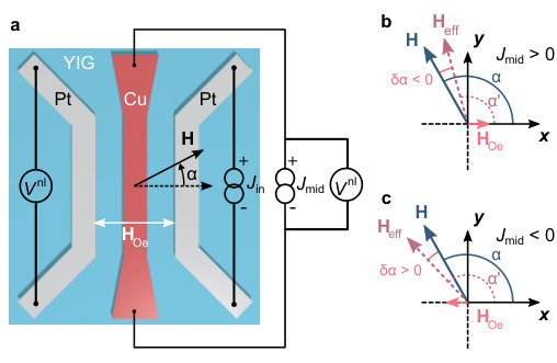 Figure 1
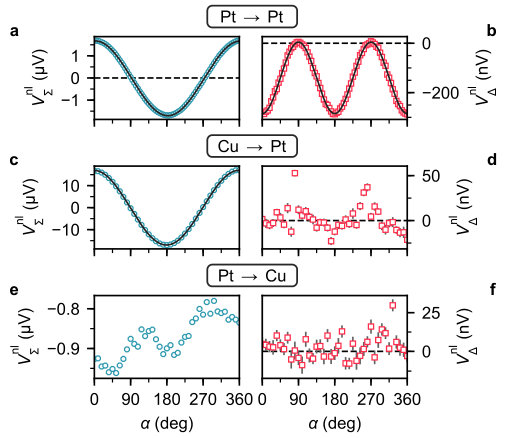 Figure 2
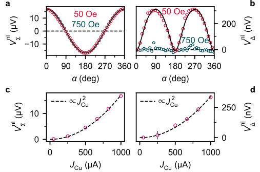 Figure 3
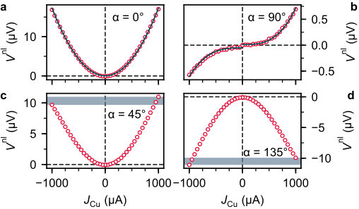 Figure 4
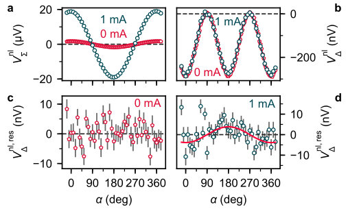 Figure 5
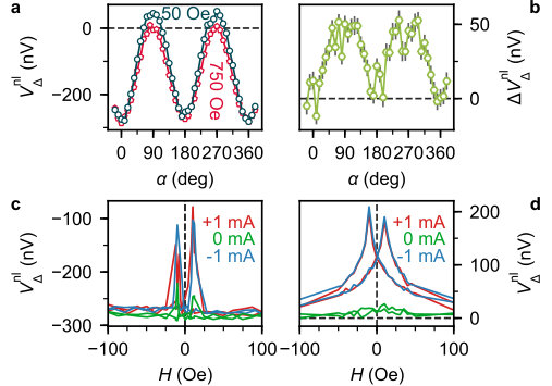 Figure 6
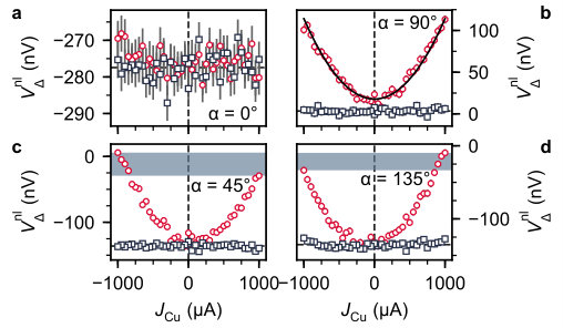 Figure 7
 Figure 8
Peer Reviews
No public reviews on file for this paper yet. If you reviewed it on a platform where reviews are public (OpenReview, ICLR, NeurIPS, ICML), you can paste yours below so the community can read it here.
Videos
No videos yet. Explain this paper in a talk, walkthrough, or lecture? Add one.
Impact of electromagnetic fields and heat on spin transport signals in Y3Fe5O12
Joel Cramer
Institute of Physics, Johannes Gutenberg-University Mainz, 55099 Mainz, Germany
Graduate School Materials Science in Mainz, 55128 Mainz, Germany
Lorenzo Baldrati
Institute of Physics, Johannes Gutenberg-University Mainz, 55099 Mainz, Germany
Andrew Ross
Institute of Physics, Johannes Gutenberg-University Mainz, 55099 Mainz, Germany
Graduate School Materials Science in Mainz, 55128 Mainz, Germany
Mehran Vafaee
Institute of Physics, Johannes Gutenberg-University Mainz, 55099 Mainz, Germany
Romain Lebrun
Institute of Physics, Johannes Gutenberg-University Mainz, 55099 Mainz, Germany
Mathias Kläui
Institute of Physics, Johannes Gutenberg-University Mainz, 55099 Mainz, Germany
Graduate School Materials Science in Mainz, 55128 Mainz, Germany
(March 19, 2024)
Abstract
Exploring new strategies to perform magnon logic is a key requirement for the further development of magnon-based spintronics. In this work, we realize a three-terminal magnon transport device to study the possibility of manipulating magnonic spin information transfer in a magnetic insulator via localized magnetic fields and heat generation. The device comprises two parallel Pt wires as well as a Cu center wire that are deposited on the ferrimagnetic insulator Y3Fe5O12. While the Pt wires act as spin current injector and detector, the Cu wire is used to create local magnetostatic fields and additional heat, which impact both the magnetic configuration and the magnons within the Y3Fe5O12 below. We show that these factors can create a non-local signal that shows similar features as compared to an electrically induced magnon flow. Furthermore, a modulation of the spin transport signal between the Pt wires is observed, which can be partly explained by thermally excited spin currents of different polarization. Our results indicate a potential way towards the manipulation of non-local magnon signals, which could be useful for magnon logic.
I Introduction
The ultimate goal of magnonicsKruglyak et al. (2010); Serga et al. (2010); Lenk et al. (2011), a research field that investigates spin wave phenomena, is the effective control and manipulation of spin wave propagation and detection in magnetic materials. This involves the implementation of magnon circuitry that is able to perform logic operations, i.e. to realize magnon based computingKhitun et al. (2010); Chumak et al. (2015). Potential advantages of this approach over conventional, charge-based concepts are the possibility to encode information in both the amplitude and phase of a spin wave for coherent logicChumak et al. (2015); Tserkovnyak and Kläui (2017) and furthermore an improved energy efficiencyKhitun et al. (2010), in particular in ferroic insulators. The latter results from the absence of Joule heating during spin wave motion and low damping parameters when using magnetic insulators as a spin wave conduitSerga et al. (2010).
To date, theoreticalKostylev et al. (2005); Klingler et al. (2014); Brächer and Pirro (2018) and experimentalChumak et al. (2014); Wagner et al. (2016); Fischer et al. (2017); Balinskiy et al. (2018) studies regarding magnon logic operations have mainly focused on schemes based on coherent spin waves effects, effectively exploiting interference phenomenaChumak et al. (2015); Tserkovnyak and Kläui (2017). This includes, for instance, devices like the all-magnon transistorChumak et al. (2014), a logic majority gateFischer et al. (2017) or an analog magnon adderBrächer and Pirro (2018). Lately, logic operations based on thermal, incoherent magnons as information carriers have gained increased interest in the course of non-local magnon transport experimentsCornelissen et al. (2015); Goennenwein et al. (2015); Lebrun et al. (2018). Through the direct and inverse spin Hall effect (SHE)Sinova et al. (2015), which appear in conductors with strong spin-orbit interaction (SOI), information transport in magnetic insulators via thermal magnons can be excited and detected electrically, interfacing magnonics and electronics. Among others, it has been successfully demonstrated that the linear superposition of diffusive magnon currents in insulators can be used to implement a majority gateGanzhorn et al. (2016). Furthermore, multi-terminal devices that exhibit transistor-like behavior have been realizedCornelissen et al. (2018); Wimmer et al. (2018). The latter rely on the local manipulation of the magnon chemical potentialCornelissen et al. (2016) and thus the magnon conductivity, which is achieved by the SHE induced injection of additional magnons through a heavy metal gate. However, applying a charge current to such a gate concurrently results in local heating and generates a magnetostatic field (Oersted field), which also might affect magnon propagation within the insulator. To study these effects exclusively, without any interference due to externally injected magnon currents, one would need to replace the heavy metal gate by a normal metal with weak SOI and, hence, a negligible SHE.
In this work, a three-terminal non-local magnon transport device including a Cu-based gating structure is implemented to investigate the modulation of magnon propagation signals in magnetic insulators via localized magnetostatic fields and heat. Magnon transport measurements in rotating magnetic fields of varying amplitude show that these perturbing forces affect the non-local signal and furthermore generate an additional voltage response with similar features as that of magnons induced by the spin Hall effect.
II Experimental details
A schematic of the implemented multi-terminal device is shown in Fig. 1a, depicting a non-local magnon transport structure that comprises three metallic nanowires on a magnetic insulator. Regarding the latter, a commercially available, single crystalline Y3Fe5O12 (YIG)Serga et al. (2010) film with a thickness of 150\text{,}\mathrm{nm} and with (111) surface orientation is used. The outer wires ($250\text{\,}\mathrm{nm}$ width and $1.1\text{\,}\mathrm{\SIUnitSymbolMicro m}$ center-to-center distance) are made of Pt ($d_{\mathrm{Pt}}=$7.5\text{\,}\mathrm{nm}), while the center strip ( width) consists of a copper layer capped by of Al to protect it from oxidation. The nanowires are patterned in a multi-step lift-off process including electron beam lithography and metal deposition via magnetron sputtering.
In the device, the Pt wires are used to both inject and detect magnonic spin currents in the YIG through the direct and inverse SHECornelissen et al. (2015); Goennenwein et al. (2015). Considering first the excitation of spin currents, the application of a charge current to one of the wires (injector) results in a spin-dependent, transverse deflection of electrons due to the SHE so that, eventually, a spin accumulation builds up at the Pt/YIG interface. The polarization vector of this spin accumulation is perpendicular to the wire and, depending on the magnetic orientation of the YIG, magnons are either created or annihilatedBender et al. (2012). As a result, an imbalance of the magnon population in the YIG is induced and a diffusive magnon spin current is flowingZhang and Zhang (2012). Concurrently, a thermally excited magnon flow generated by the spin Seebeck effect (SSE) is presentUchida et al. (2016); Ganzhorn et al. (2017) due to the Joule heating from . With regard to the detection of magnonic spin currents, these are partially absorbed by the second Pt stripe (detector) and reconverted to a detectable charge signal via the inverse SHECornelissen et al. (2015).
As mentioned above, the novelty of our device is the Cu center strip that is used here to study the modulation of the magnon transport signal between injector and detector via the generation of local heat and magnetostatic Oersted fields supplied by the charge current (see Fig. 1a). Note that, in contrast to Pt, Cu does not exhibit a sizable SHE/ISHE due to its weak SOIWang et al. (2014) such that does not result in a further spin current pumped into the YIGCornelissen et al. (2018); Wimmer et al. (2018), which would interfere with the effects studied here.
For the full characterization of the device and identification of various signal contributions, different circuitry configurations were implemented, see Fig. 1a. Spin transport between the outer Pt stripes (Pt Pt) was studied by connecting the right Pt wire (injector) to a current source supplying the DC charge current 250\text{,}\mathrm{\SIUnitSymbolMicro A} ($j_{\mathrm{Pt}}\approx$1.3\text{\times}{10}^{11}\text{\,}\mathrm{A}\text{\,}{\mathrm{m}}^{-2}) required for the electrical (SHE) or thermal (SSE) excitation of magnons in the YIG. The inverse SHE voltage drop at the detector (left Pt stripe) was picked up by a nanovoltmeter. The Cu center wire (modulator) was connected to a second current source, supplying a DC charge current of up to 1\text{,}\mathrm{mA} ($j_{\mathrm{Cu}}\leq\pm$2.29\text{\times}{10}^{11}\text{\,}\mathrm{A}\text{\,}{\mathrm{m}}^{-2}). In a second configuration, the direct response of the detector towards charge currents applied to the modulator (Cu Pt) was checked, for which the Pt injector was left unbiased (0\text{,}\mathrm{A}$$). Eventually, to verify that the Cu modulator reveals no spin-charge interconversion, it was connected to the nanovoltmeter while applying a charge current to the injector (Pt Cu). In the following, we show field and angular-dependent measurements performed by sweeping an external field or by rotating the sample in a static field (angle , see Fig. 1a). All measurements were conducted at room temperature.
Note that when implementing a DC measurement scheme as described above, electrically (SHE) and thermally (SSE) induced spin signals typically can be extracted by considering either the difference or the sum of the non-local voltages obtained for positive and negative charge currents applied to the injectorThiery et al. (2018a). In this study, such a simple distinction is not always applicable so that we use a generalized notation
[TABLE]
Here, is the charge current applied to either the Pt injector () or the Cu wire (). If an AC measurement scheme was used as in Ref. Cornelissen et al., 2015, () would correspond to the () signal.
III Results and discussion
III.1 Device functionality
First, we checked the functionality of the non-local device and especially the absence of any spin-charge conversion in the Cu wire. The Pt Pt configuration with no charge current applied to the Cu wire shown in Fig. 2a,b
reveals the angular dependences expected for thermally [] and electrically [] excited magnon currents, in agreement with the spin current excitation and detection modelZhang and Zhang (2012); Bender et al. (2012). These dependences arise from the (I)SHE symmetry, which yields maximum injection and detection signals when the YIG magnetization is parallel to the spin accumulation , while being zero for perpendicular alignment. The non-local voltage obtained for the Cu Pt configuration, i.e. the spin signal generated when injecting a charge current into the Cu modulator, is now shown in Fig. 2c,d. The current-induced Joule heat gives rise to the non-local SSE, as captured by , while fluctuates around zero. This is expected as Cu does not exhibit a significant SHEWang et al. (2014). The higher amplitude of in Fig. 2c as compared to that in Fig. 2a is due to the smaller wire distance and stronger Joule heating (6.40\text{,}\mathrm{mW} vs. $\approx$0.73\text{\,}\mathrm{mW}). Moreover, the results depicted in Fig. 2e,f (Pt Cu configuration) additionally corroborate the absence of spin-charge conversion in Cu. fluctuates around zero, while shows a finite, oscillating and slightly increasing voltage. The geometry of this last signal, however, does not correspond to the one of the SSE and therefore must be of different origin (e.g. conventional Seebeck effect and fluctuating sample temperature in our thermally non-isolated setup).
These results demonstrate the current-induced spin transport between the outer Pt stripes and the absence spin-charge conversion within the Cu wire. The latter information is crucial for the following discussion.
III.2 Spin signal excitation via the Cu wire
In this section, we now consider the effect of magnetostatic Oersted fields at the modulator, which are generated by Coey (2010):
[TABLE]
where describes a closed integrating path around the Cu modulator (-plane). Charge currents applied to the nanowires flow along the -direction (see Fig. 1) such that exclusively exhibits - and -components. Here, only the -component is of interest considering a relatively strong easy plane shape anisotropy of the thin YIG film. According to Eq. 3, results in a positive Oersted field underneath the Cu wire (-component in \alpha=$$$ direction), while J_{\mathrm{Cu}}<0\alpha=). For the following discussions, it is useful to consider an effective field $\boldsymbol{\mathbf{H}}_{\mathrm{eff}}=\boldsymbol{\mathbf{H}}+\boldsymbol{\mathbf{H}}_{\mathrm{Oe}}$ at an angle $\alpha^{\prime}=\alpha+\delta\alpha$, which locally acts on the YIG magnetization. As sketched in Fig. [1](#S2.F1)b,c, the angular shift $\delta\alpha$ is negative for <\alpha<and $J_{\mathrm{Cu}}>0$, while being positive for $J_{\mathrm{Cu}}<0$. In the range of<\alpha<$$$, the opposite occurs.
Finite element simulations (see Supporting Information) show that for the maximum current 1\text{,}\mathrm{mA} a field amplitude of $H_{\mathrm{Oe},x}\approx\pm$14\text{\,}\mathrm{O}\mathrm{e} is induced at the wire center, directly at the YIG/Cu interface. The external field applied during the angular-dependent measurements of Fig. 2, however, was much larger (750\text{,}\mathrm{O}\mathrm{e}$$) such that the additional torque exerted on the YIG magnetization by the Oersted field can be considered negligible. Note that the magnitude of exhibits a strong spatial variation, so that the net effect of the Oersted field on the YIG magnetization configuration is hereafter discussed qualitatively rather than quantitatively, for which further simulations would be necessary.
To probe the impact of the Oersted field, the angular-dependent measurements in the Cu Pt configuration were repeated at a reduced external field of 50\text{,}\mathrm{O}\mathrm{e}$$, which is enough for the YIG magnetization to follow the field direction (see Supporting Information). As shown in Fig. 3a, does not modulate , which stems from the conventional non-local SSE.
This appears reasonable, as is even in the direction of and potential effects by the Oersted field are averaged out. , on the other hand, is odd in the direction of and a distinct, angular-dependent signal is recorded for 50\text{,}\mathrm{O}\mathrm{e}$$. The symmetry of the signal does not agree with the one of electrically (SHE) injected spin currents, however it can be fitted by an adjusted function, yielding an amplitude of . The definition of this function is discussed in the Supporting Information, based on the findings shown below.
To demonstrate the origin of the signal, we measured the angular dependence for different applied to the modulator. Considering first (Fig. 3c), we see a quadratic current dependence as expected for spin currents generated by the SSEThiery et al. (2018a). Likewise, fitting the data yields a quadratic dependence of the amplitude, see Fig. 3d. While this indicates a thermal origin of , one also has to bear in mind the direction of and the induced angular shift as a function of the applied charge current . The largest is expected for \alpha=$$,\,$$$, where the x\alpha=$$,, on the other hand, $\delta\alpha= is anticipated as . To verify this behavior, the current dependence of the raw voltage is shown in Fig. 4 for different magnetization directions. In these measurements, the external field was used to align at an desired angle and switched off afterwards (remanent state of YIG) to observe the pure impact of the Oersted field.
Considering first \alpha=$$$, one can see in Fig. [4](#S3.F4)a that V^{\mathrm{nl}}J_{\mathrm{Cu}}, as expected for thermally excited signalsThiery *et al.* ([2018a](#bib.bib29)). The symmetry of the voltage furthermore verifies that the additional Oersted field has no effect. Remarkably, for \alpha= $V^{\mathrm{nl}}$ exhibits an asymmetric, cubic current dependence, see Fig. [4](#S3.F4)b. This asymmetry immediately demonstrates the importance of the Oersted field: the positive voltage for $J_{\mathrm{Cu}}>0$ corresponds to a non-local SSE signal at $\alpha^{\prime}<, while yields \alpha^{\prime}>$$$ and thus a negative SSE voltage. The relevance of \boldsymbol{\mathbf{H}}{\mathrm{Oe}}becomes further evident in Fig. [4](#S3.F4)c,d, respectively, in which\boldsymbol{\mathbf{M}}{\mathrm{YIG}}\alpha= and $\alpha=. The opposite voltage signs signify the reversed -components of and thus the reversed polarization of magnonic spin currents flowing, whereas the inverted asymmetries regarding corroborate the Oersted field effect. At \alpha=$$$, a positive (negative) J_{\mathrm{Cu}}\alpha^{\prime}< ($\alpha^{\prime}>), yielding different amplitudes. For $\alpha=$$$, similar considerations can be made.
As a first conclusion, we have shown that the finite voltage signal , which appears at low or zero external fields applied, measures the difference between the -components of thermally excited magnonic spin currents. The ISHE in the Pt detector is sensitive to this variation, induced by the influence of the reversed Oersted fields. Such fields can have significant impact at low external field amplitudes (\delta\alpha\neq$$$), whereas V^{\mathrm{nl}}{\mathrm{\Delta}}\boldsymbol{\mathbf{H}}{\mathrm{eff}}\simeq\boldsymbol{\mathbf{H}}J_{\mathrm{Cu}}$ amplitudes used in this work.
Besides the discussed asymmetries, this model also explains the cubic current dependence of on in Fig. 4b. As mentioned before, the non-local SSE voltage is proportional to the Joule heat generated by the Cu wire () and to the -component of the YIG magnetization :
[TABLE]
At $\alpha=$$$, this yields
[TABLE]
for small . Moreover, at this angle the -component of the effective field is exclusively provided by such that, according to Eq. 3, and
[TABLE]
Among other things, the proportionality factor in Eq. 6 is determined by the amplitude of the external field.
Taken all together, these results demonstrate that even when using a metal wire with negligible SOI, a finite can appear. In contrast to a heavy metal injector, this voltage is not given by SHE induced spin currents, but results from different -components of thermal spin currents generated in the presence of opposite Oersted fields. Thus, when interpreting in general, multiple mechanisms need to be analyzed.
III.3 Impact of heat and Oersted fields on spin transport signals
As described in the introduction, the actual aim of this work is to modulate the spin information exchange between heavy metal wires by the heat and Oersted fields generated by the Cu center wire. Focusing first on the impact of Joule heating, angular-dependent measurements implementing the Pt Pt configuration (see Fig.2a,b) have been performed, once with and without a charge current applied to the Cu wire (0\text{,}\mathrm{mA}1\text{,}\mathrm{mA}). To suppress any influence of the Oersted field, the sample was rotated in an external field of $H=$750\text{\,}\mathrm{O}\mathrm{e}. As shown in Fig. 5a, the variation of for different is trivial: Due to the additional heat, the signal amplitude is significantly enhanced. This result emphasizes that, by definition, accounts for thermally excited magnons that are generated near the Pt injector and the Cu modulator. Instructive information on potential modulations of the spin transport mechanism between the Pt wires is thus only provided by , for which the modulator contributions average out. Therefore, is disregarded in the following.
Figure 5b shows as a function of , for zero and finite . At first sight, it seems that the charge current through the Cu wire yields no modification of the spin transport signal. For both 0\text{,}\mathrm{mA} and $J_{\mathrm{Cu}}=+$1\text{\,}\mathrm{mA} the expected angular dependence [] is observed and similar signal amplitudes are obtained: V^{\mathrm{nl}}_{\mathrm{\Delta}}\left(0\text{,}\mathrm{mA}\right)=-282\pm 5\text{,}\mathrm{nV} and $V^{\mathrm{nl}}_{\mathrm{\Delta}}\left(+$1\text{\,}\mathrm{mA}$\right)=$-280\pm 4\text{\,}\mathrm{nV}. To nevertheless identify potential smaller deviations from the conventional spin transport signal, the experimental data was fitted by a correpsonding function and the resultant curve was subtracted from the data. The calculated residuals are displayed in Fig. 5c,d. For zero applied charge current (Fig. 5c), the residuals fluctuate around without distinct angular dependence, as expected. For 1\text{,}\mathrm{mA}$$ (Fig. 5d), however, a variation of as a function of appears. Assuming the symmetry of the signal, the data is fitted phenomenologically by a cosine function, yielding a modulation amplitude of . To check the unambiguity of this modulation, the reduced methodHughes and Hase (2010) is applied, which allows one to evaluate whether the data is consistent with the proposed model or if the model is to be rejected. For the cosine function, a reduced chi-squared of is calculated, implying that it describes the data wellHughes and Hase (2010). The alternative model of no signal modulation (horizontal line) yields and thus can be rejected Hughes and Hase (2010). One therefore can speculate whether the diffusive SSE current, whose polarization is determined by the rotating magnetization , interacts with the electrically induced magnons propagating in the systemWimmer et al. (2018). To obtain a better understanding of this effect and to explain the observed angular dependence quantitatively, further experimental as well as theoretical work is required. Finally, note that the Joule heat emitted by the Cu modulator entails a local reduction of the YIG magnetization due to the enhanced temperaturesGilleo and Geller (1958). This can result in a generally decreased amplitude of , which however is not observed for the charge current densities applied in this work.
Finally, the influence of the Oersted field generated by the Cu modulator on the spin transport signal was investigated. As done before, angular-dependent measurements were repeated at high and low external magnetic fields, now with a fixed 1\text{,}\mathrm{mA}$$. In Fig. 6a, is shown as a function of and for two different external fields (red pentagons: , blue circles: ).
The signals exhibit similar symmetries and for \alpha=$$$/[math]/[math], at which external and Oersted field are parallel, they furthermore have equal amplitudes. At \alpha= and $\alpha= (external and Oersted field perpendicular), however, deviates being zero at and exhibiting a finite, positive value at . To highlight this discrepancy, the signal difference \Delta V^{\mathrm{nl}}_{\mathrm{\Delta}}=V^{\mathrm{nl}}_{\mathrm{\Delta}}\left(50\text{,}\mathrm{O}\mathrm{e}\right)-V^{\mathrm{nl}}_{\mathrm{\Delta}}\left(750\text{,}\mathrm{O}\mathrm{e}\right) is shown in Fig. 6b. At first sight, this result might suggest that the spin (magnon) conductance of the YIG layer is altered by the Oersted field. In a simple picture, cants away from the \alpha=$$/$$$ direction, at which magnons cannot be injected or detected by the Pt wires due to the (I)SHE symmetrySinova *et al.* ([2015](#bib.bib18)). If \boldsymbol{\mathbf{H}}{\mathrm{Oe}}x\boldsymbol{\mathbf{M}}{\mathrm{YIG}}\Delta V^{\mathrm{nl}}{\mathrm{\Delta}}in Fig. [6](#S3.F6)b contradicts this interpretation. For the realized device structure with equal injector and detector wire material, the electrically induced non-local voltage must be negativeGoennenwein *et al.* ([2015](#bib.bib16)). SHE induced magnon flow may still be present, however the sign of\Delta V^{\mathrm{nl}}{\mathrm{\Delta}}$ implies a different, dominating effect that we discuss below.
To investigate the source of , field and current sweep measurements were performed. Regarding the field dependence, Fig. 6c,d shows as a function of and for \alpha=$$$ (Fig. [6](#S3.F6)c) and \alpha= (Fig. [6](#S3.F6)d). The vertical solid lines mark the switching fields $H^{\pm}_{\mathrm{c}}$ of the YIG layer (see Supporting Information). At $\alpha=, the non-local voltage is mainly field-independent except for signal peaks near (reduced absolute voltage). These peaks are due to the YIG magnetization reversal and the associated formation of magnetic domains, whose random magnetization alignments impede the propagation of magnon spin currents. For non-zero , the peaks are broader and of larger amplitude as compared to , implying a more pronounced domain formation due to thermal activation or the presence of the Oersted field. More specific information is revealed when considering \alpha=$$$ in Fig [6](#S3.F6)d. In the case of J_{\mathrm{Cu}}=0\text{\,}\mathrm{mA}$$, V^{\mathrm{nl}}{\mathrm{\Delta}}J{\mathrm{Cu}}=\pm1\text{\,}\mathrm{mA}$$, however, a significant voltage signal appears, whose amplitude becomes largest at the coercive fields of the YIG layer. Irrespective of the polarity of J_{\mathrm{Cu}}\boldsymbol{\mathbf{H}}{\mathrm{Oe}}V^{\mathrm{nl}}{\mathrm{\Delta}}$ exhibits a positive sign so that it cannot be directly assigned to SSE currents generated underneath the Cu modulator (compare to previous results, e.g. Fig. 4b).
To understand this, the current () dependence of is checked in Fig. 7 for different magnetization angles and external fields (large vs. zero field).
Recall that has no direct influence on the magnitude of the spin current excited electrically in the Pt injector. Comparable to the results presented before (e.g. Fig. 3b), exhibits no change with at high fields (, blue squares) for all magnetization directions. This further holds true for zero field and \alpha=$$$ (Fig. [7](#S3.F7)a). At \alpha=, however, $V^{\mathrm{nl}}_{\mathrm{\Delta}}$ exhibits a symmetric increase with current amplitude when no field is applied (red pentagons), see Fig. [7](#S3.F7)b. The data is fitted well by a quadratic function (solid line), which points towards a thermal origin. For $\alpha= and $\alpha=$$$ (Fig. 7c,d) the zero-field signals grow with opposite asymmetry.
With this information, one can develop a model to explain the occurence of at low/zero fields and finite charge currents applied to the Cu modulator. At first, one has to consider that the Joule heat generated by is not locally restricted but diffuses in the sample. The phonon propagation length in YIG is of the order of several hundred micrometer Boona and Heremans (2014) so that the thermal equilibrium of the system is also strongly disturbed underneath the Pt injector (and detector). Furthermore, the charge current applied to the injector as well creates local Oersted fields. One can thus conclude that the signal modulation is due to a difference between the -components of thermally excited magnonic spin currents underneath the Pt injector. It thus has the same origin as the non-local signal observed in the first part of this study (Cu Pt, Fig. 3b), which is corroborated by the similar symmtries of in Fig. 3b and shown in Fig. 6b.
In addition to the heat provided by the Cu modulator, the asymmetry of in Fig. 7c,d signifies that the Oersted field generated by as well influences the recorded signal. Regarding first \alpha=$$$, recall that J_{\mathrm{Cu}}>0\alpha^{\prime}=$$+\delta\alpha<. For $J_{\mathrm{Cu}}<0$, we find $\alpha^{\prime}>. At the position of the Pt injector, this deflection of the YIG magnetization is further strengthened or weakened by the Oersted field induced by , depending on its polarity. Now, based on the fact that is the voltage difference for positive and negative , not the amplitude but the slope of the original non-local SSE signal at is decisive. The latter follows a symmetry, such that
[TABLE]
holds. One therefore expects a smaller for as compared to , which agrees with the data shown in Fig. 7c. The inversed asymmetry for $\alpha=$$$ in Fig. 7d can be explained by an analogous argumentation.
Altogether, these results demonstrate that the additional Joule heat and the Oersted fields provided by the Cu center wire indeed can be used to modulate the transport signal of electrically excited magnons. As a final remark, note that YIG exhibits an exponentially decreasing electrical resistivity when exposed to strong resistive heating (300\text{,}\mathrm{K}$$)Thiery et al. (2018b) such that electrically transmitted voltages may interfere with magnon mediated signals. This effect may become important for large charge currents applied to the nanowires, nevertheless it cannot explain the distinct field and angular dependences observed in this work, which is why we can rule out charge transport effects as the dominating factor here.
III.4 Conclusion
In summary, the influence of localized heating and Oersted fields on magnonic spin transport signals in the insulating ferrimagnet YIG were investigated by using a non-local device structure with an additional Cu wire used to locally generate a field or induce a temperature change. First experiments demonstrate that the exclusive application of a charge current to the Cu modulator generates a signal response, which exhibits similar features as SHE induced magnon flow. The data reveals that this signal results from thermally excited magnons with different polarization.
A similar effect is observed when investigating the impact of the additional heat and Oersted fields on the spin transport signal between the outer Pt wires. At small external fields, thermally induced magnon flow with different magnon polarization superimposes the conventional voltage response induced by electrically excited magnons. A further modulation of the transport signal is observed at large external fields, for which the effect of is suppressed. This may be due to interference of the electrically excited magnon current with thermally activated magnons, however, further theoretical and experimental work (e.g. different non-local device geometries) is required to explain this observation quantitatively.
Overall, the results show that the magnon transport signal in a spin conduit such as YIG can be moduluated by localized heating and electromagnetic fields, which might find application in the field of magnon logic.
IV Acknowledgments
We kindly acknowledge support by the Deutsche Forschungsgemeinschaft (DFG) (SPP 1538 Spin Caloric Transport, SFB TRR173 SPIN+X in Mainz), the Graduate School of Excellence Materials Science in Mainz (DFG/GSC 266), and the EU project INSPIN (FP7-ICT-2013-X 612759). L.B. acknowledges the EuropeanUnion’s Horizon 2020 research and innovation program underthe Marie Skłodowska-Curie Grant Agreement ARTES No.793159. R.L. acknowledges the European Union’s Horizon2020 research and innovation programme under the Marie Skłodowska-Curie Grant Agreement FAST No. 752195.
The reference list from the paper itself. Each links out to its DOI / PubMed record.
- 1Kruglyak et al. (2010) V. V. Kruglyak, S. O. Demokritov, and D. Grundler, J. Phys. D: Appl. Phys. 43 , 264001 (2010) . · doi ↗
- 2Serga et al. (2010) A. A. Serga, A. V. Chumak, and B. Hillebrands, J. Phys. D: Appl. Phys. 43 , 264002 (2010) . · doi ↗
- 3Lenk et al. (2011) B. Lenk, H. Ulrichs, F. Garbs, and M. Münzenberg, Phys. Rep. 507 , 107 (2011) . · doi ↗
- 4Khitun et al. (2010) A. Khitun, M. Bao, and K. L. Wang, J. Phys. D: Appl. Phys. 43 , 264005 (2010) . · doi ↗
- 5Chumak et al. (2015) A. V. Chumak, V. I. Vasyuchka, A. A. Serga, and B. Hillebrands, Nat. Phys. 11 , 453 (2015) . · doi ↗
- 6Tserkovnyak and Kläui (2017) Y. Tserkovnyak and M. Kläui, Physical Review Letters 119 , 187705 (2017) . · doi ↗
- 7Kostylev et al. (2005) M. P. Kostylev, A. A. Serga, T. Schneider, B. Leven, and B. Hillebrands, Appl. Phys. Lett. 87 , 153501 (2005) . · doi ↗
- 8Klingler et al. (2014) S. Klingler, P. Pirro, T. Brächer, B. Leven, B. Hillebrands, and A. V. Chumak, Appl. Phys. Lett. 105 , 152410 (2014) . · doi ↗