Shear-induced contact area anisotropy explained by a fracture mechanics model
A. Papangelo, J. Scheibert (LTDS), R. Sahli (LTDS), G. Pallares, (LTDS), M. Ciavarella

TL;DR
This paper develops a fracture mechanics model to explain shear-induced anisotropy in adhesive contact areas, validated against experimental data, and predicts the influence of punch geometry on contact behavior.
Contribution
It introduces a novel fracture mechanics model with mode-mixity functions to describe anisotropic contact behavior under shear, extending previous adhesion models to elliptical contacts.
Findings
Model accurately predicts experimental observations.
Punch geometry influences contact area shape and decay.
Mode-mixity functions effectively describe mode coupling.
Abstract
This paper gives a theoretical analysis for the fundamental problem of anisotropy induced by shear forces onan adhesive contact, discussing the experimental data of the companion Letter. We present a fracture mechanicsmodel where two phenomenological mode-mixity functions are introduced to describe the weak couplingbetween modes I and II or I and III, which changes the effective toughness of the interface. The mode-mixityfunctions have been interpolated using the data of a single experiment and then used to predict the behavior of thewhole set of experimental observations. The model extends an idea by Johnson and Greenwood, to solve purelymode I problems of adhesion in the presence of a nonaxisymmetric Hertzian geometry, to the case of ellipticalcontacts sheared along their major or minor axis. Equality between the stress intensity factors and their criticalvalues is imposed solely at…
Click any figure to enlarge with its caption.
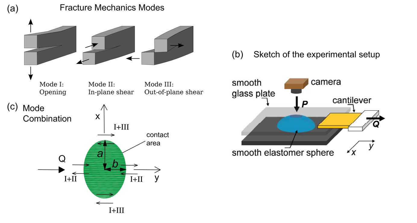 Figure 1
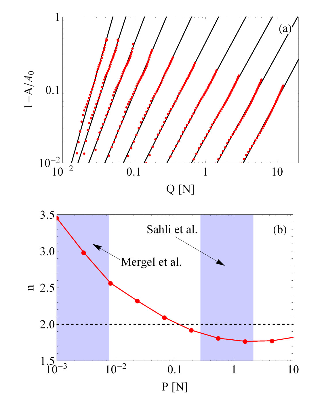 Figure 10
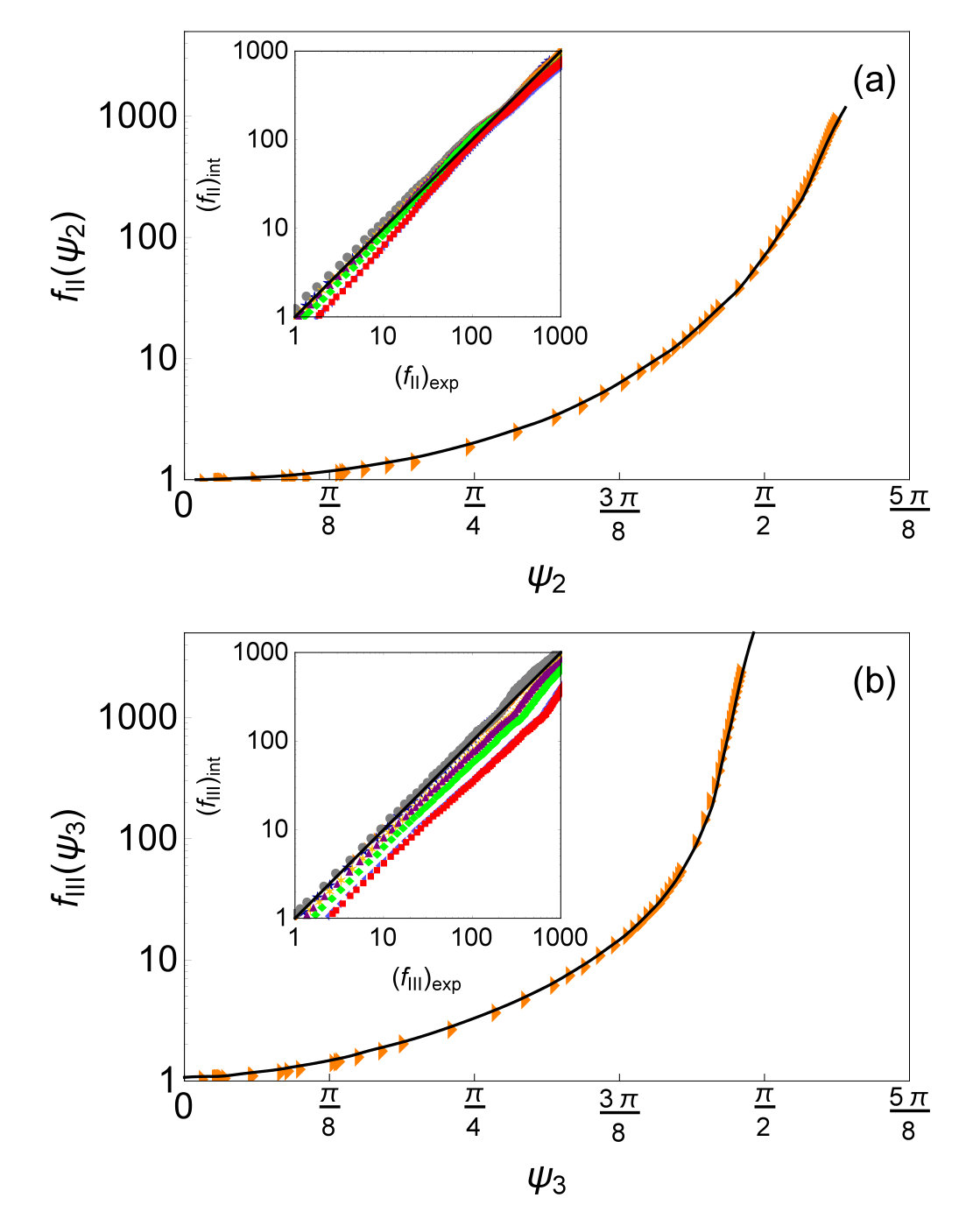 Figure 2
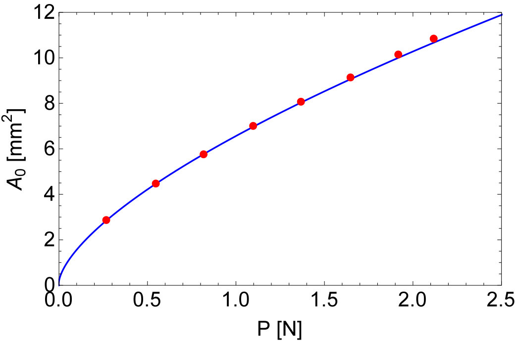 Figure 3
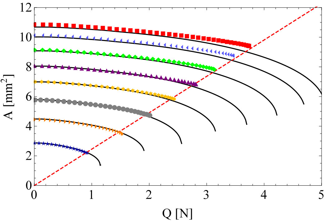 Figure 4
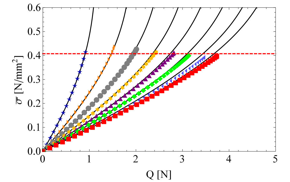 Figure 5
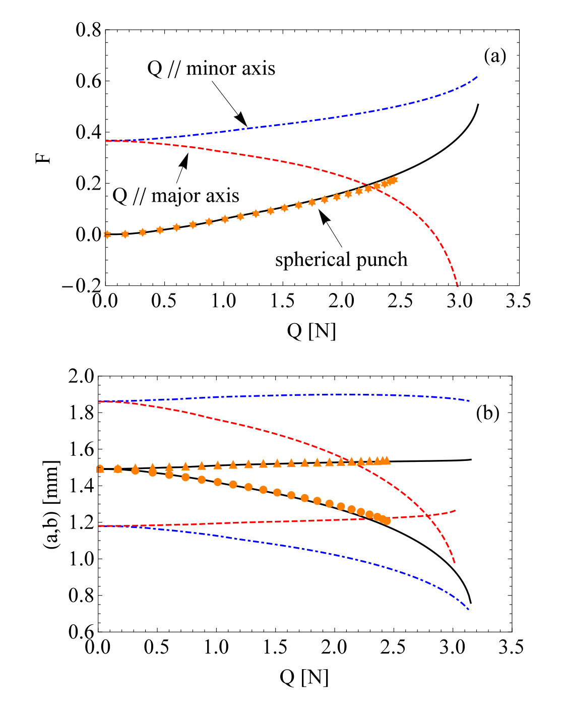 Figure 6
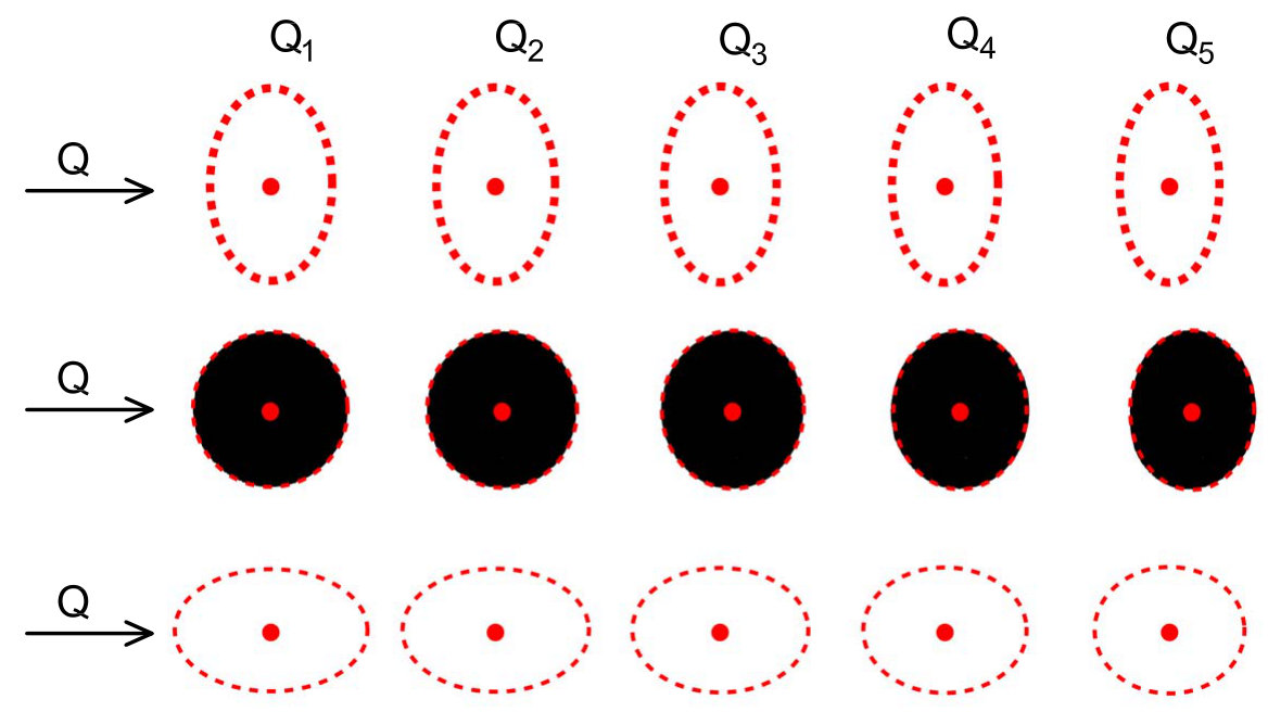 Figure 7
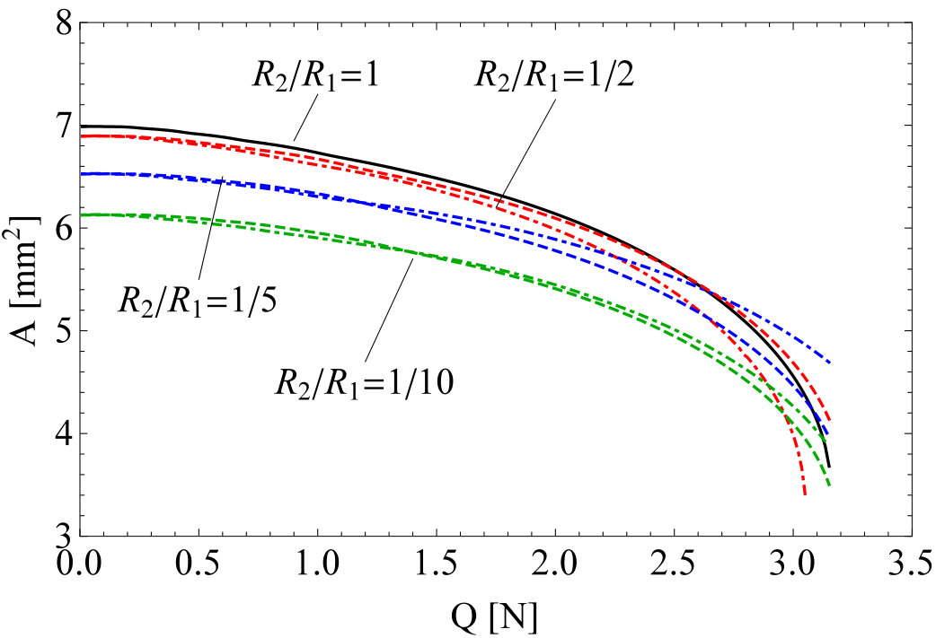 Figure 8
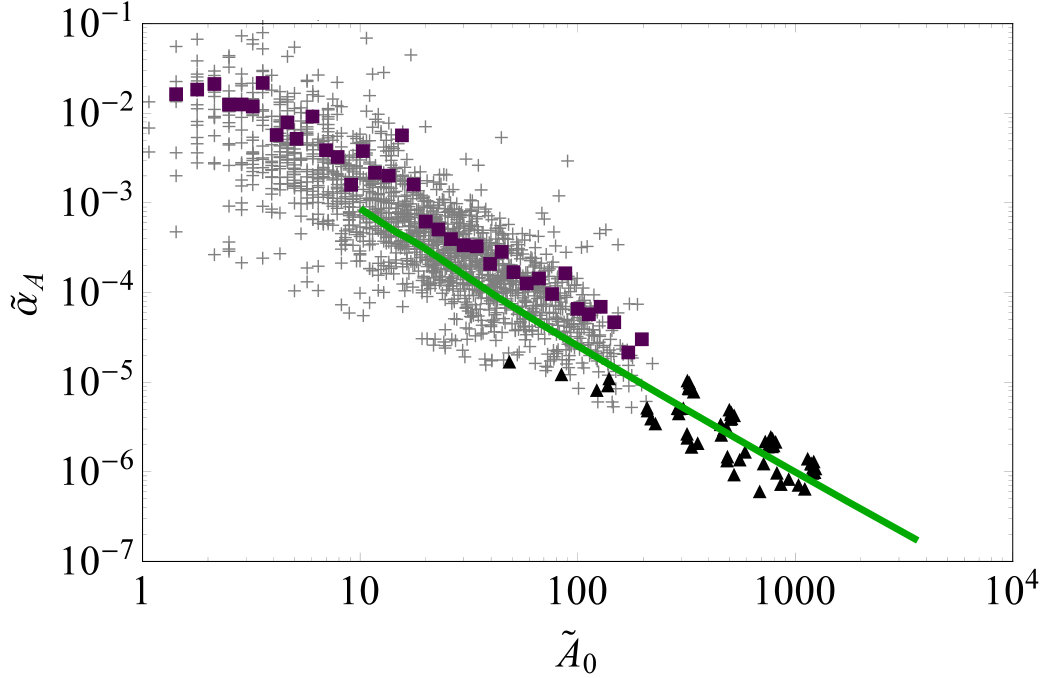 Figure 9
Peer Reviews
No public reviews on file for this paper yet. If you reviewed it on a platform where reviews are public (OpenReview, ICLR, NeurIPS, ICML), you can paste yours below so the community can read it here.
Videos
No videos yet. Explain this paper in a talk, walkthrough, or lecture? Add one.
Shear-induced contact area anisotropy explained by a fracture
mechanics model
A. Papangelo
Dipartimento di Meccanica, Matematica e Management, Politecnico di Bari, Viale Japigia 182, 70126 Bari, Italy
Hamburg University of Technology, Department of Mechanical Engineering, Am Schwarzenberg-Campus 1, 21073 Hamburg, Germany
J. Scheibert
Univ Lyon, Ecole Centrale de Lyon, ENISE, ENTPE, CNRS, Laboratoire de Tribologie et Dynamique des Systèmes LTDS, UMR 5513, F-69134, Ecully, France
R. Sahli
Univ Lyon, Ecole Centrale de Lyon, ENISE, ENTPE, CNRS, Laboratoire de Tribologie et Dynamique des Systèmes LTDS, UMR 5513, F-69134, Ecully, France
G. Pallares
Univ Lyon, Ecole Centrale de Lyon, ENISE, ENTPE, CNRS, Laboratoire de Tribologie et Dynamique des Systèmes LTDS, UMR 5513, F-69134, Ecully, France
CESI, LINEACT, Zone Aéroportuaire Méditerranée, 34130 Mauguio, France
M. Ciavarella
Dipartimento di Meccanica, Matematica e Management, Politecnico di Bari, Viale Japigia 182, 70126 Bari, Italy
Hamburg University of Technology, Department of Mechanical Engineering, Am Schwarzenberg-Campus 1, 21073 Hamburg, Germany
Abstract
This paper gives a theoretical analysis for the fundamental problem of anisotropy induced by shear forces on an adhesive contact, discussing the experimental data of the companion Letter. We present a fracture mechanics model where two phenomenological mode-mixity functions are introduced to describe the weak coupling between modes I and II or I and III, which changes the effective toughness of the interface. The mode-mixity functions have been interpolated using the data of a single experiment and then used to predict the behaviour of the whole set of experimental observations. The model extends an idea by Johnson and Greenwood, i.e. to solve purely mode I problems of adhesion in the presence of a non-axisymmetric Hertzian geometry, to the case of elliptical contacts sheared along their major or minor axis. Equality between the stress intensity factors and their critical values is imposed solely at the major and minor axes. We successfully validate our model against experimental data. The model predicts that the punch geometry will affect both the shape and the overall decay of the sheared contact area.
PACS numbers
81.40.Pq, 68.35.Np, 62.20.Qp
pacs:
Valid PACS appear here
I Introduction
The interplay of adhesion and friction is a problem of fundamental importance in tribology, which ideally should be solved at all scales from tectonic plates to atomic scales (for a recent review of multiscale methods and problems in tribology, see Vakis ). In the particular case of soft materials, it is already relatively well understood and plays a substantial role in Nature: in many insects, for example, an equivalent of an ”adhesive Coulomb friction law” has been described, whereby the normal force to detach the adhesive ”pads” is proportional to the shear force simultaneously applied (Autumn , Labonte , Gravish ). For soft materials, a finite contact area is observed also under zero force due to adhesion JKR and as a consequence, friction is measured also under vanishing or even negative normal forces Homola Yoshua . There is no unique framework to study this interaction Mergel : for instance for hard materials, although no macroscopic adhesion is found and friction may have a number of origins, Rabinowicz rabino Rabino1992 attempted to describe friction in terms of surface energy. Another example is the onset of sliding, for which fracture-like surface energy concepts have been used successfully Svet ,pap2015 ,papa12015 .
Here, we consider typically soft materials, for which the first fracture mechanics model and experiment for adhesion and friction interaction was conceived for macroscopic smooth spheres by Savkoor & Briggs Savkoor , who extended the Johnson-Kendall-Roberts (JKR) model JKR to the presence of tangential force. This model however corresponded to a ”purely brittle” model where the frictional resistance was neglected and, as such, greatly underestimated the interfacial toughness. In that respect, it has been observed that when mode I combines with mode II or/and mode III (see Fig. 1a), the interfacial toughness is greatly increased. The physical explanations for this increase are various (e.g. friction, plasticity, dislocation emission) and cannot be ascribed to a single phenomenon Hutch1990 . Since then, a few phenomenological models have been proposed (Joh1996 ,Johnson1997 ,WG2010 ,Popov1 ,Filippov1 ,Ciavafacta ,Pap2019 ) which require a Mode-Mixity Function (MMF) Hutc1992 to describe the critical condition for propagation
[TABLE]
where is mode I critical factor (or surface energy, if we assume Griffith’s concept), G_{c}\is the critical energy release rate in mixed mode conditions and finally is the ”phase angle”
[TABLE]
being , and respectively the mode III, mode II and mode I stress intensity factors.
The most recent model in this field is perhaps that by Papangelo & Ciavarella Pap2019 who compared it with recent experimental measurements by Mergel et al. Mergel , and concluded that the transition to sliding is very sensitive to the choice of the mode-mixity function. Papangelo & Ciavarella’s mode-mixity model Pap2019 suggests that upon shearing the contact can experience either a smooth transition from the JKR to the Hertzian contact area or an unstable jump to the Hertzian solution where lighter normal forces favour the latter behaviour. All Linear Elastic Fracture Mechanics (LEFM) models indicate a decay of the contact area with force, but the overall evolution strongly depends on the effective form of the MMF Pap2019 . Furthermore, the most up to date experimental evidences show that for high normal forces, the decay of the contact area with the tangential force is quadratic Sahli , while for small normal forces Mergel it isn’t. Experimental measurements of contact area evolution show that the shape of contact area is circular, according to JKR theory, at zero tangential force and shrinks in an elliptical-like fashion while the shear force is increased (Mergel , Sahli , WG2010 ). So far, all LEFM models proposed (Savkoor ,Joh1996 ,Johnson1997 ,WG2010 ,Ciavafacta ,Pap2019 ) make the approximation to consider the contact as circular, even when sheared. This requires an averaging of the effects of mode II and mode III around the periphery. However, it is well known that sphere/plane contacts loose their initial circularity when submitted to shear, indicating that axisymmetry is a very questionable assumption. Note that recent experimental investigations for rough interfaces composed of many asperities Sahli have showed similar anisotropic real area reduction and morphology changes, as discussed extensively in the companion Letter Letter . A better understanding of the simpler sphere/plane contacts is crucial to comprehend shear induced-anisotropy in rough contacts.
In the present paper, we shall extend the axisymmetric theory to include the case of elliptical shrinking of single contact area with the shear force, starting from either circular or even already elliptical contact area. Initial ellipticity typically occurs in the case of rough contacts, where most summits are mildly elliptical, the most common ratio of principal summit curvatures being near 2:1 G2006 .
The only assumption we make for simplicity is that either the major or the minor axis of the contact ellipse is aligned with the shear force: results will show a sufficiently clear overall picture. In the first part of the manuscript the theoretical model will be introduced, while in the second part it will be validated against the experimental results provided in the companion Letter Letter and in Sahli et al. Sahli .
II The approximate JKR theory for elliptical contacts
In absence of tangential force, Johnson and Greenwood JG (JG in the following) developed an approximate JKR theory for adhesion of an Hertzian profile with differing principal radii of curvature. The contact problem is solved ”approximately” in a sense that the equality of the Stress Intensity Factor (SIF) to its critical value round the periphery is only satisfied at the major and minor axis of the contact ellipse. JG assume a pressure distribution equal to
[TABLE]
where and are respectively the major and minor semi-axes of the ellipse, are constants to be found and is taken positive (negative) when compressive (tensile). The stress intensity factors at the major and minor axis (respectively and ) are
[TABLE]
JG impose the SIF at the major and minor axis to be equal to its critical value which, by standard LEFM arguments, is , where is the plane strain composite modulus of the interface, and the mode I ”toughness” or surface energy. Galin’s Galin theorem establishes that any pressure distribution of the form (4) produces a field of quadratic displacements
[TABLE]
where is the indentation and are constants to be found. Kalker Kalker reveals the relation between the sets of constants and
[TABLE]
where are complete elliptic integrals of argument with and are the principal radii of curvature. The problem is closed adding the equation for the total normal force
[TABLE]
or for the indentation Kalker
[TABLE]
which, in the original case of JG, closes the system of 5 equations (5,6,8,9 (or 10)) in the 5 unknowns . For this corresponds to the classical JKR solution.
III The effect of tangential force
III.1 Theoretical model
Assume that we have a sphere of radius in adhesive contact with a halfspace (see Fig. 1b).
If a tangential shearing force is applied, and no slip occurs in the contact area, a singular shear traction distribution of the form
[TABLE]
will arise at the interface. Experimental inspection of contact area in this condition shows the contact patch is nearly elliptical and shrinks along the direction of the applied shearing force (mode II), while remaining slightly affected in the perpendicular direction (mode III) (see sketch Fig. 1c, the companion Letter Letter , Sahli , Mergel and WG2010 ). A shear traction distribution of the form (11) gives a tangential force and produces at the major axis and while at the minor axis, . The energy release rate according to standard Fracture Mechanics arguments is , thus using (5,6) the equivalent SIF at the major ”” and minor ”” axes are
[TABLE]
The critical energy needed for the external crack to advance, , depends on the ”mode-mixity”. Following Hutchinson & Suo Hutc1992 we shall postulate that depends on the phase angles and , thus at the minor (where we have modes I and II) and major (where we have modes I and III) axes we write respectively and i.e.
[TABLE]
where and are two MMFs which take into account the mixed-mode dependent toughness of the interface.
To sum up, the problem is reduced to a system of equations in the unknown 111The last equation for the force can be replaced by the respective for indentation (10).
[TABLE]
where, if the punch is axisymmetric222In deriving the model we start with the case of a sheared spherical punch. Nevertheless the model can be also used for non-axisymmetric Hertzian geometry provided that the tangential force is aligned with the minor or major axis. . In principle, if one knows how the interfacial toughness depends on the mode combination, this problem can be solved exactly, with the sole approximation that the equality of the SIFs with their critical values is guaranteed only at the major and minor axes in line with JG approximation.
Next, the following dimensionless notation is introduced Maugis
[TABLE]
and the system of eq. (16) is written in dimensionless form
[TABLE]
where we used . If, in place of the normal force , the normal indentation is controlled, the last equation in (18) is replaced by
[TABLE]
For a tangential displacement controlled experiment we recall that an elliptical shear distribution as in (11) produces a uniform tangential displacement equal to Joh1985
[TABLE]
where we used the identity and In dimensionless form gives
[TABLE]
so that may be replaced by in (18).
Although the theoretical model has been derived with the hypothesis of having the tangential force aligned with the minor axis (y direction in Fig. 1b and c), it can be trivially rewritten with aligned with the major axis.
III.2 Mode-mixity function estimation
As shown in Papangelo & Ciavarella Pap2019 for the axisymmetric case, the model results are very sensitive to the exact choice of the phenomenological mode-mixity function. After testing the Literature models available, e.g. the models proposed by Hutchinson & Suo Hutc1992 , we decided to extract the mode-mixity function from a calibration experiment.
Assume that for a given experimental set-up we know the geometry the applied normal force (or indentation ), and for each tangential force the corresponding semi-axes of the contact patch . It is possible to estimate the MMFs and by the following procedure. First, from (18, eq. 3-4) one obtains
[TABLE]
then, using (18, eq. 5) one computes
[TABLE]
hence finally from (18, eq. 1-2) one obtains
[TABLE]
The corresponding phase angles will be for mode I-II interaction
[TABLE]
and for mode I-III interaction
[TABLE]
IV Comparison with Experimental results
IV.1 Determining the mode-mixity function
Let us consider the experimental data discussed in the companion Letter Letter and in Sahli et al. Sahli . The experimental set-up is composed of a cantilever which sustains a glass substrate which is pressed against a PDMS sphere of radius and then sheared (see Fig. 1c). A camera was used to track the contact area evolution while a force cell simultaneously measured the tangential force applied. The experimental results reported by Sahli et al. Sahli and further analyzed in the companion Letter Letter are provided for the following set of normal forces which span one order of magnitude and for the following sphere radius mm.
To estimate the MMFs the aforementioned procedure was used, i.e. the equations (22,23,24,25,26), for the arbitrarily selected data corresponding to the case N333Similar results can be obtained selecting the set of data corresponding to a different normal force.. For the PDMS/glass interfaces we used the following material properties (see Sahli and their Supporting Information)
[TABLE]
where is the best fitted average shear strength of the interface (see Fig. 4) and was obtained from the control experiment444For the control experiment with N, under zero tangential force, a contact area mm2 was measured. Using the JKR relation with , and mm one gets MPa. with N. Figure (2a) shows the experimental data (orange triangles) and the interpolated (black solid line) MMF as a function of the phase angle . can be well approximated by , where the coefficients are To obtain a better fit, the data were interpolated in log-linear form, i.e. , which allows to catch the MMF across all scales. The inset shows the interpolated mode-II MMF versus the one evaluated from all the set of experimental data available, which do collapse over 3 orders of magnitude of . With the same procedure, has been interpolated from the experimental data using solely the set of data corresponding to the case (Fig. 2b). can be well approximated by , where the coefficients are The inset shows that the complete set of experimental data align along the main diagonal, nevertheless the data referring to the higher normal forces, i.e. , appear to be shifted by a factor also for vanishing tangential forces which indicates a small deviation in the original JKR fit (see the 3 rightmost points in Fig. 3). It is worth noting that the normal force is varying by one order of magnitude in the same set of experiments, hence some nonlinear effects (probably due to stiffening in the material) may have arisen which make the JKR fit not perfect. Figure 3 shows the JKR curve (black solid line) obtained with the parameters reported in the companion Letter Letter and by Sahli et al. Sahli (see (29)) and for each normal force the contact area under null shear force (red dots). It can be observed that the deviations from JKR are very small.
IV.2 Decay of contact area
In this section the results obtained solving the system of equations (18) are presented, where the unknown MMFs and have been substituted by the one estimated in the previous section using only the data set for N. Fig. 4 shows the contact area evolution as a function of the tangential force for the complete set of experimental data from Sahli et al. Sahli with mm (PDMS sphere/glass substrate contact). The markers indicate the experimental results obtained for each normal force, while the black solid lines are for the proposed model, that proves to be in very good agreement with all the observations. Small deviations appear for the heavier normal forces as was already found and discussed in the previous section. The dashed red line shows the full sliding threshold according to the criterion , as proposed by Sahli et al. Sahli and Mergel et al. Mergel . Figure 5 favorably compares the mean shear stress at the interface according to the experimental results (markers) and to the proposed model (solid black lines), where the red dashed lines marks the boundary of the full sliding region, i.e. .
V Contact shearing along the major/minor semi-axes
Let us compare the model predictions with the experimental results in terms of evolution of the ellipticity (or flattening) . For this comparison, the set of experimental data for N and mm has been chosen. In Fig. 6a the ellipticity is plotted against the tangential force : the experimental data are plotted with orange stars, while the model prediction is shown as a black solid line. The same set of data is plotted in Fig. 6b in terms of evolution of the semi-axes . Notice that the contact area shrinks drastically along the direction aligned with the tangential force, semi-axis “”, while the perpendicular axis “” remains mostly unaffected by the tangential force. This is in agreement with the observation that the interfacial toughness under the mode combination I-III was found greater than under mode I-II combination (compare and in Fig. 2). The predictions are in excellent agreement with the experimental results of Letter .
We then investigated the indentation of a non-axisymmetric punch with mm and , so as in the typical rough contacts according to Greenwood G2006 , being all the other parameters unchanged. For the latter case no experimental data are available to compare with, thus only the model predictions are presented. Figure 6a shows the evolution of the ellipticity when the punch is loaded along its major (red dashed line) and minor (blue dotdashed line) axis. The same results are plotted in terms of semi-axes evolution in Fig. 6b. Notice that after shearing, the contact patch shapes are strongly different among the three cases we have analyzed, i.e. axisymmetric punch, and non-axisymmetric punch loaded along the major or minor axis. Indeed the axis under mode II loading tends to shrinks much more rapidly with respect to the axis under mode III loading. Hence the punch loaded along its major axis shrinks towards a more circular shape, i.e. the ellipticity decreases, and eventually becomes negative as due to the shearing force, we obtain . On the contrary, loading along the minor axis produces a contact patch with increasing ellipticity while is increased.
The theoretical model is based on the assumption that the contact area shrinks in an elliptical fashion while the contact is sheared. In Fig. 7 we check this assumption comparing with actual experimental snapshots of the contact area (same data used for Fig. 6) taken for 5 tangential forces, from to respectively N. The results are reported for and respectively (middle row) and (top and bottom row) where the shearing force is aligned with the minor (top row) and major (bottom row) axis. The evolution of the contact patches according to the proposed model is shown as a red dashed line (all rows) while the experimental contact patches are plotted as a black patch (middle row). The agreement between experimental results and model prediction is excellent for the axisymmetric punch, while we can provide only predictions for as experimental data are missing.
Finally, we further explore the effect of the initial geometry, ratio, on the contact area decay. In Fig. 8 the evolution of contact area with the tangential force is reported for mm, N, respectively solid black line, red, blue and green lines. Predictions have been made for both aligned with the major (dotdashed lines) and minor (dashed lines) axis. One concludes that the contact shapes are affected by both the punch geometry and the direction of shear with respect to the ellipse orientation. Inspection of Fig. 8 reveals that in terms of overall contact area decay for increasing shear force , changing the ratio from to will produce a reduction of the overall contact area of the order of for both aligned along the major (dotdashed line) or minor (dashed) axis.
VI Scaling law for area decay
In their paper, Sahli et al Sahli showed that for smooth spheres a quadratic form well captures the decay of contact area with tangential force, where is the contact area for N and is a fitting coefficient. Interestingly, they found that shows a power law scaling with with exponent over 4 orders of magnitude which comprises data from interfacial microjunctions (rough contacts) and data from smooth spheres. Literature LEFM axisymmetric models for smooth spheres (Ciavafacta , Pap2019 ) have found a similar but not equal exponent, i.e. .
Here we investigate which scaling law would arise from the present elliptical model and compare with experimental results. We defined a set of normal forces ranging from mN to N and, using the model, obtained the area vs tangential force curves up to full sliding, i.e. truncating them at . We used the same material properties (29) and geometry parameters mm adopted in the previous analyses. The resulting curves were fitted with a quadratic area decay law that in dimensionless form reads , being and . To this end we needed to estimate the mean microjunction radius. We consider the results of a single rough contact experiment from Ref. Sahli :, PDMS/glass contact, under a normal force of N for which microcontacts with an initial area larger than m2 were found and tracked. This results in an average force for each microjunction equal to N. From the distribution of microjunctions contact areas we derived the characteristic dimension of the microjunction and computed the mean contact radius mm. Using the JKR model with known and material properties we estimated the mean radius of curvature mm. In Fig. 9, is shown as a function of (green solid line), with superimposed the experimental data obtained for smooth spheres (black triangles) and microjunctions (raw data: gray crosses, averaged data: purple squares). The agreement between the model and the experimental results is very good over more than 2 orders of magnitude in , but cannot be assessed in the range . Indeed JKR theory predicts, under force control, that the smallest stable contact spot is .
Discrepancies may arise at too small contact areas as the decay law may not be strictly quadratic anymore as indeed recent investigations seem to suggest Pap2019 ; Mergel . We reconsidered the obtained area-force curves and fitted them using a power law function with form from which the best fit exponent has been obtained. Figure 10a shows the quantity as a function of in a log-log plot. The red dots represent the points obtained using the elliptical model while the black solid lines are the best fitted power law functions obtained varying the normal force over 4 orders of magnitude. One easily recognizes that the lighter the normal force the steeper gets the power law function suggesting that a unique exponent is unlikely to best fit all the curves. In Fig. 10b is reported as a function of the normal force (solid curve). The shaded areas indicate the range of normal forces used in the experiments by Sahli et al. Sahli and Mergel et al. Mergel . Inspection of the graph reveals that for the experiments by Sahli et al. Sahli normal forces are of the order of N and the contact area decay in the model is well fitted by a quadratic power law , while for lighter normal forces of the order of N, as in Mergel , a larger exponent is found .
VII Conclusions
We have introduced the first non-axisymmetric model which successfully predicts the anisotropic shearing of the contact area under adhesive conditions due to tangential force. The model has been validated against several experimental data from Sahli et al. Sahli and included in the companion Letter Letter and essentially an excellent agreement is found. The model is based on LEFM and has been inspired by the seminal work of JG, which has been extended to accomplish tangential loading of the contact area. Using our elliptical model we have made predictions of contact area evolution for non-axisymmetric punches. The results show that the effect of differing principal radii of curvature strongly affects the evolution of the contact shape. This may reveal to be a fundamental phenomenon in the development of contact patch anisotropy in rough contact under shear, where asperities are expected to be mildly elliptical G2006 . We have also shown that in terms of overall variation of contact area a reduction of can be expected varying from to . Deviations from this behaviour may be expected due to the interactions between asperities, but this is out of the scope of the present paper.
Acknowledgements
A.P. is thankful to the DFG (German Research Foundation) for funding the project PA 3303/1-1. M.C. is supported by the Italian Ministry of Education, University and Research (MIUR) under the “Departments of Excellence” grant L.232/2016. This work was supported by LABEX MANUTECH-SISE (ANR-10-LABX-0075) of Université de Lyon, within the program Investissements d’Avenir (ANR-11-IDEX-0007) operated by the French National Research Agency (ANR). It received funding from the People Program (Marie Curie Actions) of the European Union’s Seventh Framework Program (FP7/2007-2013) under Research Executive Agency Grant Agreement PCIG-GA-2011-303871. We are indebted to Institut Carnot Ingénierie@Lyon for support and funding.
Author contribution statement
A.P. and M.C. conceived the theoretical model and wrote the work. A.P. created the figures. J.S., R.S and G.P. provided the experimental data. All the authors revised the work up to its final form.
The reference list from the paper itself. Each links out to its DOI / PubMed record.
- 1(1) A.I. Vakis, V.A. Yastrebov, J. Scheibert, L. Nicola, D. Dini, C. Minfray, A. Almqvist, M. Paggi, S. Lee, G. Limbert, J.F. Molinari, G. Anciaux, R. Aghababaei, S. Echeverri Restrepo, A. Papangelo, A. Cammarata, P. Nicolini, C. Putignano, G. Carbone, S. Stupkiewicz, J. Lengiewicz, G. Costagliola, F. Bosia, R. Guarino, N.M. Pugno, M.H. M u ¨ ¨ u \ddot{\text{u}} ser, M. Ciavarella, (2018). Modeling and simulation in tribology across scales: An overview. Tribology International, 125, 169 (2018)
- 2(2) K. Autumn, A. Dittmore, D. Santos, M. Spenko, & M. Cutkosky, (2006), Frictional adhesion: a new angle on gecko attachment. Journal of Experimental Biology, 209(18), 3569-3579.
- 3(3) D. Labonte, & W. Federle, (2016), Biomechanics of shear-sensitive adhesion in climbing animals: peeling, pre-tension and sliding-induced changes in interface strength. Journal of The Royal Society Interface, 13(122), 20160373.
- 4(4) N. Gravish, M. Wilkinson, & K. Autumn, (2008), Frictional and elastic energy in gecko adhesive detachment. Journal of The Royal Society Interface, 5(20), 339-348.
- 5(5) K. L. Johnson, K. Kendall & A. D. Roberts, (1971), Surface energy and the contact of elastic solids. Proc. R. Soc. Lond. A 324, 301–313.
- 6(6) A.M. Homola, J.N. Israelachvili, P.M. Mc Guiggan, M.L. Gee, (1990), Fundamental experimental studies in tribology: the transition from “interfacial”friction of undamaged molecularly smooth surfaces to “normal”friction with wear. Wear 136 (1), 65–83 .
- 7(7) H. Yoshizawa, Y.L. Chen, J.N. Israelachvili, (1993), Fundamental mechanisms of interfacial friction. 1. Relation between adhesion and friction. J. Phys. Chem. 97 (16), 4128–4140.
- 8(8) J.C. Mergel, R. Sahli, J. Scheibert, R.A. Sauer, (2018), Continuum contact models for coupled adhesion and friction. J. Adhes. (in press) doi:10.1080/00218464.2018.1479258.