Serrodyne frequency translation using time-modulated metasurfaces
Zhanni Wu, Anthony Grbic

TL;DR
This paper demonstrates a transparent, time-modulated metasurface at X-band frequencies that achieves serrodyne frequency translation through electrical tuning and cascaded configurations, enabling non-reciprocal signal processing.
Contribution
It introduces a novel, simple biasing metasurface design that performs frequency translation using a sawtooth modulation waveform, advancing non-reciprocal metamaterial applications.
Findings
Achieved 360° tunable transmission phase
Demonstrated Doppler-like frequency translation
Enabled cascaded metasurfaces for phase and amplitude non-reciprocity
Abstract
Temporally modulated metamaterials have attracted significant attention recently due to their non-reciprocal and frequency converting properties. Here, a transparent, time-modulated metasurface that functions as a serrodyne frequency translator, is reported at X-band frequencies. With a simple biasing architecture, the metasurface provides electrically-tunable transmission phase that covers . A sawtooth waveform is used to modulate the metasurface, allowing Doppler-like frequency translation. Two such metasurfaces can be cascaded together to achieve magnetless devices that perform either phase or amplitude non-reciprocity.
Click any figure to enlarge with its caption.
 Figure 1
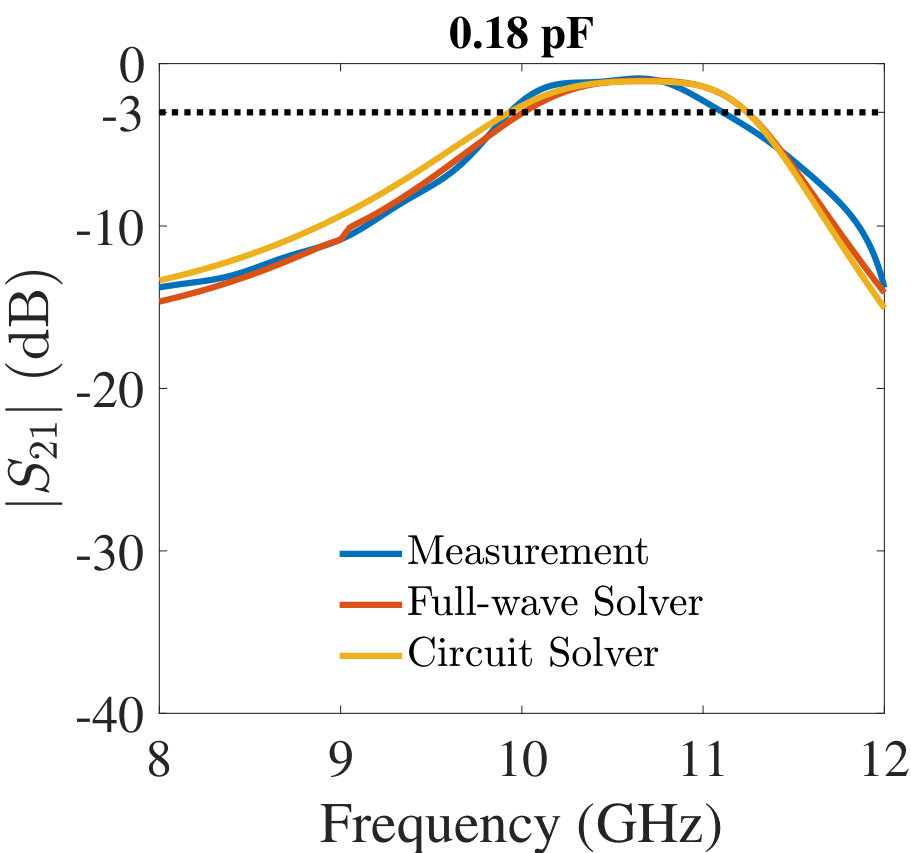 Figure 2
 Figure 3
 Figure 4
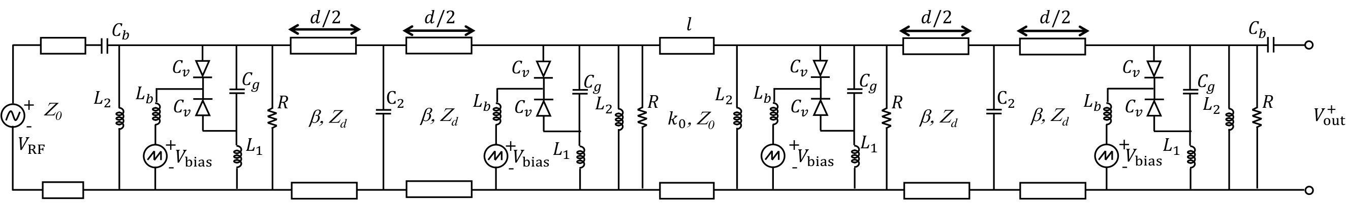 Figure 5
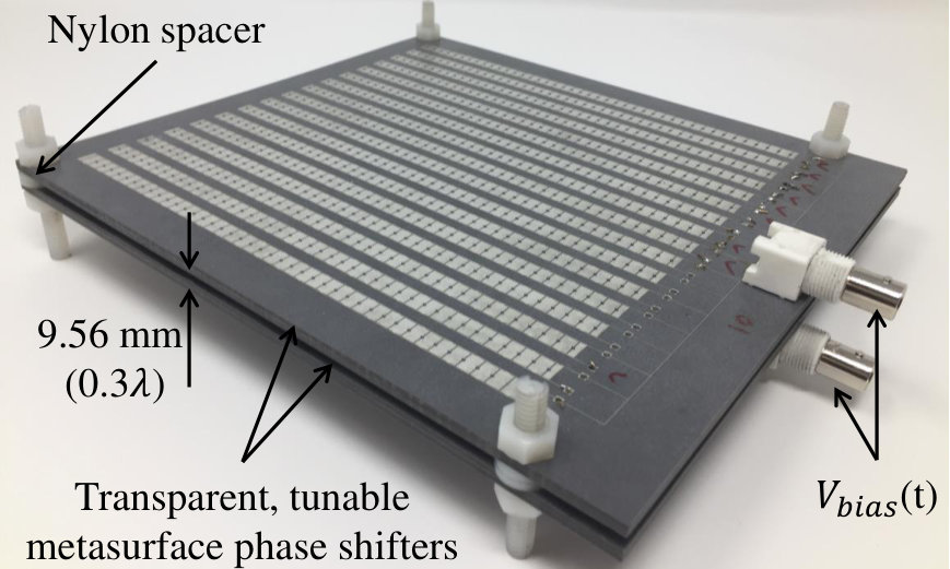 Figure 6
 Figure 7
 Figure 8
 Figure 9
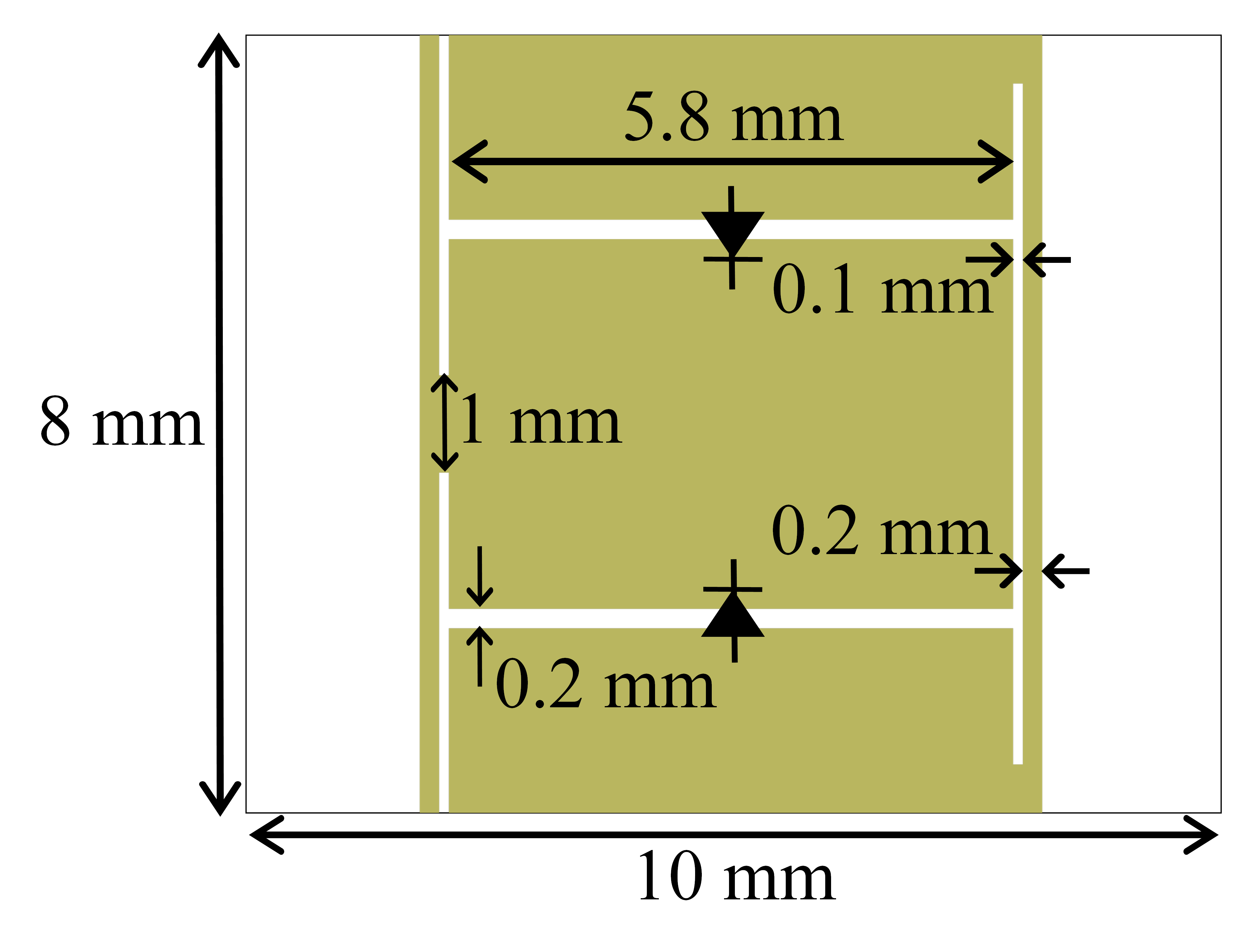 Figure 10
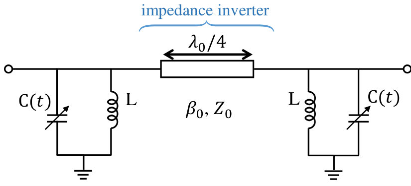 Figure 11
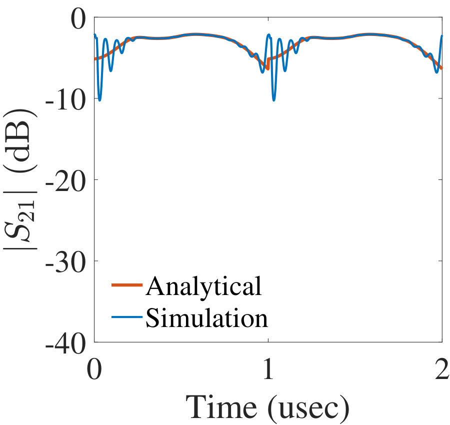 Figure 12
 Figure 13
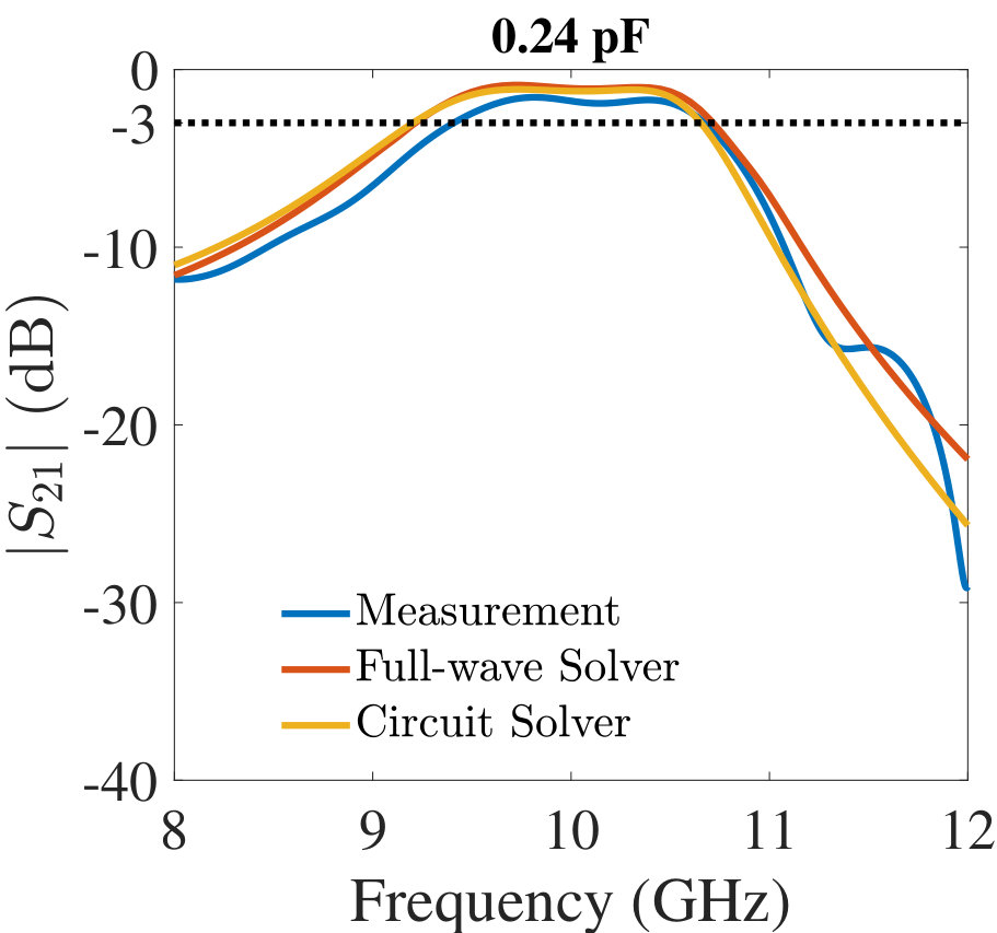 Figure 14
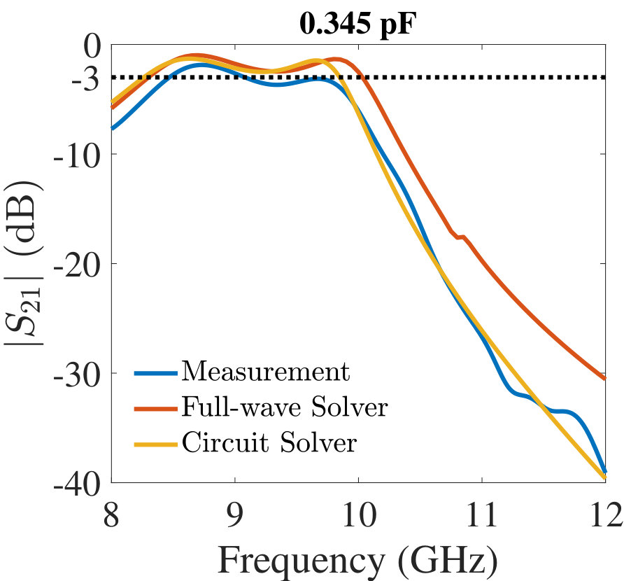 Figure 15
 Figure 16
 Figure 17
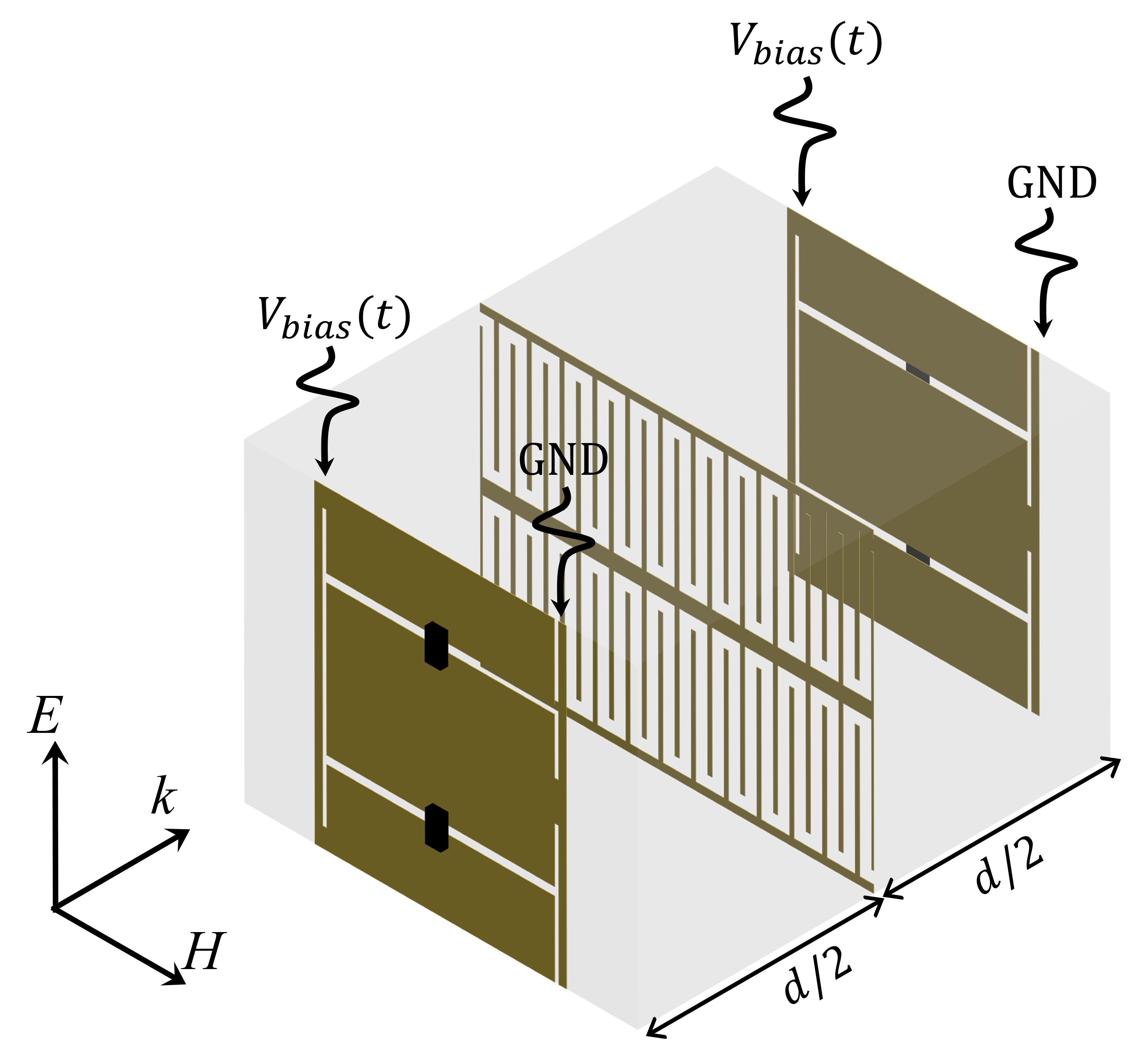 Figure 18
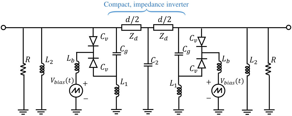 Figure 19
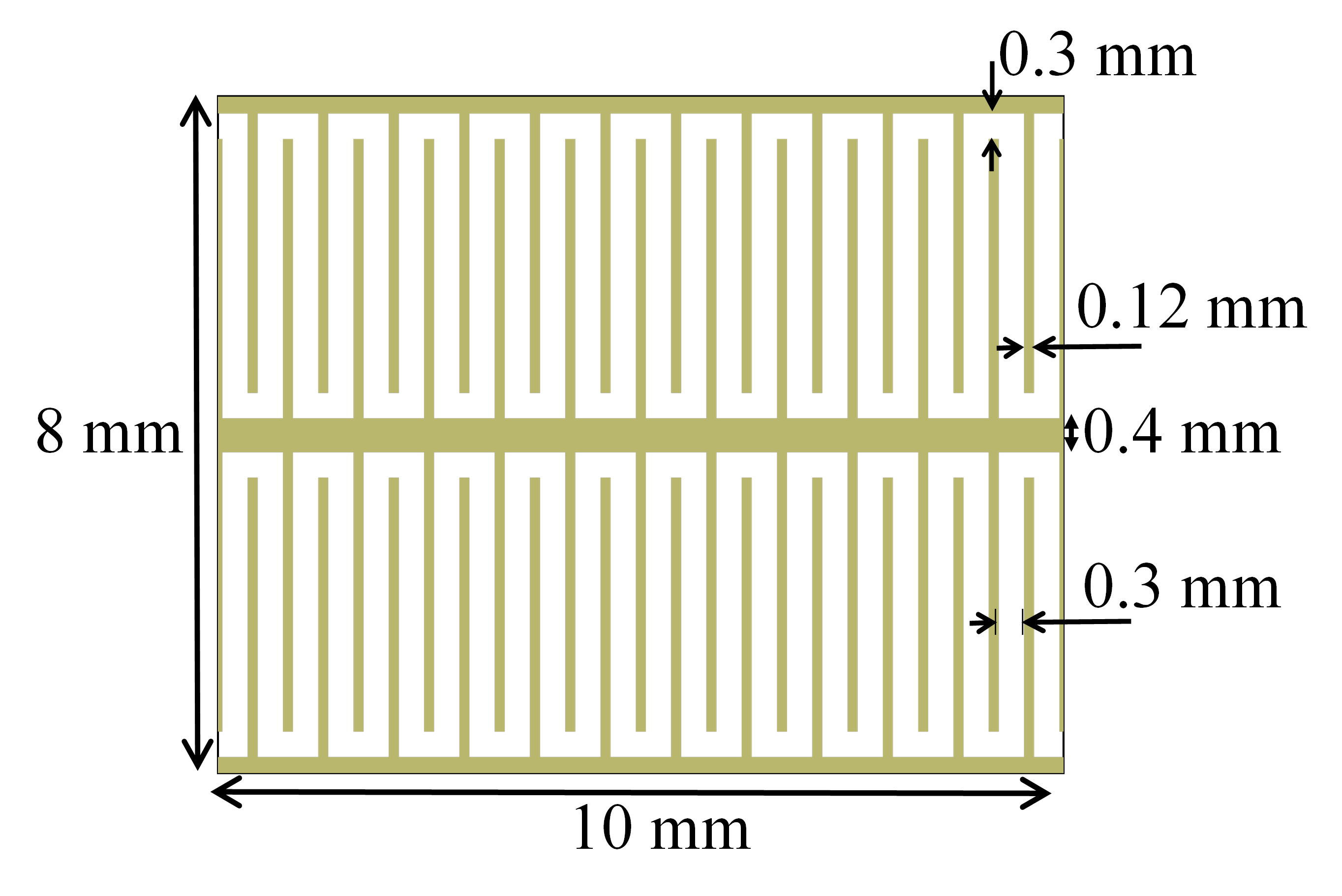 Figure 20
 Figure 21
 Figure 22
 Figure 23
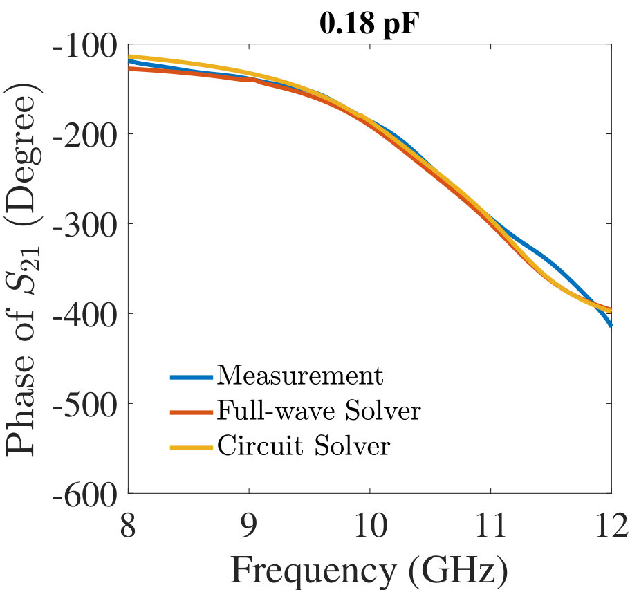 Figure 24
 Figure 25
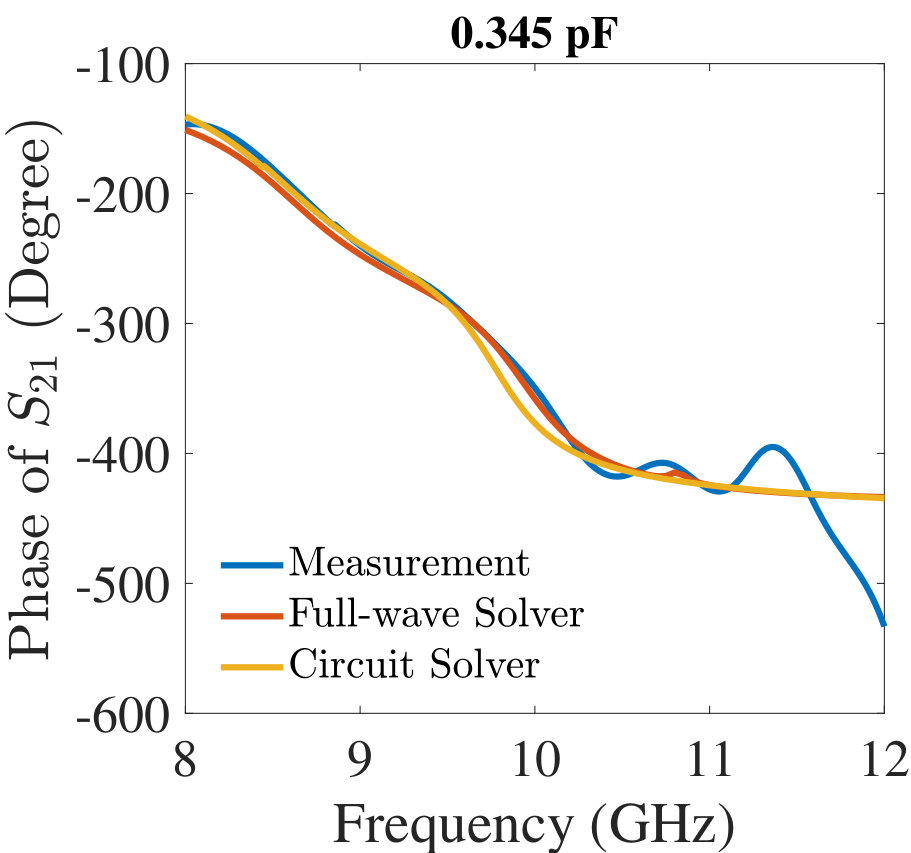 Figure 26
 Figure 27
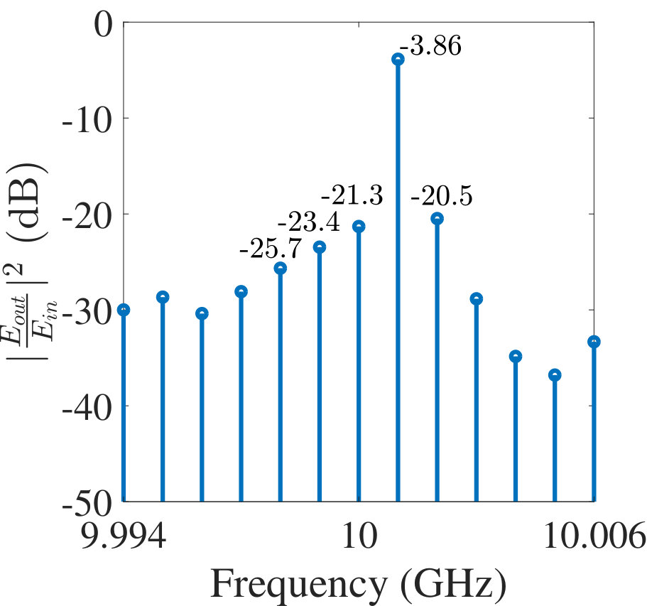 Figure 28
 Figure 29
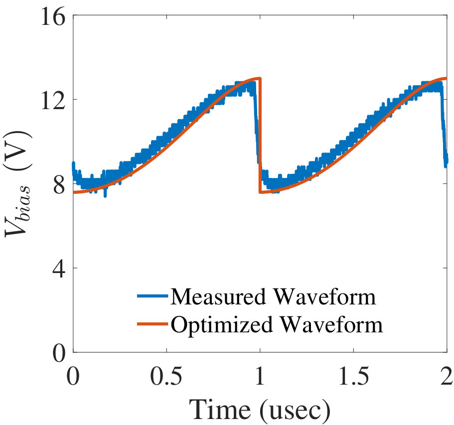 Figure 30
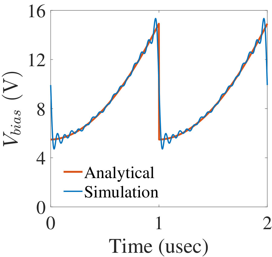 Figure 31
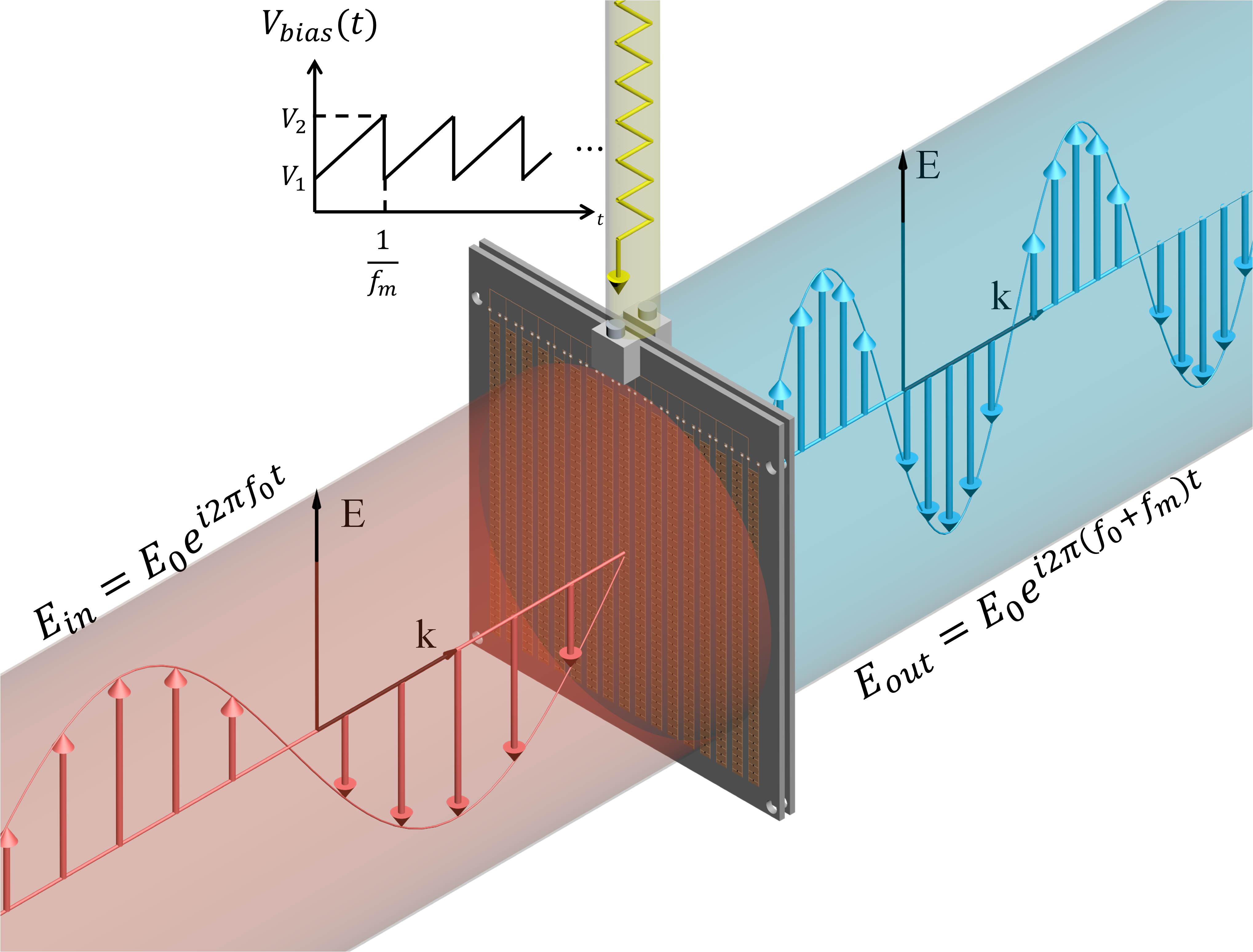 Figure 32
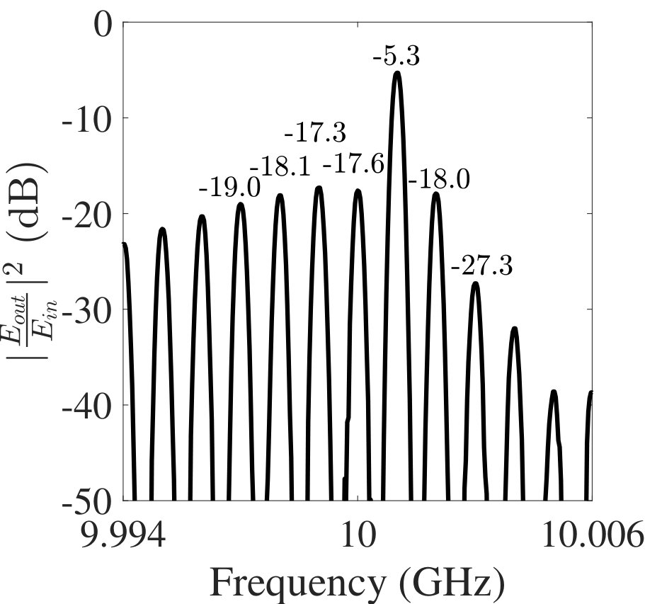 Figure 33
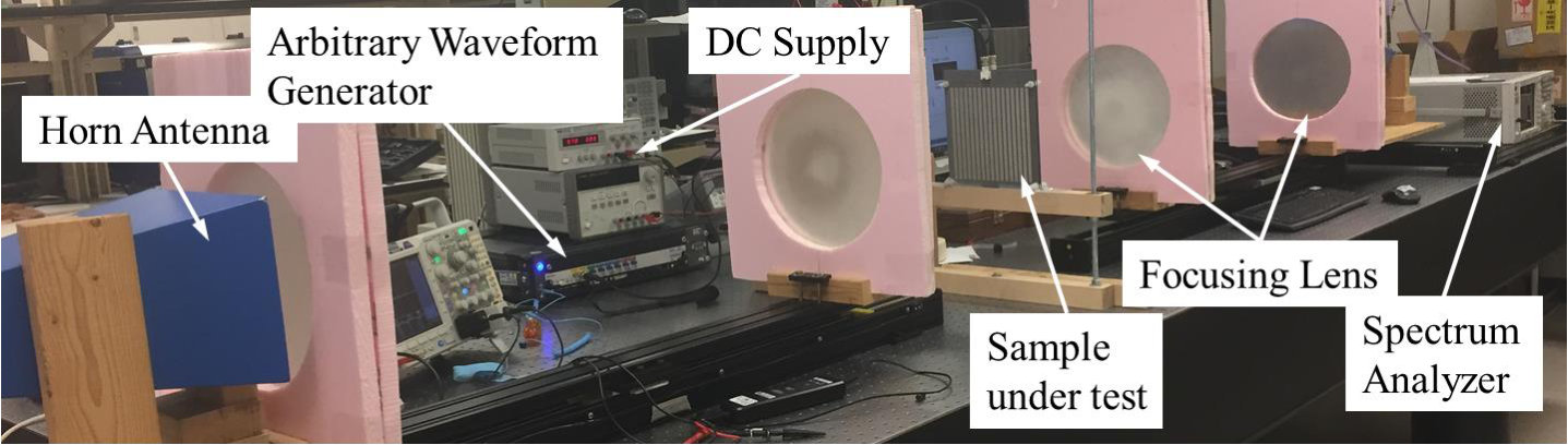 Figure 34
 Figure 35
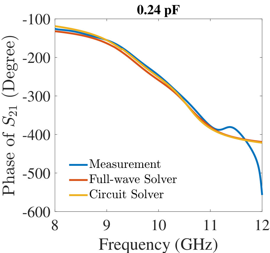 Figure 36
 Figure 37
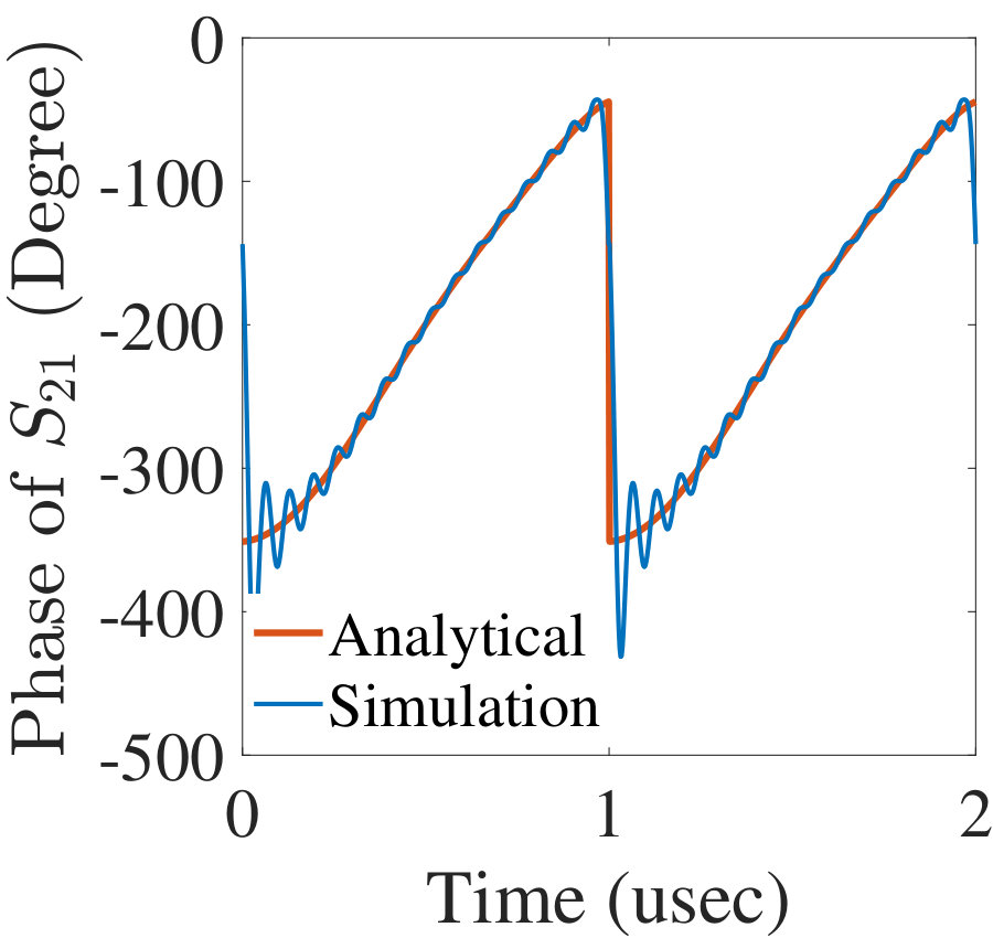 Figure 38
 Figure 39
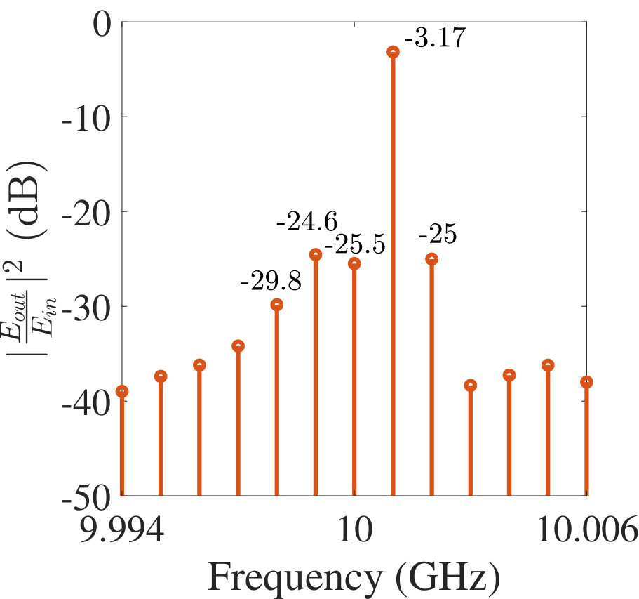 Figure 40
| Symbol | Detailed information and values |
|---|---|
| Extracted free space impedance, | |
| Extracted substrate impedance, | |
| Extracted pattern capacitance, pF | |
| Extracted pattern inductance, nH | |
| Extracted pattern inductance, nH | |
| Extracted pattern capacitance, pF | |
| Extracted pattern resistance, | |
| Varactor diode capacitance | |
| Low frequency block, 100 pF | |
| High frequency block, 100 nH | |
| Substrate thickness, electrical length of | |
| Free-space spacer, electrical length of |
| Bias voltage used in ADS (V) | Varactor capacitance (pF) | Bias voltage used in measurement (V) |
| 4.88 | 0.345 | 7 |
| 5.95 | 0.30 | 8 |
| 7.35 | 0.26 | 9 |
| 8.33 | 0.24 | 10 |
| 9.69 | 0.22 | 11 |
| 11.61 | 0.20 | 12 |
| 14.70 | 0.18 | 13 |
Peer Reviews
No public reviews on file for this paper yet. If you reviewed it on a platform where reviews are public (OpenReview, ICLR, NeurIPS, ICML), you can paste yours below so the community can read it here.
Videos
No videos yet. Explain this paper in a talk, walkthrough, or lecture? Add one.
Serrodyne frequency translation using time-modulated metasurfaces
Zhanni Wu, , Anthony Grbic The authors are with Department of Electrical Engineering and Computer Science, University of Michigan, Ann Arbor, Michigan 48109-2122, USA (e-mail: [email protected]; [email protected]).
Abstract
Temporally modulated metamaterials have attracted significant attention recently due to their non-reciprocal and frequency converting properties. Here, a transparent, time-modulated metasurface that functions as a serrodyne frequency translator, is reported at X-band frequencies. With a simple biasing architecture, the metasurface provides electrically-tunable transmission phase that covers . A sawtooth waveform is used to modulate the metasurface, allowing Doppler-like frequency translation. Two such metasurfaces can be cascaded together to achieve magnetless devices that perform either phase or amplitude non-reciprocity.
Index Terms:
time-modulated metasurfaces, frequency translation
I Introduction
Time-varying metasurfaces, can exhibit dynamically controllable scattering properties, and allow the real-time manipulation of electromagnetic waves. In addition to providing reconfigurable static functionalities, temporal modulation allows harmonic generation and non-reciprocal responses [1, 2]. For example, one can achieve frequency translation, the process of converting an input signal from one frequency to an other, without generating undesired sidebands. In general, there are different ways to achieve frequency translation, including traveling-wave parametric amplifiers [3] and acousto-optic modulation [4, 5]. The serrodyne frequency translator [6, 7], which employs a continuous linear variation of phase (temporal modulation), closely approaches the performance of an ideal frequency translator. Just like a blazed grating (a linear phase gradient in space) converts one spatial frequency to another, the sawtooth phase variation in time (a linear phase gradient in time) converts one temporal frequency to another. In contrast to a sinusoidally driven mixer, a serrodyne frequency translator suppresses the image frequency without added image rejection circuitry. In earlier works, the serrodyne frequency translator has been developed using different phase-tunable devices including ferrite phase shifters [8], electro-optic waveguides [9, 10, 11] and CPW MMIC phase shifters [12].
Here, we present a transparent, time-varying metasurface that achieves free-space, serrodyne frequency translation at X-band frequencies. The metasurface provides full phase variation despite its small physical thickness of mm (). Tunable varactors on the metasurfaces, controlled by a simple biasing network, allow electrically-driven, time-modulated surface properties. The proposed metasurface-based, frequency translators may find a wide range of applications including frequency comb generation [13, 14], arbitrary waveform generation [15], Doppler cloaks [16], modulated antennas [17, 18, 19, 20], radar pulse-shaping [21, 22], and magnetless nonreciprocal devices [23, 24, 25, 26, 27, 28, 29, 30].
II Design and simulation of a transparent, serrodyne frequency translator.
In this section, we propose and describe the corresponding circuit design and metasurface realization for the serrodyne frequency translator. Furthermore, analytical as well as harmonic balance simulation of the transmission spectrum frequency translator are reported.
II-A Circuit design and metasurface realization
Recently [31], we demonstrated a transparent, tunable metasurface that functions as a bandpass phase shifter. The metasurface is impedance-matched to free space and exhibits an electrically-tunable electrical thickness. When modulated with a sawtooth waveform, , with a repetition rate of , the metasurface provides a periodic transmission phase and transmission amplitude . As shown in Fig. 1, for an incident signal of the form , the transmitted signal may be expressed as
[TABLE]
assuming that the modulation frequency is much lower than the signal frequency: . Since the transmission coefficient is periodic in time, the spectrum of the transmitted wave can be written as
[TABLE]
where . Clearly when is unity and is linear with time, the phase shifter functions as an ideal frequency translator:
[TABLE]
The realization of a reflectionless (transparent) metasurface that functions as a phase shifter, with a time-dependent transmission phase, requires control of both its electric and magnetic surface properties. The ratio of electric to magnetic surface susceptibilities must remain constant and equal to the square of the free-space wave impedance, while their product must linearly increase (or decrease) over each modulation period. This can be achieved easily using the simple bandpass filter topology depicted in Fig. 2a. The bandpass filter contains two shunt resonators (LC tank circuits) separated by a phase delay (an impedance inverter). The impedance inverter transforms the second shunt LC resonant circuit to a series LC resonant circuit, allowing both the electric (shunt circuit) and magnetic (series circuit) response to be tuned with variable capacitors [31], controlled by a single bias waveform. The time-dependent capacitors are realized as varactor diodes. The capacitance can be written as,
[TABLE]
The static capacitance is chosen to resonate with the shunt LC tank at an operating frequency of GHz,
[TABLE]
where , is a time-modulated capacitance with a tuning range relatively small compared to . Close to the operating resonant frequency, the image impedance and transmission phase of the phase shifter depicted in Fig. 2a can be calculated as [32]:
[TABLE]
where is the free-space impedance. For capacitance variations , the phase shifter remains impedance-matched to free space: . In addition, the transmission phase of the phase shifter is linearly proportional to the time-varying .
The phase shifter in Fig. 2a can be realized as an electrically tunable metasurface, shown in Fig. 3 [31]. Varactor diodes (MAVR-000120-1411 from MACOM) are integrated on both sides of the metasurface to achieve the required tunability. A miniaturized impedance inverter was designed to replace the spacer and reduce the physical thickness of the metasurface [31]. The extracted circuit model of the designed metasurface is shown in Fig. 2b. In order to achieve of phase variation with low transmission amplitude variation, two metasurfaces were cascaded with a free-space spacer between them of length . A circuit model of the resulting cascaded structure is shown in Fig. 4. The values of the extracted circuit parameters are shown in Table I.
II-B Analytical and harmonic balance simulation results of the transmission spectrum
The circuit was simulated with the commercial circuit solver Keysight Advanced Design System (ADS). The diode was modeled using the spice model of the varactor [33]. Note that the values shown in Table I are cell-averaged values that are scaled by the length-to-width ratio of the unit cell [31]. The circuit model was verified by showing close agreement between simulations of the circuit model depicted in Fig. 2b and full-wave simulations (performed using Ansys HFSS) of the metasurface shown in Fig. 3a for various DC bias voltages (See Fig. 7).
From the DC simulation of the circuit model shown in Fig. 4, the transmission amplitude and phase versus bias voltage relationships (, ) were extracted. An RF bias waveform with a repetition rate of MHz was used to modulate the metasurfaces. Over s modulation period, the bias waveform is modeled as a third-order polynomial with respect to time. Using Eq. 1 and Eq. 2, the transmission spectrum of the frequency translator can be calculated from the extracted and . The coefficients of the third-order polynomial function were optimized to provide the highest frequency translation and lowest sidebands. The optimized sawtooth waveform is shown in Fig. 5a (red line). The corresponding transmission amplitude and phase (, ) are shown in Fig. 5b and Fig. 5c respectively (red lines). The incident frequency was set to GHz. The transmission spectrum calculated using Eq. 1 and Eq. 2 is shown in Fig. 5d. The spectrum clearly shows a Doppler shift to a frequency of GHz. A dB conversion loss and dB sideband suppression is achieved.
A harmonic balance simulation of the circuit model shown in Fig. 4 was performed using Keysight ADS. The incident signal was set to an amplitude of dBm at an operating frequency of GHz. The optimized bias waveform was approximated with 15 harmonics in simulation, as shown in Fig. 5a (blue line). The corresponding simulated transmission amplitude and phase (, ) are shown in Fig. 5b and Fig. 5c respectively (blue lines). The simulated output spectrum is shown in Fig. 5e. A dB conversion loss and dB sideband suppression is achieved in simulation.
III Fabrication and measurement of the transparent, serrodyne frequency translator
Two of the phase shifting metasurfaces were fabricated [31]. A RT/Duroid 5880 substrate ( and ) was used in the design. Nylon spacers with a thickness of mm were used to separate the two metasurfaces, as shown in Fig. 6. The total thickness of the fabricated frequency translator is approximately mm (0.32 ). A total of 5712 MAVR-000120-1411 varactor diodes were integrated in the design. The varactor diodes were controlled simultaneously with a single bias signal. The time-modulated bias signal was connected to the metasurfaces through BNC connectors mounted to each board.
Our measurement results showed that the varactor capacitance versus reverse bias voltage characteristic quoted on the diode data sheet is inaccurate at the operating frequency of 10 GHz [31]. An accurate capacitance vs. reverse bias voltage relationship of the varactors was extracted by comparing transmission measurements at different bias voltages to simulation results for different capacitance values, as shown in Table II. The simulated and measured transmission coefficient entries of the transparent, tunable metasurface phase shifter (given in Fig. 3a) are shown in Fig. 7. For three representative bias voltages 7 V, 10 V and 13 V, the measurement results are given as the blue curves in Fig. 7. The full wave simulation results under the corresponding varactor capacitances (0.345 pF, 0.24 pF and 0.18 pF respectively, as given in Table II) are given as the red curves. In addition, the simulation results of the circuit model of Fig. 2b under the corresponding varactor capacitances are given as the orange curves. Close agreement is observed among measurement, full-wave simulation and circuit simulation results of the phase-shifting metasurface, verifying the parameters given in Table II.
The fabricated frequency translator was measured under a quasi-optical Gaussian beam system, as shown in Fig. 8. A rectangular horn antenna (i.e., Dorado GH-90-25) along with a pair of lenses radiate a Gaussian beam with a beam waist of 114 mm in diameter. The focal lengths of the lenses used are 45 cm. The fabricated frequency translator had a dimension of mm2 [31]. The minimum dimension of the frequency translator is approximately times the beam waist, to limit diffraction. An analog signal generator (Agilent N5183) was used to feed the transmit horn antenna with a dBm signal at 10 GHz. The amplitude of the incident wave impinging on the metasurfaces was measured to be dBm. The receive antenna was connected to a spectrum analyzer (Agilent E4446A). The path loss of the system was measured at the operating frequency and calibrated out of the measurements. The ratio of the calibrated output signal power to input signal power provided the transmission coefficient at each measured frequency harmonic. The bias waveform used in measurement was determined by applying the voltage relationship given in Table II to the optimized bias waveform used in simulation, as shown in Fig. 9a (red curve). The required was provided by a Keysight M8195A arbitrary waveform generator, and amplified with ZHL-3A-S(+) RF amplifiers from Mini-Circuits. The bias waveform across the diode was measured using a differential probe (Tektronix TMDP0200) and Tektronix oscilloscope MDO3024. The measured and simulated bias waveforms are compared in Fig. 9a. The measured transmission spectrum of the fabricated serrodyne frequency translator is shown in Fig. 9b. A dB conversion loss and dB sideband suppression was achieved in experiment. The difference between the measured and simulated transmission spectrum is attributed to the performance of the biasing network. The biasing network was not optimized for a time-varying bias, but originally designed for a DC bias.
IV Conclusion
In conclusion, a transparent serrodyne frequency translator based on time-modulated metasurfaces is reported at X-band frequencies. The fabricated frequency translator achieves dB conversion loss with dB sideband suppression in experiment. The development of time-modulated, phase tunable metasurfaces opens new and exciting areas of research. Specifically, transmissive phase-modulating metasurfaces can be cascaded together, or multiple in tandem, as in [34] and [35], to produce non-reciprocal devices such as broadband isolators and circulators in a compact, low-profile form factor for Gaussian beam (optical and quasi-optical) systems.
Acknowledgment
This work was supported by DSO National Laboratories under Contract No. DSOCO15027, and the Air Force Office of Scientific Research (AFOSR) under Grant No. FA9550-15-1-0101, and the AFOSR MURI program No. FA9550-18-1-0379.
The reference list from the paper itself. Each links out to its DOI / PubMed record.
- 1[1] D. L. Sounas and A. Alù, “Non-reciprocal photonics based on time modulation,” Nature Photonics , vol. 11, no. 12, p. 774, 2017.
- 2[2] C. Caloz, A. Alù, S. Tretyakov, D. Sounas, K. Achouri, and Z.-L. Deck-Léger, “Electromagnetic nonreciprocity,” Physical Review Applied , vol. 10, no. 4, p. 047001, 2018.
- 3[3] H. Zucker, “Traveling-wave parametric amplifier analysis using difference equations,” Proceedings of the IRE , vol. 49, no. 3, pp. 591–598, 1961.
- 4[4] W. Risk, R. Youngquist, G. Kino, and H. J. Shaw, “Acousto-optic frequency shifting in birefringent fiber,” Optics letters , vol. 9, no. 7, pp. 309–311, 1984.
- 5[5] Z. Cheng and C. Tsai, “Baseband integrated acousto-optic frequency shifter,” Applied physics letters , vol. 60, no. 1, pp. 12–14, 1992.
- 6[6] J. S. Jaffe and R. Mackey, “Microwave frequency translator,” IEEE Transactions on Microwave Theory and Techniques , vol. 13, no. 3, pp. 371–378, 1965.
- 7[7] R. C. Cumming, “The serrodyne frequency translator,” Proceedings of the IRE , vol. 45, no. 2, pp. 175–186, 1957.
- 8[8] G. Klein and L. Dubrowsky, “The digilator, a new broadband microwave frequency translator,” IEEE Transactions on Microwave Theory and Techniques , vol. 15, no. 3, pp. 172–179, 1967.