Beamforming with metagratings at microwave frequencies: design procedure and experimental demonstration
Vladislav Popov, Fabrice Boust, Shah Nawaz Burokur

TL;DR
This paper presents a design and experimental validation of microwave metagratings with minimal degrees of freedom for beam steering, demonstrating their effectiveness and analyzing factors influencing their bandwidth.
Contribution
It introduces a detailed design procedure for reflective metagratings with one degree of freedom per diffraction order and provides experimental results validating their performance.
Findings
Successful fabrication of three metagratings demonstrating prescribed diffraction patterns
Experimental results closely match full-wave simulations
Analysis of factors affecting bandwidth and strategies to enhance it
Abstract
As opposed to metasurfaces, metagratings represent themselves sparse arrangements of scatterers. Established rigorous analytical models allow metagratings to overcome performance of metasurfaces in beam steering applications while handling less degrees of freedom. In this work we deal with reflective metagratings that have only as few as one degree of freedom (represented by a reactively loaded thin wire) per each propagating diffraction order. We present a detailed design procedure and fabrication of three experimental samples capable of establishing prescribed diffraction patterns. The samples are experimentally studied in an anechoic chamber dedicated to radar-cross-section bistatic measurements and results are compared with three-dimension full wave numerical simulations. We identify and analyze factors affecting operating frequency range of metagratings, suggest a strategy to…
Click any figure to enlarge with its caption.
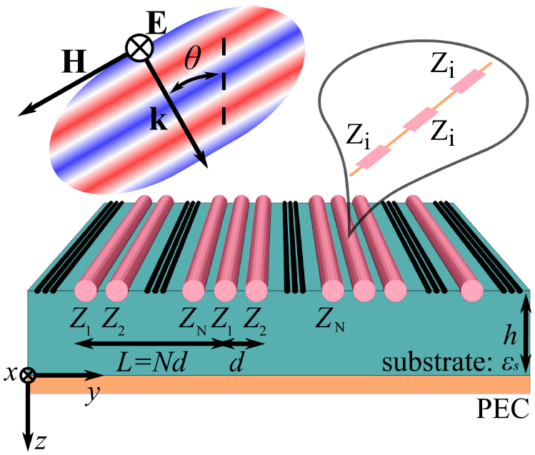 Figure 1
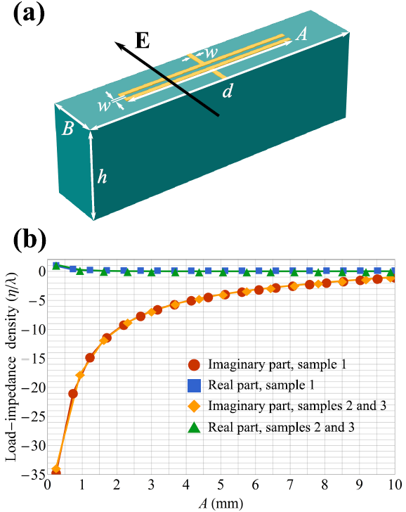 Figure 2
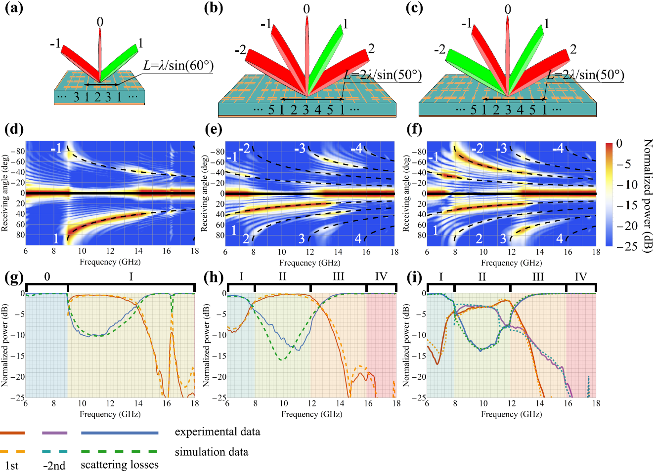 Figure 3
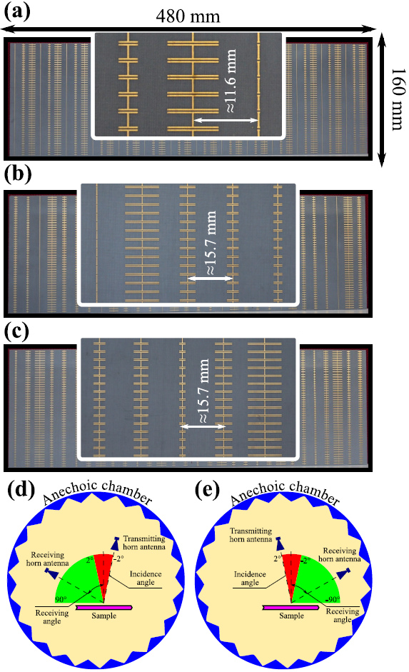 Figure 4
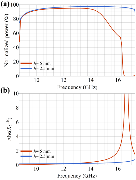 Figure 5
| Loads () | |||||
|---|---|---|---|---|---|
| Sample 1 | - | - | |||
| Sample 2 | |||||
| Sample 3 | |||||
| Arm’s length (mm) | |||||
| Sample 1 | - | - | |||
| Sample 2 | |||||
| Sample 3 |
Peer Reviews
No public reviews on file for this paper yet. If you reviewed it on a platform where reviews are public (OpenReview, ICLR, NeurIPS, ICML), you can paste yours below so the community can read it here.
Videos
No videos yet. Explain this paper in a talk, walkthrough, or lecture? Add one.
Beamforming with metagratings at microwave frequencies: design procedure and experimental demonstration
Vladislav Popov, Fabrice Boust, and Shah Nawaz Burokur © 20XX IEEE. Personal use of this material is permitted. Permission from IEEE must be obtained for all other uses, in any current or future media, including reprinting/republishing this material for advertising or promotional purposes, creating new collective works, for resale or redistribution to servers or lists, or reuse of any copyrighted component of this work in other works.V. Popov is with SONDRA, CentraleSupélec, Université Paris-Saclay, F-91190, Gif-sur-Yvette, France (e-mail: [email protected]).F. Boust is with SONDRA, CentraleSupélec, Université Paris-Saclay, F-91190, Gif-sur-Yvette, France and DEMR, ONERA, Université Paris-Saclay, F-91123, Palaiseau, France (e-mail: [email protected]).S. N. Burokur is with LEME, UPL, Univ Paris Nanterre, F92410, Ville d’Avray, France (e-mail: [email protected]).
Abstract
As opposed to metasurfaces, metagratings represent themselves sparse arrangements of scatterers. Established rigorous analytical models allow metagratings to overcome performance of metasurfaces in beam steering applications while handling less degrees of freedom. In this work we deal with reflective metagratings that have only as few as one degree of freedom (represented by a reactively loaded thin wire) per each propagating diffraction order. We present a detailed design procedure and fabrication of three experimental samples capable of establishing prescribed diffraction patterns. The samples are experimentally studied in an anechoic chamber dedicated to radar-cross-section bistatic measurements and results are compared with three-dimension full wave numerical simulations. We identify and analyze factors affecting operating frequency range of metagratings, suggest a strategy to increase the bandwidth.
Index Terms:
Electromagnetic metasurfaces, diffraction, metagratings, beam steering, reflector antennas.
I Introduction
A diffraction grating, defined as a periodic optical structure with infinite extent in one direction diffracts waves incident on its surface [1]. Being imposed by the periodicity of a grating, which can be of the order of a free-space wavelength or greater, an incident wave is scattered as propagating diffraction orders only in certain directions. Concerning their applications, diffraction gratings have been widely used in laser resonators to tune and narrow lasing bandwidth [2, 3]. Blazed or echelette gratings [4, 5, 6] capable of scattering an incident wave into a specific diffraction order have been applied in frequency-scanning reflector antennas [7, 8, 9, 10] and for radar cross section (RCS) reduction [11, 12] at microwave frequencies and in Littrow mount external cavity lasers in optics [13]. Classical blazed gratings are three-dimensional (3D) structures that generally take the form of right-angle sawtooths [14] and rectangular grooves [5].
In the last few years, 2D metamaterials, also known as metasurfaces [15], have been applied to mimic blazed gratings functionality [16]. Metasurfaces representing themselves as very thin structures have been proposed as planar alternatives to metamaterials to exhibit light manipulation possibilities in various frequency domains, extending from microwave to visible frequencies. Local magnitude and phase of reflection and/or transmission coefficients of a metasurface can be controlled, and can thus be used to manipulate scattered wavefront of an incident beam. As such, metasurfaces have been used to perform functions including anomalous reflection and refraction [17, 18, 19, 20, 21, 22], deflection [23, 24, 25, 26], lensing [23, 24, 27, 28, 29, 30], thin-film cloaking [31, 32, 33], coupling of propagating waves to surface waves [34, 35], optical vortex beams generation [36, 37, 38, 39], and holographic imaging [40, 41, 42, 43, 44, 45], to name a few.
Most of the metasurface-based wavefront manipulation geometries rely on the generalized laws of reflection and refraction presented in Ref. [17]. However several studies have shown that this approach suffer from low efficiency, particularly in configurations where extreme wave manipulation is considered (see, e.g., Refs. [46, 47, 48]). Moreover, implementation of field transformations into physical metasurface structures can reveal to be highly challenging and drawbacks concerning optimization time, design complexity of subwavelength periodically arranged resonant meta-atoms and material losses still exist.
Very recently, the concept of metagratings evolved from classical diffraction gratings has been proposed as an interesting alternative to metasurfaces for boosting wavefront manipulation efficiency [49]. They are designed for diffraction engineering by cancelling a finite number of undesired propagating diffraction orders and allowing desired ones to radiate. In general, a metagrating is an array of scatterers (polarizable particles) separated by a distance of the order of the operating wavelength . The sparse arrangement of scatterers does not allow one describing metagratings in terms of local reflection and transmission coefficients (or surface impedances) as metasurfaces. In terms of meta-atoms, a metagrating consists of a limited number of meta-atoms in a supercell (period) compared to a metasurface which is composed of supercells incorporating numerous meta-atoms with subwavelength periodicity. Although metagratings can be considered as relatively simple systems in comparison to metasurfaces, functionalities such as perfect anomalous reflection and perfect beam splitting have been demonstrated in Refs. [49, 50, 51, 52], where three propagating diffraction orders were considered at most and were handled by only two degrees of freedom. In Refs. [53, 54], the concept was generalized and the possibility to fully control an arbitrary number of propagating diffraction orders by means of a specific number of degrees of freedom was demonstrated.
Essentially metagratings can be understood by considering an example of 1D metagratings represented by a periodic array of supercells composed of thin wires each. An incident wave excites polarization line currents in the wires resulting in the scattered field represented by Floquet-Bloch modes which are defined by the period of the array (i.e., the length of the supercell). In particular, the diffraction angles of the propagating diffraction orders can be found via the grating formula: , where represents the number of an order and is the incidence angle of an impinging plane wave. Furthermore, a line current is mathematically represented by the 2D Dirac delta function that allows one to find the scattered field analytically, i.e., to know the complex amplitudes of all diffraction orders (propagating and nonpropagating).
In what follows, we deal with a particular configuration of 1D metagratings when thin wires are placed on the top of a metal-backed dielectric substrate as illustrated in Fig. 1. A plane-wave illumination is assumed and the wires interact only with the TE-polarized field. As it was shown in the theoretical study [53], the complex amplitudes of the electric field of the reflected plane waves are given by the following expression:
[TABLE]
where and are respectively, the wavenumber and the characteristic impedance outside the substrate, and represent respectively, the tangential and normal components of wavevector of the plane waves, and is the corresponding Fresnel’s reflection coefficient. Equation (1) suggests that complex amplitudes of all propagating diffraction orders can be set arbitrarily if there are at least line currents in a supercell. Other parameters of the system, such as the parameters of the substrate and the distances between the line currents are assumed being fixed conversely to previously mentioned studies in Refs. [49, 50, 51, 52].
Although here we focus on the TE polarization and reflective configuration of metagratings, the case of TM polarization can be studied similarly by means of duality relations (see, e.g., Refs. [55, 56]). The mathematical approach used in [53] to derive Eq. (1) can be straightforwardly generalized on transmissive-type metagratings, as the particular configuration studied in [57].
In this work, based on the theoretical study of Ref. [53], the design of simplified metagratings composed of the number of loaded wire as the considered number of propagating diffraction orders, is presented. The load-impedance densities of the wires are calculated and engineered from subwavelength wire elements. Measurements are performed on fabricated samples to experimentally validate the theoretical results . The rest of the paper is organized as follows. In Section II we provide the design methodology of the reflective-type metagratings. Section III is devoted to the discussion of the experimental results and their comparison to simulation results. In the same Section we discuss the mechanism behind the observed wide-band response of the proposed metagratings (see also Refs. [51, 53]). Section IV concludes the paper.
II design procedure
In order to be able to control the diffraction pattern with a metagrating one has to carefully engineer it. An appropriate dielectric substrate for a given frequency range is required. Its thickness and relative permittivity should be carefully chosen in order to avoid excitation of waveguide modes [53]. These waveguide modes are analog of surface plasmon polaritons responsible for well-known grating anomalies (or Wood’s anomalies). On the other hand, the presence of waveguide modes leads to divergence of certain Fresnel’s reflection coefficients in Eq. (1), manifesting themselves in significant numerical errors. Thus, in order to select a good substrate for a given metagrating’s period , one can plot the absolute value of the first few Fresnel’s reflection coefficients corresponding to nonpropogating diffraction orders as a function of the substrate’s parameters (thickness and permittivity) and avoid poles. As a rule of thumb, a substrate with low permittivity and thickness of the order of is a good candidate for the design of metagratings.
After selecting the correct substrate, the calculation of the characteristics of scatterers composing the metagrating has to be performed. Incident plane wave excites polarization line currents in loaded thin wires that can be characterized by load-impedance and input-impedance densities. Each configuration of the diffraction pattern requires different set of load-impedance densities found from the Ohm’s law:
[TABLE]
The right-hand side of Eq. (2) represents the total electric field at the location of the wire (including the self-action ). Thus, is the external electric field created by the incident wave reflected from the substrate and the sum takes into consideration the mutual interactions of the wire with the rest of the wires (infinite number) and the grounded substrate. The quantities are called as mutual-impedance densities. Generally, load-impedance densities calculated from Eq. (2) require engineering active and/or lossy response, i.e. . For instance, in order to perform a large angle nonspecular reflection by means of a metagrating, one has to cancel two propagating diffraction orders out of available (as in the case of normal incidence). Then, the conditions and leave one with only a single variable (being the phase of ) that cannot be used to satisfy three different equations
[TABLE]
providing reactive load-impedance densities (the asterisk stands for the complex conjugate). Equation (1) relates the complex amplitudes and currents, i.e. Eq. (3) can be rewritten in terms of , with numbering propagating diffraction orders.
In order to deal with passive and lossless metagratings, equation (3) has to be satisfied. To that end, spurious scattering in undesired propagating diffraction orders has to be permitted. By introducing scattering losses, we sacrifice the efficiency for sake of design that would require only reactive elements. An optimal configuration is achieved by numerically maximizing the power scattered in desired propagating diffraction orders while minimizing the left-hand-side of Eq. (3). It is worth to note that reflecting metasurfaces face the same difficulty (see for e.g., Refs. [46, 47]) with notable exception of Refs. [58, 59], which are rather special cases. Generally, the efficiency of nonspecular reflection is used to evaluate the performance of conventional reflectarrays, i.e., efficiency decreases when the angle of nonspecular reflection increases. However, highly efficient multichannel reflection can still be achieved as we demonstrate further.
Once Eq. (3) is satisfied and corresponding complex amplitudes are found, load-impedance densities are calculated from Eq. (2) and implemented by wire elements engineered at subwavelength scale. Although in a general case both capacitive and inductive loads might be required [54], only capacitive elements are necessary in the examples considered further for an operating frequency set to GHz. It is assumed that the samples would be fabricated by means of the conventional printed-circuit-board (PCB) technology. Thus, thin wires are represented by metallic strips of width , thickness of m, and input-impedance density as given in Ref. [60]. Capacitive loads are obtained by means of a microstrip printed capacitances, as illustrated in Fig. 2 (a). Load-impedance density of printed capacitances can be approximated analytically using formulas for sheet impedance of a patch array [61] as it is done in [50, 53, 51, 54]. Although the analytical model represents a simple tool for designing metagratings, it takes into account the mutual coupling with adjacent loaded wires via a phenomenological scaling parameter which is found by means of 3D full-wave simulations of an entire supercell and, thus, is not unique. On the other hand, a recently developed simulation-based approach [56] allows one to construct metagrating unit cell by unit cell. Instead of performing computations on a whole supercell, it deals with a single unit cell and takes analytically into account the interaction between adjacent wires to retrieve load-impedance density. Additionally, simulation-based approaches are advantageous for being able to consider all practical aspects of meta-atoms, such as finite thickness of the metal cladding and conduction and dielectric losses.
We design three experimental samples of metagratings to operate at GHz ( mm) and we assume a normally incident plane-wave illumination () for all three configurations. The functionalities of these three samples are schematically illustrated in Figs. 3 (a)–(c). The mm thick F4BM220 dielectric substrate having permittivity is selected as a good candidate for the proposed designs. The first sample deals with three diffraction orders maximizing the power scattered in the order and suppressing scattering in the the and orders. Hence, it is composed of three unit cells per supercell, which has a length at GHz. This metagrating is able to achieve anomalous reflection at degrees. The second and third samples each has five unit cells per supercell of length , which allows one to control five diffraction orders: , , , and . The second sample maximizes the power scattered in the propagating diffraction order and thus performs small angle anomalous reflection, corresponding approximately to at GHz. The third sample equally excites the and orders while suppressing the three others.
On the basis of these specifications, the required load-impedance density are calculated by means of Eqs. (1) – (3) and are presented in Table I. Only two capacitive unit cells of length and need to be simulated for the design of the three metagratings. A schematics of the unit cell is shown in Fig. 2 (a). In 3D full-wave simulations performed with COMSOL MULTIPHYSICS, periodic boundary conditions are applied to the side faces of the unit cell and the model is excited with a periodic port. Parameters and are fixed to mm and mm, respectively. The arm’s length of the printed capacitance is used as a tuning parameter for the load-impedance density. The load-impedance densities are first extracted from the parameter of the unit cell as detailed by the procedure in [56] and are plotted as function of in Fig. 2 (b). Although being built for two different parameters , the two curves in Fig. 2(b) almost coincide. It proofs that the analytical model used in Ref. [56] to take into account the interaction between adjacent wires and the substrate, allows one to obtain the load-impedance density of a wire itself and not of a corresponding array. Eventually, the load-impedance densities are used to tailor the geometrical parameters of the microstrip printed capacitances listed in Table I. Photographies of the fabricated samples are displayed in Fig. 4 (a)–(c) and their physical size is approximately mm (-direction) by mm (-direction).
III Experimental results
In this section we demonstrate experimentally the control of diffraction patterns with the proposed and fabricated metagrating designs. The samples are tested in an anechoic chamber dedicated to radar-cross-section bistatic measurements, where transmitting and receiving horn antennas are mounted on a circular track of m radius. A schematic representation of the experimental setup is shown in Figs. 4 (d) and (e). In the current experiments, the transmitter is fixed and the receiver moves with step and the minimum angle between the transmitter and receiver for the scanning is . In order to be able to measure the specular reflection, the transmitter is fixed at . Thus, the experiments are conducted in two steps: when the transmitter is fixed at , the receiver moves form to , as it is clearly illustrated in Figs. 4 (d) and (e).
Figures 3(d)–(f) visualize angle measurements of the scattered power in the frequency range spanning from to GHz. It is clearly observed that the positions of the main lobes (corresponding to diffraction orders) are in perfect agreement with the results given by the grating formula (represented by black dashed curves). Here, is the speed of light in vacuum and is the frequency. However, the spectrum of waves scattered from a finite-size sample in the far-field is much more complex than just a few plane waves representing propagating diffraction orders. Thus, in order to estimate the performance of the samples we execute next steps following Ref. [52]. In the first place, we localize each diffraction order between the angles and which correspond to dB of the power attenuation with respect to the maximum power of the lobe. The maximum is found near the angle . Finally, the normalized power scattered in a given diffraction order at the frequency is estimated by means of the following integral formula
[TABLE]
where is the absolute power scattered in the receiving angle at the frequency . The summation in the denominator is performed over all propagating diffraction orders at the frequency . Figures 3(g)–(i) show the performance of the experimental samples (solid curves obtained by means of Eq. (4)) as function of the frequency, scattering losses represent the power scattered in undesired diffraction orders. The dashed curves demonstrate the results obtained from 3D full-wave simulations (a supercell with imposed periodic boundary conditions and excited by a periodic port). By comparing the solid and dashed curves, one can observe a good agreement between the experimental and simulation results.
Although the samples were designed to operate at a single frequency ( GHz), it is seen that the scattering losses remain low in a wide range of frequencies. One of the most important factors affecting an operating frequency range is the frequency response of unit cells. Resonant elements, in a general manner, significantly decrease an operating frequency range (see, e.g., Refs. [54, 56]). As demonstrated by Fig. 2(b), unit cells used to construct experimental samples do not exhibit resonances at GHz. Since the designed metagratings possess a number of degrees of freedom equal to the number of propagating diffraction orders, it is expected that the scattering losses increase when approaching frequencies where the number of propagating diffraction orders changes (corresponding to different areas in Figs. 3(g)–(i) labeled with roman digits). While it is the case for the second and third samples, the performance of the first one decreases far before the appearance of the second propagating diffraction orders, see Figs. 3(g)–(i). It unveils yet another crucial factor influencing an operating frequency range: excitation of waveguide modes discussed in the very beginning of Section II. Although we avoid waveguide modes around the design frequency of GHz, they may appear at lower or higher frequencies and this is exactly what happens with the first sample, as we further present in Fig. 5. A waveguide mode is excited at the frequency when the Fresnel’s reflection coefficient diverges and leads to drastic decrease of the performance of the metagrating, as it can be clearly observed in Fig. 5 when comparing two different thicknesses of the dielectric substrate. In the experimental and simulation data the waveguide mode manifests itself in the resonance observed around GHz, see Figs. 3(d) and (g). Figure 5(a) presents the computational results of maximizing the power of a normally incident plane wave coupled to the propagating diffraction order in the three unit cells per period metagrating, assuming purely reactive load-impedance densities. As demonstrated, the excitation of the waveguide mode can be suppressed by choosing a thinner substrate (for e.g. mm instead of mm) which enables restoring the performance over the entire range of frequencies where there are three propagating diffraction orders (see blue curves in Fig. 5).
IV conclusion
To conclude, we have described in details the design procedure of reflective metagratings and tested three experimental samples able of establishing prescribed diffraction pattern in a wide frequency range. The experimental results have demonstrated a good agreement with 3D full-wave simulations. Thus, we have experimentally verified the concept of metagratings for controlling multiple beams with as few as one degree of freedom (represented by a reactive load) per a propagating diffraction order. We have identified the main factors affecting the operating frequency range of metagratings which should facilitate the development of wide-band beamforming devices in the future.
acknowledgements
The authors acknowledge the help of Anil Cheraly (ONERA) in conducting the experiments.
The reference list from the paper itself. Each links out to its DOI / PubMed record.
- 1[1] M. Born, E. Wolf, A. B. Bhatia, P. C. Clemmow, D. Gabor, A. R. Stokes, A. M. Taylor, P. A. Wayman, and W. L. Wilcock, Principles of Optics: Electromagnetic Theory of Propagation, Interference and Diffraction of Light , 7th ed. Cambridge University Press, 1999, ch. Elements of the theory of diffraction, pp. 412 –– 516.
- 2[2] F. P. Schäfer, Dye Lasers , 3rd ed. Springer-Verlag Berlin Heidelberg, 1990.
- 3[3] F. Duarte and L. W. Hillman, Dye Laser Principles . San Diego: Academic Press, 1990, ch. Narrow-linewidth pulsed dye laser oscillators, pp. 133 – 183.
- 4[4] E. V. Jull, J. W. Heath, and G. R. Ebbeson, “Gratings that diffract all incident energy,” J. Opt. Soc. Am. , vol. 67, no. 4, pp. 557–559, Apr 1977.
- 5[5] A. Hessel, J. Schmoys, and D. Y. Tseng, “Bragg-angle blazing of diffraction gratings,” J. Opt. Soc. Am. , vol. 65, no. 4, pp. 380–384, Apr 1975.
- 6[6] E. V. Jull, N. C. Beaulieu, and D. C. W. Hui, “Perfectly blazed triangular groove reflection gratings,” J. Opt. Soc. Am. A , vol. 1, no. 2, pp. 180–182, Feb 1984.
- 7[7] J. Shmoys and A. Hessel, “Analysis and design of frequency scanned transmission gratings,” Radio Science , vol. 18, no. 04, pp. 513–518, July 1983.
- 8[8] F. S. Johansson, “A new planar grating-reflector antenna,” IEEE Transactions on Antennas and Propagation , vol. 38, no. 9, pp. 1491–1495, Sep. 1990.