A New Cyber-Secure Countermeasure for LTI systems under DoS attacks
Nilanjan Roy Chowdhury, Nandini Negi, Aranya Chakrabortty

TL;DR
This paper introduces a cyber-secure control strategy for LTI systems under DoS attacks, combining sparse LQR design, message rerouting, and structured H2 control to maintain system stability and performance.
Contribution
It proposes a novel countermeasure integrating message rerouting and structured H2 control to enhance cyber-security in LTI systems against DoS attacks.
Findings
The rerouting strategy effectively mitigates the impact of link attacks.
Structured H2 control maintains optimal feedback gains post-attack.
Simulations demonstrate improved system resilience under cyber-attacks.
Abstract
This paper presents a new counter-measure to mitigate denial-of-service cyber-attacks in linear time-invariant (LTI) systems. We first design a sparse linear quadratic regulator (LQR) optimal controller for a given LTI plant and evaluate the priority of the feedback communication links in terms of the loss of closed-loop performance when the corresponding block of the feedback gain matrix is removed. An attacker may know about this priority ordering, and thereby attack the links with the highest priority. To prevent this, we present a message rerouting strategy by which the states that are scheduled to be transmitted through the high priority links can be rerouted through lower priority ones in case the former get attacked. Since the attacked link is not available for service, and the states of the low priority links can no longer be accommodated either, we run a structured…
Click any figure to enlarge with its caption.
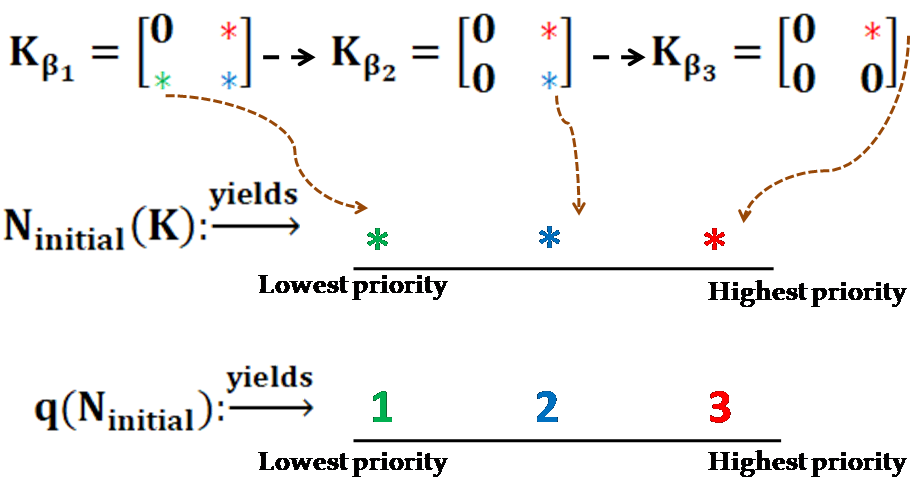 Figure 1
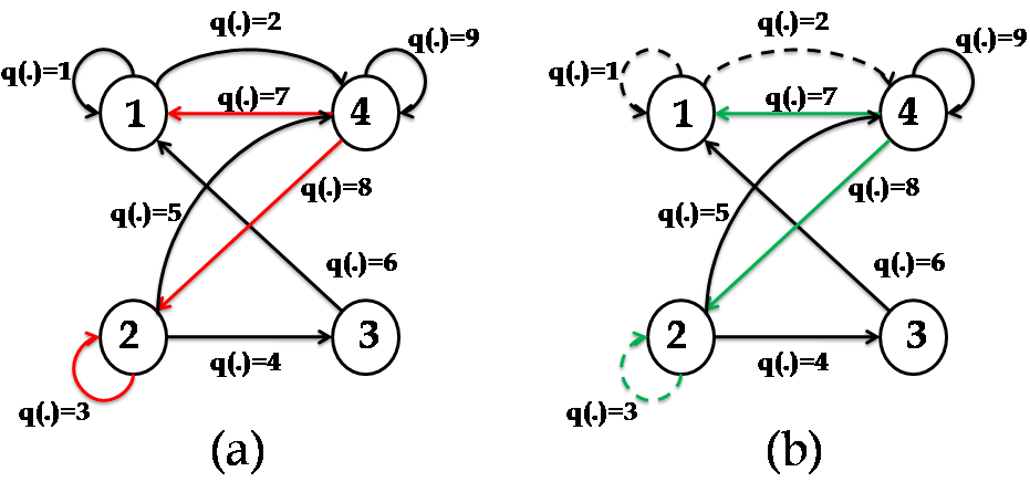 Figure 2
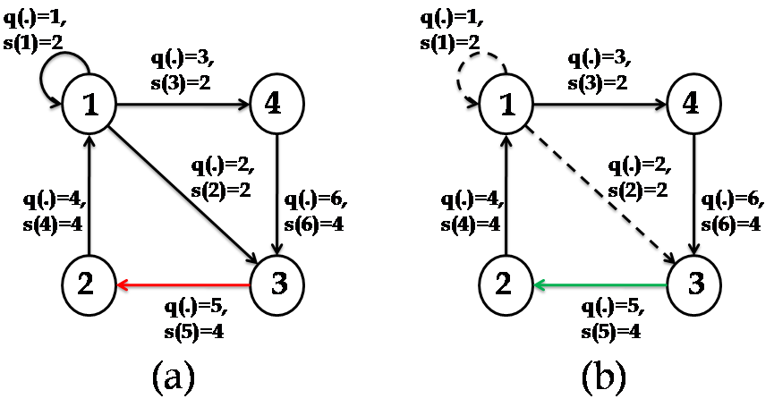 Figure 3
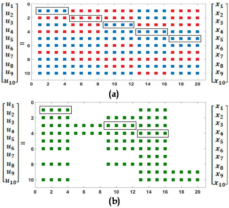 Figure 4
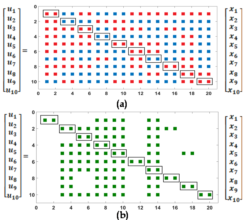 Figure 5
Peer Reviews
No public reviews on file for this paper yet. If you reviewed it on a platform where reviews are public (OpenReview, ICLR, NeurIPS, ICML), you can paste yours below so the community can read it here.
Videos
No videos yet. Explain this paper in a talk, walkthrough, or lecture? Add one.
A New Cyber-Secure Countermeasure for LTI systems under DoS attacks
Nilanjan Roy Chowdhury, Nandini Negi, Aranya Chakrabortty
Department of Electrical and Computer Engineering, North Carolina State University, USA
Email: [email protected], [email protected], [email protected]
Abstract
This paper presents a new counter-measure to mitigate denial-of-service cyber-attacks in linear time-invariant (LTI) systems. We first design a sparse linear quadratic regulator (LQR) optimal controller for a given LTI plant and evaluate the priority of the feedback communication links in terms of the loss of closed-loop performance when the corresponding block of the feedback gain matrix is removed. An attacker may know about this priority ordering, and thereby attack the links with the highest priority. To prevent this, we present a message rerouting strategy by which the states that are scheduled to be transmitted through the high priority links can be rerouted through lower priority ones in case the former get attacked. Since the attacked link is not available for service, and the states of the low priority links can no longer be accommodated either, we run a structured control algorithm to determine the post-attack optimal feedback gains. We illustrate various aspects of the proposed algorithms by simulations.
I Introduction
Security of cyber-physical systems has drawn a significant research attention in recent times. Due to notable instances of cyber-attacks such as WannaCry [1], NotPetya [2], and Ukranian blackout [3], there have been increased interests to design countermeasures to mitigate attacks for cyber-physical systems. A significant part of the existing work focuses on centralized systems (see e.g., [4], [5]) while the recent results in [6], [7] rely on distributed algorithms. Prompted by these considerations, this paper presents a novel sparse optimization based countermeasure to alleviate cyber-attacks for a general class of LTI systems.
System theoretic approaches to tackle a class of cyber-attacks namely Denial of Service (DoS in short) have recently been investigated in [8, 9, 10]. Given a LTI system, [8] presents a novel analysis methodology to maintain the closed loop stability under DoS attacks, while [9] unveils a similar analysis for its nonlinear counterpart. Given a class of complex networks, [10] analyzes the consensus property of self-triggered agents in the presence of DoS attacks. The analysis documented in [10] introduces the notion of persistence-of-communication and characterizes DoS frequency and duration to attain consensus under DoS attacks.
Substantial studies have been undertaken on the analysis of consensus/ synchronization behavior under DoS attacks, see, for example [11, 12, 13] and the references therein. In the context of multi-agent systems, a group of agents is said to reach consensus/ synchronization when all individuals converge towards a common value (consensus) / state (synchronization). Consensus analysis over unreliable networks has been motivated by the seminal contribution from [11], in which, the authors consider a linear consensus model in the presence of misbehaving agents whose behavior diverge from the nominal consensus evolution. Given a complex network having misbehaving agents, [11] illustrates the problem of ensuring consensus under non-colluding and Byzantine attacks. Given a class of general LTI systems, consensus under DoS attacks is analyzed for undirected [12] and directed [13] topology. The results in [12, 13] hypothesize sufficient conditions to ensure asymptotic consensus and also characterize the frequency and the duration of the DoS interval. However, the above analysis primarily relies on static graphs illustrating an idealistic setup.
Recently game-theoretic results are employed in conjunction with distributed optimization to tackle the security problems for large-scale cyber-physical networks. In the game-theoretic setup, the notion of interdependent security games has recently been explored to compute optimal and strategic security investments by multiple defenders, for example see [14, 15]. In [14, 15], the authors consider each defender is responsible for the security of multiple assets, in which the inter-dependencies among the assets captured by an interdependency graph. The authors redesign the problem of computing the optimal defense allocation by a single defender as a convex optimization problem and establish the existence of a pure Nash equilibrium of the game between multiple defenders. Given a networked control system, [16] investigates a slightly different problem, where the authors reformulate a general-sum, two-player, mixed strategy game between an attacker and a defender. The authors of [16] exploit the nonlinear programming paradigm to analyze the dependence of a Mixed Strategy Nash Equilibrium on the relative budgets of the players and preserve important network nodes to attain a desirable LQR performance.
Summary of Contributions: In light of the aforementioned works, in this paper we present a new appoach for mitigating DoS attacks by using ideas from sparse optimal control. Given a LTI system defined over a network of nodes, we first design a sparse linear quadratic regulator (LQR) optimal controller using -sparsity promotion techniques, proposed in [17]. The LQR control law is given as . The non-zero blocks of the sparse matrix indicate the existence of communication links between nodes and , carrying state to controller . We carry out an offline analysis to evaluate the priority of these feedback communication links in terms of how much loss is incurred in the closed-loop LQR objective function when any block is removed. We assume that an attacker may also know about this priority ordering, and thereby is most likely to attack the links with highest priority so that he/she can cause maximum damage to the closed-loop response. To prevent this, we present a message rerouting strategy by which the states that are scheduled to be transmitted through the high priority links can now be quickly rerouted through lower priority ones in case the former becomes dysfunctional from a DoS attack. We present algorithms that capture various practical issues related to the size of the rerouted state vector versus the volume of the low-priority link. One must note that following the re-routing, the attacked link is not available for service, and the states of the low priority links can no longer be accommodated for communication either. Thus, retaining the same control gains for the rest of the states may result in a severely sub-optimal closed-loop performance. We, therefore, finally run a structured control algorithm, proposed in [18] to determine the post-attack optimal feedback gains. We illustrate various aspects of the proposed algorithms by simulations.
The rest of the paper is organized as follows: In Section II we formulate the problem, while in Section III we document a preparatory note on the sparsity promoting optimal control problem. We present our proposed rerouting algorithm in Section IV. Finally in Section V we provide an academic example to verify our contribution.
Notation: We denote the set of real and natural numbers by and respectively. is a matrix with all its entries equal to one, while symbolizes the identity matrix of dimension . denotes a zero matrix of dimension . Given a matrix , defines the ‘Frobenius norm’ of , and presents the row of , with . For a square matrix , is calculated as . Given two matrices and , defines their kronecker product. Similarly, for two matrices , the standard hadamard product is calculated as .
II Problem Setup
Let us consider the continuous-time LTI system as
[TABLE]
where is the overall state vector, with is the state corresponding to node , and , is the overall control input with is the control input of node , and , is the disturbance, and is the system output. All the matrices documented above i.e., and are with appropriate dimensions. In addition, the matrices and are defined as and , where and are the state and the control performance weights. We assume, the matrix pair is stabilizable and is detectable.
We consider a state feedback control input
[TABLE]
where is the feedback gain matrix. In the vector form, (2) can be expressed as
[TABLE]
where the sub-matrix represents a communication link that delivers a block of information of state to control . For simplicity, for , the feedback links are referred to as local links, while for as communication links.
Notice that, given a LTI system (1), an optimal gain can be designed employing the LQR strategy [19].
When is optimal, every and , in general, are non-zero sub-matrices, implying that the communication network required for exchanging the states is a dense graph i.e., communication links from every state to every control input. Such dense graphs can result in high communication costs. Therefore, to reduce the cost, we impose an additional structural constraint on the structure of as follows [18]
[TABLE]
where the cost function is defined as
[TABLE]
The matrix stated above, denotes the closed-loop observability Gramian and presented as
[TABLE]
which is obtained by solving the Lyapunov equation
[TABLE]
Given a system (1) and (2), let be the solution of (4), in which, a communication link delivers a block of information of state to control . We assume, during the closed loop operation, an attacker attacks either a communication link or a local link of to destabilize the system. For instance, killing a communication/ local link say , containing , number of messages equivalently signifies is zeroed out. Let be the post-attack feedback gain in which . Therefore, after the attack, we focus on addressing the objective of:
Problem II.1
finding some communication space in to reroute the attacked messages. In particular, we need to determine ‘ spots’ in the off-diagonal and the diagonal blocks of such that the resultant closed loop system is stable, and it minimizes the cost function .
III Technical preliminaries
In the following, we briefly review the sparsity promoting optimal control problem. The readers are encouraged to see [17] for details and further references.
III-A Sparsity-Promoting Optimal Control Problems
The optimization problem (4) solely relies on the structure of the communication graph. Hence, in the following, we characterize the optimization setup, in which the sparsity of the feedback gain directly subsumed into the objective function as
[TABLE]
where, is the cardinality function i.e., the number of nonzero elements of a matrix (denoted as ), and is defined as:
[TABLE]
In addition, is a scalar gain, and a large value of leads to a sparser .
Since the objective function (7) is non-convex due to the cardinality function, therefore it is typically replaced by the weighted norm of the optimization variables [17]. Given a feedback gain , the weighted norm is represented as
[TABLE]
where are the non-negative weights, defined as with . Therefore, the minimization problem (7) can further be approximated as
[TABLE]
where, is the square of the closed loop norm and is the sparsity promoting penalty function.
IV Proposed Rerouting Algorithm
Given a continuous-time system (1), this section presents a rerouting algorithm to mitigate the cyber-attacks for LTI systems. Our strategy can typically be categorized in three steps : i) link prioritization ranking algorithm, ii) rerouting algorithm, and iii) structured algorithm.
Remark IV.1
As indicated earlier, we consider in (2) to be partitioned into non-zero block matrices. Each block is associated with a communication link carrying state from the node to controller at the node. When an attacker deactivates a link, the entire block is zeroed out. Let us assume the block contains number of messages. Hence, as defined in Problem II.1, we need “ spots” in the lower priority control channels to reroute the attacked messages. Now, let us consider a scenario, in which, we do not have a lower priority control channel to reroute the entire messages. For instance, we assume the lower priority control channels can reroute only unit of information. Under this circumstance, we further partition the attacked messages and use communication channels to reroute the entire message.**
Step : Link prioritization ranking algorithm: Given a LTI system (1) with the feedback gain , this step evaluates the priority of the feedback communication links . It typically carries out an offline analysis technique to evaluate the priority of the feedback communication links in terms of how much loss is incurred in the closed-loop LQR objective function when any block is removed. We initialize a small value of denoted as . It results a centralized LQR gain , and starts minimizing (10). As stated earlier, the solution of (10) becomes sparser as increases; hence we obtain different footprints of the sparsity pattern of by varying . Therefore, from these different sparsity patterns of , we accumulate the knowledge of the priority of each control blocks. Following this, we construct a matrix in which the control blocks are placed based on their priority. In the sequel, we denote as the total number of non-zero control blocks present in , while defines the ‘size’ of each block i.e. the amount of information stored in each block.
The functionality of Algorithm is illustrated in Fig. 1.
Remark IV.2
The link prioritization ranking algorithm stated above, is performed offline, and it typically considers the class of problems in which the attacked communication links do not vary with time. For instance, let us assume is the set of communication channels which are attacked by the attacker at time , then the link prioritization ranking algorithm considers for all .
Step : Rerouting111In this work, the notion of rerouting signifies to give up some lower priority communication links to sustain an attacked one. algorithm: Given a continuous-time LTI system (1) and (2), Step- generates accumulating all the non-zero control blocks of and assigns priority to each of them. In addition, let be the priority vector, which hold the priority information of the control blocks stacked in . We assume the attacker knows and and based on this information, it attacks communication links to destabilize the overall closed-loop system. Let be the attack index, and it contains information about the attacked control blocks/ communication links, in which, the row denoted as , defined as:
[TABLE]
To design a countermeasure, we assume the defender knows , and . In the following, we present three variants of the rerouting algorithms described in Algorithm .
Let us remark, the first rerouting algorithm given in Algorithm , based on the following assumption:
Assumption IV.1
All the sub-matrices of , are with the same dimension.
Given a feedback gain matrix , the above assumption illustrates that all the block matrices are required to construct , having same dimension. Additionally, it also signifies that all the state vectors in (1), having same dimension, i.e., where, for all, .
We present the following example to demonstrate Algorithm :
Example : Consider a continuous-time LTI system (1) with . Let be the solution of (4). The structural constraint is given as
[TABLE]
where {\color[rgb]{0,1,1}\definecolor[named]{pgfstrokecolor}{rgb}{0,1,1}\pgfsys@color@cmyk@stroke{1}{0}{0}{0}\pgfsys@color@cmyk@fill{1}{0}{0}{0}\star} and denote a nonzero and a zero matrices of dimension respectively. Let be evaluated as
[TABLE]
Given a feedback gain stated above, we employ algorithm to evaluate the priorities of the non-zero blocks . The priorities corresponding to the non-zero blocks are presented as q(\cdot)=1\mapsto\begin{bmatrix}{\color[rgb]{0,1,1}\definecolor[named]{pgfstrokecolor}{rgb}{0,1,1}\pgfsys@color@cmyk@stroke{1}{0}{0}{0}\pgfsys@color@cmyk@fill{1}{0}{0}{0}3}&{\color[rgb]{0,1,1}\definecolor[named]{pgfstrokecolor}{rgb}{0,1,1}\pgfsys@color@cmyk@stroke{1}{0}{0}{0}\pgfsys@color@cmyk@fill{1}{0}{0}{0}1}\end{bmatrix}, q(\cdot)=2\mapsto\begin{bmatrix}{\color[rgb]{0,1,1}\definecolor[named]{pgfstrokecolor}{rgb}{0,1,1}\pgfsys@color@cmyk@stroke{1}{0}{0}{0}\pgfsys@color@cmyk@fill{1}{0}{0}{0}2}&{\color[rgb]{0,1,1}\definecolor[named]{pgfstrokecolor}{rgb}{0,1,1}\pgfsys@color@cmyk@stroke{1}{0}{0}{0}\pgfsys@color@cmyk@fill{1}{0}{0}{0}4}\end{bmatrix}, q(\cdot)=3\mapsto\begin{bmatrix}{\color[rgb]{0,1,1}\definecolor[named]{pgfstrokecolor}{rgb}{0,1,1}\pgfsys@color@cmyk@stroke{1}{0}{0}{0}\pgfsys@color@cmyk@fill{1}{0}{0}{0}1}&{\color[rgb]{0,1,1}\definecolor[named]{pgfstrokecolor}{rgb}{0,1,1}\pgfsys@color@cmyk@stroke{1}{0}{0}{0}\pgfsys@color@cmyk@fill{1}{0}{0}{0}5}\end{bmatrix}, q(\cdot)=4\mapsto\begin{bmatrix}{\color[rgb]{0,1,1}\definecolor[named]{pgfstrokecolor}{rgb}{0,1,1}\pgfsys@color@cmyk@stroke{1}{0}{0}{0}\pgfsys@color@cmyk@fill{1}{0}{0}{0}5}&{\color[rgb]{0,1,1}\definecolor[named]{pgfstrokecolor}{rgb}{0,1,1}\pgfsys@color@cmyk@stroke{1}{0}{0}{0}\pgfsys@color@cmyk@fill{1}{0}{0}{0}1}\end{bmatrix}, q(\cdot)=5\mapsto\begin{bmatrix}{\color[rgb]{0,1,1}\definecolor[named]{pgfstrokecolor}{rgb}{0,1,1}\pgfsys@color@cmyk@stroke{1}{0}{0}{0}\pgfsys@color@cmyk@fill{1}{0}{0}{0}6}&{\color[rgb]{0,1,1}\definecolor[named]{pgfstrokecolor}{rgb}{0,1,1}\pgfsys@color@cmyk@stroke{1}{0}{0}{0}\pgfsys@color@cmyk@fill{1}{0}{0}{0}8}\end{bmatrix}, q(\cdot)=6\mapsto\begin{bmatrix}{\color[rgb]{0,1,1}\definecolor[named]{pgfstrokecolor}{rgb}{0,1,1}\pgfsys@color@cmyk@stroke{1}{0}{0}{0}\pgfsys@color@cmyk@fill{1}{0}{0}{0}7}&{\color[rgb]{0,1,1}\definecolor[named]{pgfstrokecolor}{rgb}{0,1,1}\pgfsys@color@cmyk@stroke{1}{0}{0}{0}\pgfsys@color@cmyk@fill{1}{0}{0}{0}9}\end{bmatrix}, q(\cdot)=7\mapsto\begin{bmatrix}{\color[rgb]{0,1,1}\definecolor[named]{pgfstrokecolor}{rgb}{0,1,1}\pgfsys@color@cmyk@stroke{1}{0}{0}{0}\pgfsys@color@cmyk@fill{1}{0}{0}{0}3}&{\color[rgb]{0,1,1}\definecolor[named]{pgfstrokecolor}{rgb}{0,1,1}\pgfsys@color@cmyk@stroke{1}{0}{0}{0}\pgfsys@color@cmyk@fill{1}{0}{0}{0}2}\end{bmatrix}, q(\cdot)=8\mapsto\begin{bmatrix}{\color[rgb]{0,1,1}\definecolor[named]{pgfstrokecolor}{rgb}{0,1,1}\pgfsys@color@cmyk@stroke{1}{0}{0}{0}\pgfsys@color@cmyk@fill{1}{0}{0}{0}1}&{\color[rgb]{0,1,1}\definecolor[named]{pgfstrokecolor}{rgb}{0,1,1}\pgfsys@color@cmyk@stroke{1}{0}{0}{0}\pgfsys@color@cmyk@fill{1}{0}{0}{0}2}\end{bmatrix}, q(\cdot)=9\mapsto\begin{bmatrix}{\color[rgb]{0,1,1}\definecolor[named]{pgfstrokecolor}{rgb}{0,1,1}\pgfsys@color@cmyk@stroke{1}{0}{0}{0}\pgfsys@color@cmyk@fill{1}{0}{0}{0}5}&{\color[rgb]{0,1,1}\definecolor[named]{pgfstrokecolor}{rgb}{0,1,1}\pgfsys@color@cmyk@stroke{1}{0}{0}{0}\pgfsys@color@cmyk@fill{1}{0}{0}{0}3}\end{bmatrix}.
We assume the attacker knows the priorities of the control blocks stated above, and it attacks the control blocks corresponding to the priority level . Then, employing Algorithm , we obtain the post-attack as , , q(\cdot)=3\mapsto\begin{bmatrix}{\color[rgb]{0,1,0}\definecolor[named]{pgfstrokecolor}{rgb}{0,1,0}0}&{\color[rgb]{0,1,0}\definecolor[named]{pgfstrokecolor}{rgb}{0,1,0}0}\end{bmatrix}, , , , q(\cdot)=7\mapsto\begin{bmatrix}{\color[rgb]{0,1,0}\definecolor[named]{pgfstrokecolor}{rgb}{0,1,0}3}&{\color[rgb]{0,1,0}\definecolor[named]{pgfstrokecolor}{rgb}{0,1,0}2}\end{bmatrix}, q(\cdot)=8\mapsto\begin{bmatrix}{\color[rgb]{0,1,0}\definecolor[named]{pgfstrokecolor}{rgb}{0,1,0}1}&{\color[rgb]{0,1,0}\definecolor[named]{pgfstrokecolor}{rgb}{0,1,0}2}\end{bmatrix}, .222The null matrix represented as the dotted line in Fig. 2, signifies the control blocks which are scarified to reroute the attacked information.
Notice that, the defender reroutes the attacked information with priority level and via the lower priority control channels with priority and respectively (see Step in Algorithm ). Likewise, an alternative communication link to redirect the attacked information of the control block with will be the control block with . However, the priority of the control block with is higher than the priority of the control block with . Hence the defender discards the information corresponding to (see Step in Algorithm ); see Fig. 2 for an illustration.
It is noteworthy that Algorithm is designed based on Assumption IV.1, which implies each control block contains the same amount of information. In the subsequent algorithms, we relax Assumption IV.1 and consider a more generalized setup, in which, each control block contains different amount of information. Hence in the sequel, we present two variants of the rerouting algorithms described in Algorithm and , in which Algorithm presents a rerouting strategy for a single link attack, while Algorithm elucidates multiple links attack.
Remark IV.3
As stated in Step , given an , denotes the total number of the non-zero control blocks present in the gain matrix , while defines the size of each block. However, Algorithm and consider a matrix, in which, each control blocks are with different sizes. Let, with , be the sizes of the control blocks present in , then in the sequel, we select .**
Subsequently in the Algorithm , denotes the single link which is attacked.
We present a variant of Algorithm with multiple links attack, as follows:
Remark IV.4
Notice that, in the algorithmic setup given in Algorithm and , we recall the class of gain matrices in which, each communication link (say ) carries different amounts of information corresponding to state from the node to controller at the node. Under these circumstances, a single link attack describes a scenario, where the attacker attacks only one communication link, while in a multiple links attack, the attacker kills several (more than one) communication channels. However, Algorithm is capable enough to tackle multiple links attack problem; it can also be implemented for a single link attack case as well. In other words, Algorithm is considered a simpler version of Algorithm and provides a much-needed foundation to design Algorithm .**
Example : This example illustrates the functionality of Algorithm . We revisit the continuous time LTI system (1) with . Let be the solution of (4), where is structured as
[TABLE]
{\color[rgb]{0,1,1}\definecolor[named]{pgfstrokecolor}{rgb}{0,1,1}\pgfsys@color@cmyk@stroke{1}{0}{0}{0}\pgfsys@color@cmyk@fill{1}{0}{0}{0}\star} and {\color[rgb]{0,0,1}\definecolor[named]{pgfstrokecolor}{rgb}{0,0,1}\star} denote non-zero control blocks having dimensions and respectively. In other words, it contains and unit of information. The feedback gain is evaluated as
[TABLE]
The priority vector of the matrix in (13) is given as q(\cdot)=1\mapsto\begin{bmatrix}{\color[rgb]{0,1,1}\definecolor[named]{pgfstrokecolor}{rgb}{0,1,1}\pgfsys@color@cmyk@stroke{1}{0}{0}{0}\pgfsys@color@cmyk@fill{1}{0}{0}{0}2}&{\color[rgb]{0,1,1}\definecolor[named]{pgfstrokecolor}{rgb}{0,1,1}\pgfsys@color@cmyk@stroke{1}{0}{0}{0}\pgfsys@color@cmyk@fill{1}{0}{0}{0}1}\end{bmatrix}, q(\cdot)=2\mapsto\begin{bmatrix}{\color[rgb]{0,1,1}\definecolor[named]{pgfstrokecolor}{rgb}{0,1,1}\pgfsys@color@cmyk@stroke{1}{0}{0}{0}\pgfsys@color@cmyk@fill{1}{0}{0}{0}1}&{\color[rgb]{0,1,1}\definecolor[named]{pgfstrokecolor}{rgb}{0,1,1}\pgfsys@color@cmyk@stroke{1}{0}{0}{0}\pgfsys@color@cmyk@fill{1}{0}{0}{0}5}\end{bmatrix}, q(\cdot)=3\mapsto\begin{bmatrix}{\color[rgb]{0,1,1}\definecolor[named]{pgfstrokecolor}{rgb}{0,1,1}\pgfsys@color@cmyk@stroke{1}{0}{0}{0}\pgfsys@color@cmyk@fill{1}{0}{0}{0}3}&{\color[rgb]{0,1,1}\definecolor[named]{pgfstrokecolor}{rgb}{0,1,1}\pgfsys@color@cmyk@stroke{1}{0}{0}{0}\pgfsys@color@cmyk@fill{1}{0}{0}{0}5}\end{bmatrix}, q(\cdot)=4\mapsto\begin{bmatrix}{\color[rgb]{0,0,1}\definecolor[named]{pgfstrokecolor}{rgb}{0,0,1}3}&{\color[rgb]{0,0,1}\definecolor[named]{pgfstrokecolor}{rgb}{0,0,1}7}&{\color[rgb]{0,0,1}\definecolor[named]{pgfstrokecolor}{rgb}{0,0,1}5}&{\color[rgb]{0,0,1}\definecolor[named]{pgfstrokecolor}{rgb}{0,0,1}8}\end{bmatrix}, q(\cdot)=5\mapsto\begin{bmatrix}{\color[rgb]{0,0,1}\definecolor[named]{pgfstrokecolor}{rgb}{0,0,1}3}&{\color[rgb]{0,0,1}\definecolor[named]{pgfstrokecolor}{rgb}{0,0,1}1}&{\color[rgb]{0,0,1}\definecolor[named]{pgfstrokecolor}{rgb}{0,0,1}3}&{\color[rgb]{0,0,1}\definecolor[named]{pgfstrokecolor}{rgb}{0,0,1}6}\end{bmatrix}, q(\cdot)=6\mapsto\begin{bmatrix}{\color[rgb]{0,0,1}\definecolor[named]{pgfstrokecolor}{rgb}{0,0,1}7}&{\color[rgb]{0,0,1}\definecolor[named]{pgfstrokecolor}{rgb}{0,0,1}2}&{\color[rgb]{0,0,1}\definecolor[named]{pgfstrokecolor}{rgb}{0,0,1}6}&{\color[rgb]{0,0,1}\definecolor[named]{pgfstrokecolor}{rgb}{0,0,1}4}\end{bmatrix}.
We assume the attacker attacks the control blocks pertaining to the priority of . Then, exploiting Algorithm , we obtain post-attack as, , q(\cdot)=2\mapsto\begin{bmatrix}{\color[rgb]{0,0,0}\definecolor[named]{pgfstrokecolor}{rgb}{0,0,0}\pgfsys@color@gray@stroke{0}\pgfsys@color@gray@fill{0}0}&{\color[rgb]{0,0,0}\definecolor[named]{pgfstrokecolor}{rgb}{0,0,0}\pgfsys@color@gray@stroke{0}\pgfsys@color@gray@fill{0}0}\end{bmatrix}, , , q(\cdot)=5\mapsto\begin{bmatrix}{\color[rgb]{0,1,0}\definecolor[named]{pgfstrokecolor}{rgb}{0,1,0}3}&{\color[rgb]{0,1,0}\definecolor[named]{pgfstrokecolor}{rgb}{0,1,0}1}&{\color[rgb]{0,1,0}\definecolor[named]{pgfstrokecolor}{rgb}{0,1,0}3}&{\color[rgb]{0,1,0}\definecolor[named]{pgfstrokecolor}{rgb}{0,1,0}6}\end{bmatrix}, .333The null matrix symbolizes the control blocks which are scarified to reroute the attacked information. It is illustrated in Fig. 3 by dotted lines.
Notice that, as stated in Remark IV.1, the attacked information with the priority level contains unit of information and the information is rerouted through the communication links with the priority level and respectively ( unit each). An equivalent pictorial representation is presented in Fig. 3.
Remark IV.5
The rerouting algorithms proposed in Algorithm and , are general enough to tackle cyber-attacks for any class of structured gain with large values of . However, we adhere to the smaller dimensions of in example and in order not to blur the message of our work.**
Step : Structured algorithm: The structured algorithm collects the post-attack from Step-. contains the information corresponding to the zero and non-zero control blocks, and allows us to construct the post-attack structural constraint (say ). Then our objective boils down to solve the following optimization problem
[TABLE]
where , and is the structural identity of the subspace with its entry as
[TABLE]
The augmented Lagrangian for (14) is evaluated as
[TABLE]
in which, is introduced to locally convexify the Lagrangian. (see [18], [20] for the details). In (15) the penalty weight is a positive scalar, while, is the Lagrange multiplier.
The optimization paradigm given in (14), always yields a post-attack stabilizing control gain ; see [17, Remark 3] for details.
Remark IV.6
It is noteworthy that Step of our proposed algorithm is mainly carried out offline, while Step and are performed online after an attack occurs in the network. Step can be executed at any time before the attack, and it doesn’t depend on the characteristics of the attack model.**
V Simulation Results
In this section, we present an academic example to illustrate the functionality of our proposed algorithm. We revisit a coupled dynamical system with sub-systems, as
[TABLE]
where, is the state vector of the sub-system, while , and are the corresponding disturbance and the control input. The overall system dynamics evolves as
[TABLE]
where the drift matrix is structured as
[TABLE]
We consider to be a random matrix, in which, all the eigenvalues lie in the open left half of the complex plane, while the dominant eigenvalue is placed relatively close to the origin. In addition, we calculate the overall and given in (17), as
[TABLE]
where
[TABLE]
We select the design parameters as and respectively. Given the system dynamics (17), we consider the control law , where is the feedback gain matrix. The gain matrix is designed based on the sparsity promoting algorithm (10). First, we start minimizing (10) for a small initial value of . We consider the block sparsity structure with the weighted sum of the Frobenius norm given in (9), as the sparsity-promoting penalty function and set with . As stated earlier, the small (initial) value of yields a centralized LQR gain , depicted in Fig. 4 (a). Then, we perform an offline analysis based on Algorithm to collect all the non-zero control blocks of and prioritize each of them. We do the prioritization in terms of the loss of closed-loop performance when the corresponding block of the feedback gain matrix is removed. We assume, an anonymous attacker has the knowledge of the priority of each control blocks of and attacks a set of communication links (denoted in red in Fig. 4 (a)) to yield a poor closed loop response. Finally, an application of the re-routing algorithms evaluates the post-attack sparsity structure illustrated in Fig. 4 (b).
Notice that, initially the centralized LQR gain has control blocks, where each control block carries unit of information (placed inside the rectangle shown in Fig. 4 (a), (b)). The attacker attacks control blocks (denoted in red in Fig 4 (a)) which are successfully rerouted via rest of the control blocks shown in 4 (b), as expected.
Next, we simulate another numerical setup illustrated in Fig. 5 (a), (b). We assume the centralized LQR gain partitioned into control blocks, in which, each control block contains unit of information. Notice that, the attacker attacks control blocks (denoted in red in Fig. 5 (a)). Then, by exploiting the rerouting algorithm the attacked information are safely rerouted via remaining unaffected (Lower priority) control blocks; see Fig. 5 (b).
In Table I, we present a comparative study of the values corresponding to both the simulations stated above.
Remark V.1
Notice that, the figures presented above in particular, Fig. 4 (b), 5 (b), illustrate the post-attack structural constraint, in which, we employ the structured algorithm given in Algorithm , to evaluate the post-attack feedback gains and its corresponding values. The post-attack (after rerouting) values are documented in Table I, however, we exclude the post-attack feedback gain matrices due to the space limitation.**
Remark V.2
In Table I, it seems that not a lot of control performance is lost when the DoS attack is happening, and also not a lot of performance is gained when the proposed countermeasure is applied to the attacked systems. This is occurred due to the choice of the system matrix given in Eq. (17). Notice that, is a random matrix in which each element lies between . A larger value of the system matrix also alter the control performances. However, as stated earlier, we adhere to simple examples to validate our contributions.**
VI Concluding remarks
Given a continuous-time LTI system, this work highlights a new algorithmic strategy to alleviate cyber-attacks for LTI systems. We assume the anonymous attacker has the information corresponding to the structured feedback gain matrix and the priority of its control channels. Then based on the attack model, we develop a rerouting strategy, in which, after an attack, the higher priority communication data are rerouted through lower priority control channels. The priority of the control channels are assigned employing sparse optimization methods with sparsity promoting penalty functions. The rerouting functions allow us to determine the post-attack structural constraint, in which an application of the structured algorithm evaluates the post-attack feedback gain. Future work involves analyzing the complexity of the proposed algorithms.
The reference list from the paper itself. Each links out to its DOI / PubMed record.
- 1Ehrenfeld [2017] J. M. Ehrenfeld, “Wanna Cry, cybersecurity and health information technology: A time to act,” Journal of medical systems , vol. 41, no. 7, p. 104, 2017.
- 2Fayi [2018] S. Y. A. Fayi, “What Petya/Not Petya ransomware is and what its remidiations are,” in Information Technology-New Generations . Springer, 2018, pp. 93–100.
- 3Liang et al. [2017] G. Liang, S. R. Weller, J. Zhao, F. Luo, and Z. Y. Dong, “The 2015 ukraine blackout: Implications for false data injection attacks,” IEEE Transactions on Power Systems , vol. 32, no. 4, pp. 3317–3318, 2017.
- 4Shoukry and Tabuada [2016] Y. Shoukry and P. Tabuada, “Event-triggered state observers for sparse sensor noise/attacks,” IEEE Transactions on Automatic Control , vol. 61, no. 8, pp. 2079–2091, 2016.
- 5Pasqualetti et al. [2013] F. Pasqualetti, F. Dörfler, and F. Bullo, “Attack detection and identification in cyber-physical systems,” IEEE Transactions on Automatic Control , vol. 58, no. 11, pp. 2715–2729, 2013.
- 6Chen et al. [2018] Y. Chen, S. Kar, and J. M. Moura, “Resilient distributed estimation through adversary detection,” IEEE Transactions on Signal Processing , 2018.
- 7Chen et al. [2017] ——, “Distributed estimation under sensor attacks,” ar Xiv preprint ar Xiv:1709.06156 , 2017.
- 8De Persis and Tesi [2014 a] C. De Persis and P. Tesi, “Resilient control under denial-of-service,” IFAC Proceedings Volumes , vol. 47, no. 3, pp. 134–139, 2014.