Mesoscale simulation of soft particles with tunable contact angle in multi-component fluids
Maarten Wouters, Othmane Aouane, Timm Krueger, Jens Harting

TL;DR
This paper introduces a lattice Boltzmann-based simulation method for dense suspensions of soft particles in multi-component fluids, capturing complex interfacial behaviors and particle dynamics.
Contribution
It presents a versatile numerical approach to model soft particles at fluid interfaces, including effects of contact angle and particle softness, validated through various simulations.
Findings
Accurately models particle equilibrium shape at fluid interfaces.
Shows influence of contact angle and softness on particle displacement.
Demonstrates complex behaviors like adsorption and coating in simulations.
Abstract
Soft particles at fluid interfaces play an important role in many aspects of our daily life, such as the food industry, paints and coatings, and medical applications. Analytical methods are not capable of describing the emergent effects of the complex dynamics of suspensions of many soft particles, whereas experiments typically either only capture bulk properties or require invasive methods. Computational methods are therefore a great tool to complement experimental work. However, an efficient and versatile numerical method is needed to model dense suspensions of many soft particles. In this article we propose a method to simulate soft particles in a multi-component fluid, both at and near fluid-fluid interfaces, based on the lattice Boltzmann method, and characterize the error stemming from the fluid-structure coupling for the particle equilibrium shape when adsorbed onto a fluid-fluid…
Click any figure to enlarge with its caption.
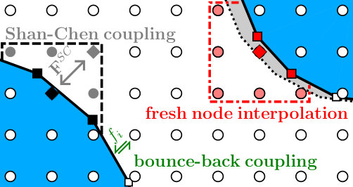 Figure 1
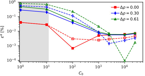 Figure 2
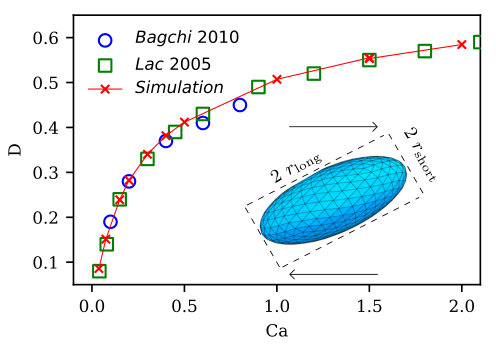 Figure 3
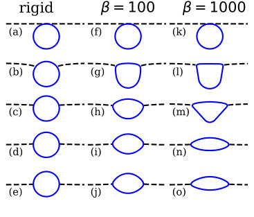 Figure 4
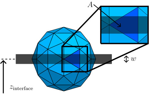 Figure 5
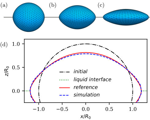 Figure 6
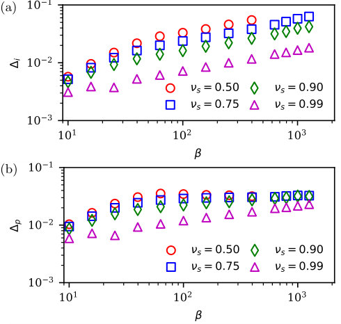 Figure 7
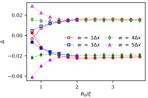 Figure 8
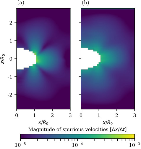 Figure 9
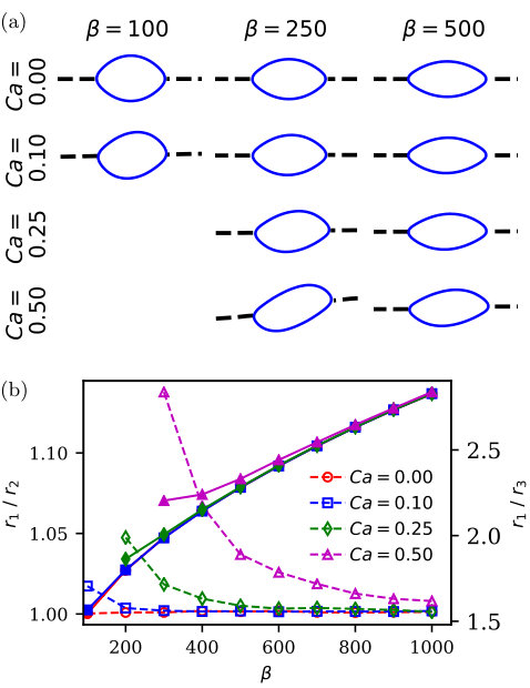 Figure 10
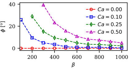 Figure 11
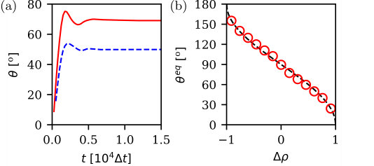 Figure 12
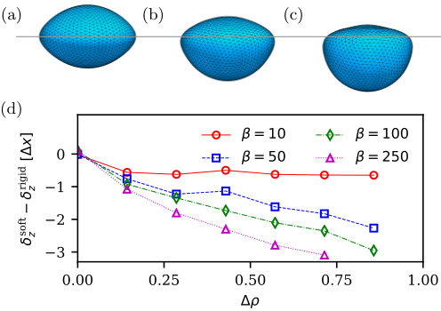 Figure 13
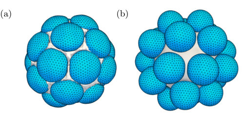 Figure 14
Peer Reviews
No public reviews on file for this paper yet. If you reviewed it on a platform where reviews are public (OpenReview, ICLR, NeurIPS, ICML), you can paste yours below so the community can read it here.
Videos
No videos yet. Explain this paper in a talk, walkthrough, or lecture? Add one.
Mesoscale simulation of soft particles with tunable contact angle in multi-component fluids
Maarten Wouters
Department of Applied Physics, Eindhoven University of Technology, De Rondom 70, 5612 AP, Eindhoven, The Netherlands
Othmane Aouane
Helmholtz Institute Erlangen-Nürnberg for Renewable Energy, Forschungszentrum Jülich, Fürther Strasse 248, Nürnberg, Germany
Timm Krüger
School of Engineering, Institute for Multiscale Thermofluids, The University of Edinburgh, Edinburgh EH9 3FB, Scotland, UK
Jens Harting
Helmholtz Institute Erlangen-Nürnberg for Renewable Energy, Forschungszentrum Jülich, Fürther Strasse 248, Nürnberg, Germany
Department of Applied Physics, Eindhoven University of Technology, De Rondom 70, 5612 AP, Eindhoven, the Netherlands
Abstract
Soft particles at fluid interfaces play an important role in many aspects of our daily life, such as the food industry, paints and coatings, and medical applications. Analytical methods are not capable of describing the emergent effects of the complex dynamics of suspensions of many soft particles, whereas experiments typically either only capture bulk properties or require invasive methods. Computational methods are therefore a great tool to complement experimental work. However, an efficient and versatile numerical method is needed to model dense suspensions of many soft particles. In this article we propose a method to simulate soft particles in a multi-component fluid, both at and near fluid-fluid interfaces, based on the lattice Boltzmann method, and characterize the error stemming from the fluid-structure coupling for the particle equilibrium shape when adsorbed onto a fluid-fluid interface. Furthermore, we characterize the influence of the preferential contact angle of the particle surface and the particle softness on the vertical displacement of the center of mass relative to the fluid interface. Finally, we demonstrate the capability of our model by simulating a soft capsule adsorbing onto a fluid-fluid interface with a shear flow parallel to the interface, and the covering of a droplet suspended in another fluid by soft particles with different wettability.
I Introduction
In many fields soft particles at interfaces play an important role, for example medical applications Levy1990 ; Constantinides1995 , cosmetics Puglia2012 , food industry Silva2012 , and paints and coatings Kooij2016 ; Keddie2010 . For a single particle one can still analytically describe simple systems. However, when multiple particles interact with each other, it is typically no longer possible to predict the deformation dynamics of the individual particles, especially when fluid-fluid or fluid-vapor interfaces are present.
Computational methods can be of great value to complement experiments and to characterize emergent phenomena stemming from the complex particle-particle and particle-fluid interactions, such as the margination of platelets in blood-flow Krueger2016 ; Mehrabi2016 , the rheology of a suspension of soft capsules Gross2014 ; MacMeccan2009 ; Krueger2014 , or the stabilization of emulsions with (solid) nano-particles Frijters2012 ; Gunther2014 .
Simulating soft particles at fluid interfaces can be done on the microscopic scale, with for instance molecular dynamics simulations where one resolves the polymer chains or molecules which make up the soft particle Mehrabian2016 . Such methods are, however, extremely costly, and therefore limited to simulations of only a few particles. Macroscopic methods typically directly solve the Navier-Stokes equations, or a coupled set of equations, discretized onto a grid to make it numerically accessible, such as for example finite element methods. To properly describe fluid-structure interactions this often requires expensive re-meshing steps and thereby becomes increasingly complex to solve, both in implementation and computational effort Zienkiewicz2014 .
Our goal is an efficient method which makes large-scale simulations of suspensions of soft particles feasible on existing high-performance computing clusters, and offers the possibility to easily extend the simulated system to more complex cases. The mesoscopic lattice Boltzmann method (LBM) is a suitable candidate since it is straightforward to implement and has proven its capability of efficiently simulating large systems of suspended particles in a fluid Ladd2001 ; Aidun2010 ; Harting2004 .
Simulations of soft particles in a single-component fluid are well established in the LBM literature. Typical examples are fluid-filled capsules and cells MacMeccan2009 ; Krueger2011a ; Gross2014 ; Gekle2017 , vesicles Kaoui11 ; Farutin2018 ; Halliday2016 , and particles with three-dimensional elasticity Buxton2001 ; Wu2010_2 . Comparably, there are various approaches to model rigid particles in multi-component fluids. Several authors apply the momentum exchange method introduced by Ladd Ladd1994_1 ; Ladd2001 for the solid particle, coupled to the pseudo-potential multi-component fluid method of Shan and Chen Joshi2009 ; Jansen2011 ; Frijters2014 ; Cheng2017 or a free-energy based multi-component model Stratford2005 ; Connington2015 . Other methods for the fluid-structure coupling exist as well, such as fluid particle dynamics Tanaka2000 , or the immersed boundary method Feng2004 ; Wu2009 .
Despite the abundance of methods for rigid colloids in multi-component fluids, the simulation of soft particles in multi-component fluids is still sparse in the LBM literature. Li et al. Li2016 coupled the pseudo-potential method of Shan and Chen Shan1993 ; Shan1995 with the immersed boundary method of Peskin Peskin1972 . Pepona et al. Pepona2019 have recently presented a two-dimensional model for soft particles at fluid-fluid interfaces based on the free-energy LBM coupled with immersed boundaries. The immersed boundary method interpolates the local velocity around each boundary node via an interpolation stencil in order to acquire the velocity of the boundary node. Overlap of these interpolation stencils is inherent to the model, resulting in a small mass-flux through the boundary. Li used an improved scheme which corrects for the overlap of the stencils in order to ensure the no-slip condition at moving solid boundaries Pinelli2010 , and finally applied the method to deformable cilia, which are partially at the interface between two fluids. Their method is however costly due to the need of inverting a square matrix of the size of the number of discretization points for the boundary. Since their cilia are discretized with roughly 20 boundary nodes, this does not pose a significant problem for the computational efficiency. However, for systems with many soft particles in which a single particle can typically have of the order of boundary nodes, the impact of this matrix inversion quickly becomes a computational bottleneck.
In this work we propose an alternative approach which is capable of describing soft particles with a tunable contact angle, in three dimensional multi-component fluids in large and/or dense systems. It combines several existing methods commonly used in the LBM literature. Our basis is the momentum exchange bounce-back fluid-structure coupling as introduced by Ladd Ladd1994_1 ; Ladd2001 , coupled to soft particles in a similar manner as introduced for single-component systems by Aidun et al. Reasor2011 ; MacMeccan2009 ; Cheng2017 ; Aidun2010 . This is then coupled to the popular multi-component pseudo-potential method of Shan and Chen (SC) Shan1993 ; Shan1995 and allows for tunable preferential contact angles of the particle surface via an effective off-set in the densities used for the force calculations as introduced by Jansen et al. Jansen2011 .
The presented method has the benefit that the no-mass-flux condition across the particle boundary is guaranteed inherently thanks to the bounce-back conditions. Furthermore, the fluid-structure coupling is independent of the collision step of the LBM and the chosen constitutive models for the soft particles, which ensures a lot of freedom for future extensions or adaptations of the model. Finally, our method allows to tune properties at the level of the used discretization of the boundary, opening the possibility to for example simulate soft particles with inhomogeneous wetting properties across the surface.
For clarity, we present the method in the most simple implementation possible and refer to the existing literature for possible extensions and improvements. We use the Skalak (SK) hyperelastic constitutive law Skalak1973 to model the fluid-filled capsules throughout this work, but we emphasize that other existing soft particle models Barthes2016 ; Biben2011 ; Buxton2001 can be applied straightforwardly as well.
The remainder of the paper is structured as follows. In section II we introduce the simulation method and provide brief summaries of the different existing models combined in our approach. We validate our method in section III. First, the deformation of a single capsule in shear flow is compared to previously reported values in the literature. Then, the error in the equilibrium shape of capsules adsorbed onto a fluid-fluid interfaces is studied, where we compare our data to a reference model to explicitly exclude all causes of errors other than the used fluid-structure coupling, since the used models for soft particles are already well reported in literature. Also the influence of a shear flow parallel to the fluid-fluid interface on the steady-state shape of a soft particle is briefly studied. Furthermore, we demonstrate the possibilities of our method by simulating the adsorption of soft capsules with different wettability onto a droplet. Finally, we summarize and discuss our results in section IV.
II Method
II.1 The lattice Boltzmann method
To simulate the dynamics of the fluids, we apply the lattice Boltzmann method (LBM). It allows for a straightforward implementation and has proven its capability to handle a wide variety of fluid dynamics problems Benzi1992 ; Succi2001 ; Bible . Thanks to the locality of the algorithm it is also well suited for a parallel implementation and high performance computing applications Aidun2010 ; Harting2004 .
The LBM is based on the discretization of the Boltzmann equation, where we discretize space into a regular 3D lattice with positions and lattice spacing , and the time into evenly spaced time steps with step size . Additionally, we discretize the velocity space with 19 discrete lattice velocities (D3Q19 model). Using the Bhatnagar-Gross-Krook (BGK) collision operator Bhatnagar1954 the time evolution of the single-particle probability distribution function is described by
[TABLE]
where is a relaxation time associated with the kinematic viscosity as , and is the speed of sound.
The left-hand side of Eq. 1 describes the streaming step during which the distribution functions are streamed from fluid node along their respective lattice directions to the neighboring fluid node . The right hand side denotes the inter-molecular collisions and resulting relaxation towards a local equilibrium distribution with characteristic timescale . We use a second order accurate approximation for the equilibrium distribution , given as
[TABLE]
where the lattice weights are defined as
[TABLE]
to ensure isotropy.
We include forces acting on the fluid as a shift in the equilibrium velocity in Eq. 2 Shan1993 . From the distribution function the local macroscopic density and velocity can now be computed as
[TABLE]
where is an arbitrary scaling factor for the mass density of the fluid, which is fixed to unity throughout this work. For more details and an extensive derivation of the LBM we refer the interested reader to Bible ; Succi2001 .
II.2 Soft particle model
We consider a fluid-filled capsule modeled as a two-dimensional incompressible hyperelastic membrane discretized into regular triangular finite elements. The membrane mechanical properties depend on the chosen hyperelastic law. We use in this work the Skalak constitutive model which provides the membrane with resistance to local area dilatation and shear elasticity Skalak1973 . The corresponding strain energy reads as
[TABLE]
where is the shear elastic modulus, and are the strain invariants of the deformation tensor, and and are the principal stretching ratios. is a parameter controlling the local inextensibility of the membrane and is related to the area dilation modulus by . In the asymptotic limit of small deformation, the 2D Poisson ratio can be expressed as function of such as with Barthes2016 . A constraint on the volume variation is enforced using a penalty function given by
[TABLE]
with a volume-change resistance modulus, and the reference volume of the stress-free particle. The strain and volume forces are computed from their respective energy terms via the principle of virtual work Charrier1989 ; Shrivastava1993 , where the force for each individual boundary node is computed using
[TABLE]
The membrane can be endowed with a bending resistance to out of plane deformation by means of the Helfrich free energy Helfrich1973 given by
[TABLE]
where is the bending modulus, and are the mean and spontaneous curvatures, respectively. For the sake of simplicity the spontaneous curvature is neglected in this study. The bending surface force density is obtained from the functional derivative of Eq. 9 and reads as
[TABLE]
where is the Gaussian curvature, is the Laplace-Beltrami operator, and is the normal vector pointing outward from the particle surface. The nodal bending force is obtained by multiplying Eq. 10 with the corresponding nodal area (Voronoi area). , , and are computed using the discrete differential-geometry operators approach as detailed in Meyer et al. Meyer2003 . We define the dimensionless bending parameter , and fix it throughout this work to unless specified otherwise.
We apply a first-order accurate forward Euler scheme for the movement of the boundary nodes, to prevent the costly need to re-calculate all the forces acting on the boundary nodes at a higher rate than the LBM updates, as it would be required by sub-step integration techniques. Higher order time-integration schemes can be used as well, but were found unnecessary for the presented work.
The proposed simulation method of this work can easily be applied to different types of soft particles, such as fluid-filled elastic capsules Barthes2002 ; Barthes2016 , vesicles Biben2011 , or soft elastic particles with 3D elasticity Buxton2001 . For the latter 3D elastic particles one actually introduces a cross-linked lattice of boundary nodes, rather than a 2D membrane.
II.3 Fluid-structure coupling
Exact boundary conditions, which prevent any mass-flux through the particle surface, are desirable for a correct physical model. For single-component fluids a small mass-flux is however typically mitigated by the pressure, where the results can be considered tolerable based on the required accuracy. For a multi-component fluid the requirement of exact boundary conditions is more important, since the interior and exterior fluid of the particle typically have a different composition, where the mass-flux through its surface could for example trigger the formation of droplets. Hence, we ensure that no mass moves through the surface by applying bounce-back boundary conditions for distribution functions that cross a boundary element during the streaming step. We use the half-way bounce-back scheme (BB), as already used for the simulation of soft particle suspensions in single-component fluids MacMeccan2009 ; Reasor2011 ; Clausen2010 , which bounces the incoming distribution functions from a fluid node onto a boundary element back during the streaming step as Ladd1994_1
[TABLE]
where the superscript ∗ indicates the post-collision state, , is taken as the local density at fluid node , and is the velocity of the boundary element.
The momentum transfer onto the boundary is given by the difference of the incoming and outgoing population as
[TABLE]
In the presented work the coupling of quantities between the boundary elements and boundary nodes is done via a homogeneous scheme where the three nodes of only the corresponding boundary element are given the same weighting factor. This technique maintains the locality of the algorithm by eliminating the need to communicate properties of the boundary node of the neighbouring boundary elements. Alternatively, both Buxton et al. Buxton2005 and MacMeccan et al. MacMeccan2009 introduced different weighting schemes for the spreading of the exchanged momentum to boundary nodes for all nodes within a characteristic distance. However, no differences were observed on the time scale of equilibration for all presented simulations. Hence, for the sake of brevity a thorough characterisation of this free parameter is left for future work. Also the interplay with the error stemming from the half-way bounce-back as compared to more accurate methods should be included in such a study.
The half-way bounce back method as given in Eq. 11 is known to suffer from staggered momenta Ladd1994_1 ; Ginzbourg1996 ; Khirevich2015 . Especially in small enclosed volumes, such as our fluid-filled capsule, these momenta rapidly manifest themselves as a staggering in the velocity field. In this work we prevent this by spreading the total exchanged momentum from the half-way bounce-back coupling homogeneously over two consecutive time steps Ladd1994_1 .
The staggered momenta can also be prevented by using full-way bounce-back Sukop2006 , where the boundary is still approximately half-way between two fluid nodes, but the populations travel the complete distance between two fluid nodes and are reversed during the next collision step. However, for the full-way bounce-back one needs to store the populations that pass a boundary element, which is impracticable when there are fluid nodes on both sides of the boundary. Alternatively, one could also increase the accuracy of the discretization of the boundary with interpolated bounce-back boundary conditions Bouzidi2001 , multi-reflection boundary conditions Ginzburg2003 , or the one-point second-order bounce-back boundary condition Tao2018 . They do offer a better representation of the boundary on the fluid lattice, and remove the force fluctuations that stem from the jump that the location of the discretized boundary makes when a boundary element moves past a fluid node in the half-way bounce-back algorithm. However, they are computationally more expensive since one needs to calculate the exact distance between a fluid node and the boundary element along the lattice vectors. Furthermore, the interpolated bounce-back and multi-reflection boundary conditions use information of multiple fluid nodes, which increases the minimum separation between two adjacent particles. Hence, the half-way bounce-back algorithm with the coupling proposed by Ladd Ladd1994_1 and a first-order accurate time-integration scheme is deemed most effective for applications involving large systems, where the particles could become densely packed.
II.4 Multi-component fluid interactions
To describe multi-component fluids we use the pseudo-potential method of Shan and Chen Shan1993 ; Shan1995 . For each component we individually solve Eq. 1. In order to couple the different components a repulsive fluid interaction force is added between opposing fluid components and at neighboring fluid nodes, as given by
[TABLE]
where is a pseudo-potential, and is the fluid interaction strength. For the current work we chose and limit the number of components to 2.
The interior and exterior fluid are decoupled at the boundary via the bounce-back boundary conditions. Therefore, we also decouple the interior and exterior fluid interaction forces. In order to satisfy continuity close to the boundary, we interpolate the neighboring fluid densities located on the opposing side of a boundary
[TABLE]
where runs over all fluid nodes on the opposite side of the boundary as , as schematically indicated in Fig. 1. This way we interpolate the densities for the ring of fluid nodes just outside our boundary for the inner fluid, and the ring of fluid nodes just inside the boundary when calculating the fluid interaction force on the fluid nodes just outside the boundary. In order to conserve momentum the resulting force that would act on the fluid node across the boundary is applied to the boundary element that separates the set of fluid nodes.
This also allows to tune the contact angle of the particle surface by adding an offset to one component of the interpolated densities of Eq. 14, as is proposed by Jansen et al. Jansen2011 . Since the density offset is only added to one of the two components, while the non-preferred fluid component is unchanged, we define the dimensionless particle color by normalizing the added virtual density offset as
[TABLE]
where and are the equilibrium majority and minority densities corresponding to the chosen initial densities in the system and the fluid interaction parameter . Here, a positive particle color indicates that the fluid density is added to the first fluid, whereas a negative particle color indicates the density added to the other fluid.
The benefit of decoupling the interior and exterior regions by use of the bounce-back boundary conditions, is that we do not need a third fluid component for the interior region of the particles. First, this will save a significant amount of computational resources. Secondly, the interior region of the particle can be given the same composition as the exterior region, which makes it easier to initialize systems where the hydrostatic pressure inside the particle equals that outside the particle for an un-deformed mesh. In the present work the interior of the particle is always initialized with the same fluid composition and fluid interaction strength as the exterior region when no fluid-fluid interfaces are present. When fluid-fluid interfaces are present, the composition equals that of the lower fluid layer. Careful checks validated that changing the interior composition to that of the upper fluid yields no difference in the presented results.
II.5 Fresh fluid nodes
One of the problems arising for moving boundaries is how to initialize fluid nodes when a boundary element moves over it, commonly referred to as fresh node treatment. For solid particles one can choose not to remove the fluid that becomes covered by a particle Ladd1994_1 , however for fluid-filled capsules this is not possible anymore. In this case the local fluid at a fresh fluid node needs to be removed and replaced by an appropriate representation of the fluid present on the other side of the boundary, whenever a boundary element passes a fluid node.
Several methods are possible for this, of which we use an interpolation method Aidun1998 ; Jansen2011 . The new density at the fresh fluid node is given by
[TABLE]
where the sum runs over all neighboring fluid nodes that are on the same side of the boundary as the fresh node, which are not fresh nodes themselves during that time step. This interpolation is schematically visualized in Fig. 1. As in Sec. II.3, the fresh fluid node is assigned the average velocity of the three boundary nodes of the nearest boundary element
[TABLE]
In order to locally conserve the combined momentum of the fluids and particles, the momentum of the removed fluid at the fresh node is added to the boundary element that moved over the node, while the momentum of the newly generated fluid is subtracted from the same element, similar as to the momentum exchange method for solid objects as introduced by Ladd Ladd2001 .
The interpolation as shown in Eq. 16 however fails to conserve the global mass in the system when there are forces or density gradients close to the boundary, which is always the case when the particle is near a fluid-fluid interface Jansen2011 ; Frijters2012 . Close to the particle surface the fluid interaction force results in a slightly lower density, and therefore the interpolation will always slightly over-estimate the local density. When the particle is close to the fluid interface, or has a preferential contact angle other than 90*∘*, this effect increases significantly. Since no analytical solution is readily available for the density profile around the surface, a correction which only uses local quantities is not feasible. Therefore, we apply an adaptive mass-correction term which scales the density of fresh fluid nodes as Jansen2011 ; Frijters2012
[TABLE]
where is the total volume of all fluid nodes in the system, is a parameter used to tune the strength of the adaptive correction, is the average initial density of component in the entire system, and is the averaged density obtained by Eq. 16. We limit between the smallest and largest density value of its neighbors Frijters2012 .
In Fig. 2 we show the error in the total mass after 250.000 simulation steps for a system where a perfectly rigid particle adsorbed onto a fluid-fluid interface is propagated parallel to this interface. The particle movement is imposed by fixing the velocity of each boundary node to . Independent of the wetting properties of the particle, the relative error of each individual component is below 0.01% when . Hence, is used throughout this work independent of the used particle colour.
III Results
Throughout this entire section we fix the characteristic timescale , the reference density , and the discretized time and length scales and to unity. However, for clarity purposes we will denote the non-dimensionalized lengths and times in units of and . Unless specified otherwise, the fluid interaction strength is set as , and the initial majority and minority densities are set as and , which yields a fluid-fluid surface tension of . The particles are discretized with boundary elements, and boundary nodes, where each boundary node is assigned a mass of 5. The fluid encapsulated by the particle is initialized with the same composition and fluid interaction strength as the lower fluid.
III.1 Soft capsule in shear flow
As a first validation of the fluid-structure coupling we simulate the deformation of a capsule in a linear shear flow. We define the capillary number as
[TABLE]
where is the summed fluid density of both components, and is the shear rate. We initialize a single particle with a radius , a shear elasticity , and local extensibility (i.e. and ) at the center of a cubic domain of fluid nodes with a homogeneous binary fluid-mixture of . The interaction strength is set to =0.0 mimicking a homogeneous mixture of non-interacting fluids. A constant shear rate is imposed at the top and bottom -planes via an on-site velocity boundary conditions Zou1997 ; Hecht2010 . The capillary number is varied by changing the shear elasticity while keeping the shear rate constant at .
For different shear rates we measure the steady-state Taylor deformation parameter
[TABLE]
where and are the length of the long and short half-axis, respectively. The lengths of these axes are obtained from the tensor of inertia of the boundary surface Ramanujan1998 . As shown in Fig. 3 our simulations show an excellent agreement with the results reported by Lac et al. Lac2005 and Bagchi et al. Bagchi2010 over a wide range of capillary numbers. As expected, this indicates that in the absence of a fluid interaction force we obtain the correct physics when switching from a single-component fluid to a multi-component fluid.
III.2 Adsorption onto a fluid-fluid interface
In this section we show the capability of our method to model the adsorption of soft particles at fluid-fluid interfaces, and aim to characterize the error stemming from the coupling between the multi-component fluid and the bounce-back boundary conditions for soft particles. Soft particles adsorb onto nearby fluid-fluid interfaces in order to minimize the interfacial energy. For rigid particles the interplay between the inertia of the particle and the surface tension of the fluid-fluid interface dominates the adsorption dynamics. Soft particles have another degree of freedom, namely the softness of the particle.
All simulations in this section are performed in a system with a fluid-fluid interface in the -plane, located at in a cubic domain of fluid nodes. The system is closed at the top and bottom with rigid boundaries using the half-way bounce-back scheme, and periodic boundary conditions in the other directions.
We define the dimensionless softness parameter of the capsule at a fluid-fluid interface as . Unless specified otherwise we initialize the particles with an initially spherical shape with and boundary elements. The volume conservation modulus is chosen on purpose at a large value of to ensure a quasi volume-incompressible capsule with fluctuations in the encapsulated volume in the order of 0.01% for all presented simulations. The exact choice here is however not significant for the presented work, and smaller moduli are possible as well.
In Fig. 4 we visualize the adsorption of a soft particle with and onto a fluid-fluid interface, compared against a rigid particle. For now we focus qualitatively on the dynamics of an adsorbing particle, and therefore only visualize the first 1600 time steps, in which the particles adsorbs onto the fluid-fluid interface and still shows a small, dampened movement around its final equilibrium position.
As expected from a physical viewpoint, we observe for all three cases a simultaneous downwards motion of the interface towards the particle surface, while the top of the particle extends at the fluid-fluid interface under the outward pull of the surface tension. Increasing the softness parameter appears to mitigate the downward movement of the interface, where the height difference of the fluid-fluid interface at the contact point and at the point farthest away from the particle is 2.3 for the rigid particle, 1.8 and respectively for the particle with and . This can be qualitatively explained by the fact that for very soft particles it is energetically more favorable to match the contact angle between the particle surface and fluid-fluid interface via deformation of the surface than via a deformation of the interface. It has to be noticed that the system-size here is relatively small to study such deformation effects. The capillary length can be multiple times larger than the particle radius, which requires larger system sizes. A more thorough and quantitative study of such effects is left for future work, and beyond the scope of the current paper.
Many different studies have already been performed on the accuracy of various constitutive models for the dynamics of soft particles. For instance, Ramanujan studied the deformation of capsules for various fluid viscosities Ramanujan1998 , Omori studied the correlation between spring network models and continuum constitutive laws Omori2011 , Barthès-Biesel extensively studied the deformation of various types of capsules Barthes2016 , and the discretization of bending algorithms was studied by both Guckenberger Guckenberger2017 and Tsubota Tsubota2014 . Hence, we purposefully attempt to isolate the error due to the fluid-structure coupling, which is the new part proposed in this work, from those stemming from the method used to model the elastic boundaries.
For this purpose we design a reference model that uses the same routines as our implemented code as presented in section II, but disables the hydrodynamics by ignoring all routines related to the LBM. Instead of the hydrodynamic force of LBM, we directly apply the tensile force of the surface tension acting on the particle surface on all boundary elements within a width of a stationary emulated position of the interface. The emulated tensile force on a boundary element is computed from the area of the boundary element covered by the emulated interface as
[TABLE]
where is the area of the boundary element which lies between two planes within a distance of the emulated interface position , and is the fluid-fluid surface tension. The determination of the area is schematically visualized in Fig. 5. The emulated tensile force is distributed homogeneously over the three boundary nodes which span the boundary element. We set the width , equal to the characteristic length scale of the fluid lattice, unless specified otherwise.
The reference model uses exactly the same elastic laws, the same discretization of the particle surface, and the boundary nodes are updated with the same time integration scheme. The input values for the surface tension are obtained from separate simulations mimicking a Laplace test, which relate the pressure difference of a droplet for a specific interaction parameter with the droplet radius (data not shown) Frijters2012 . This reference model a priori excludes sources of errors other than the fluid-structure coupling, and allows us to compare the simulation results directly against the deformation of any constitutive elastic law already established in the literature.
To quantify the error of our results we use the extrema of the particle at the poles and at the fluid-fluid interface , where is the equilibrium half-axis in the plane perpendicular to the fluid-fluid interface, and the equilibrium half-axis in the plane parallel to the fluid-fluid interface. The errors are then defined as the normalized difference between the reference case and our simulation method as
[TABLE]
since due to the bending rigidity the entire shape is characterized by these extrema in equilibrium. The extrema and can be obtained directly from the tensor of inertia, similar as done for Taylor deformation parameter of Fig. 3. In this manner the errors and provide an intuitive dimensionless measure for the error stemming from the fluid-structure coupling.
In Fig. 6, we visualize the obtained equilibrium shapes for a Poisson ratio and softness parameters of 10, 100, and 1000 to elucidate the used parameters. Furthermore, we visualize a comparison of the obtained equilibrium shape between our simulation method and the reference simulation for . The particle is stretched to and , with corresponding errors of and .
Over a wide range of softness parameters and Poisson ratios we observe an excellent agreement with the reference model, as shown in Fig. 7. For and the ratio between the axis in the plane perpendicular and parallel to the fluid-fluid interface is 2.3, with an absolute mismatch at the fluid-fluid interface of only , which is considered as excellent agreement when considering the accuracy of the used half-way bounce-back boundary conditions.
The increasing error for larger softness parameters can be understood by considering the minor-axis of the particle perpendicular to the fluid-fluid interface, which decreases for an increased softness and approaches the diffuse interface width of the multi-component model for very large softness parameters. The largest deformation is observed for a particle with and , where the minor axis decreases down to 3.6 and the errors with an emulated width of 1 read and at the poles and interface respectively. The typical width of the diffuse interface for the used interaction parameter is . When we increase the emulated width of the interface, we indeed observe a decrease in the error at both the poles and the interface, where for an emulated width of the errors reduce to and . As can be seen in Fig. 8 the errors for particles with a very large initial radius are only weakly dependent on the particle radius and appear to approach a uniform value independent of the emulated interface width when . For smaller intermediate particle radii the importance of the diffuse interface becomes apparent, where the errors with a very low emulated width become strongly dependent on the ratio of the particle radius and diffuse interface width.
To verify the Galilean invariance of the presented method, a soft particle with and adsorped onto a fluid-fluid interface is studied where the top and bottom plane of the system are driven with a constant velocity parallel to the interface. In order to exclude effects from the initial acceleration of the particle, the simulation is run for 500,000 simulation steps, of which the last 50,000 are sampled every 5,000 steps. No observable differences were found in the particle shape, and the pressure inside and around the particle only shows a relative difference of 0.03%. Due to the pseudo-potential multi-component fluid method, spurious currents are present near the contact point of the particle boundary with the fluid-fluid interface, similar to the spurious currents that are known to persist indefinitely near the curved fluid-fluid interfaces. Small differences occur in the fluid velocities around the contact point on the time scale of as a result of the continuously changing discretisation of the particle boundary on the fluid lattice. These stem from the half-way bounce-back scheme, which is known to induce local force fluctuations whenever a boundary element jumps over a fluid node. In Fig. 9 we compare the magnitude of the spurious velocities for a stationary particle and a particle moving along with the system with velocity . Here, it can be observed that the spurious currents do not show an increase in magnitude, but do show a minor increase in their extent. However, for the current work we deem the accuracy of the half-way bounce-back scheme sufficient. In future works, when a higher accuracy is required, the errors stemming from the changing discretisation of the particle boundary on the fluid lattice could be mitigated by using a fluid-structure coupling scheme with a higher accuracy. Similarly, the effect of the spurious currents could be reduced by exchanging the multi-component model for a scheme with reduced spurious currents.
III.3 Soft capsule at an interface under shear
In this section we briefly demonstrate how the presented method can be used to study the dynamics of a system with shearing boundary conditions with a soft capsule adsorbed onto a fluid-fluid in the center of the system, where the shear is applied parallel to the interface. We initialize the system domain with 180 fluid nodes in both directions parallel to the fluid-fluid interface and 87 fluid sites perpendicular, where the odd numbered system height is chosen in order to easily initialize the interface exactly half-way between the shearing boundaries. To disable fluid-fluid interactions between the top and bottom plane these are initialized with non-moving bounce-back boundaries. On-site velocity boundary conditions are applied on the two planes of fluid nodes next to these boundaries to impose the shear velocities Zou1997 ; Hecht2010 .
When no shear is applied, i.e. , the particle has two symmetric major semi-axes parallel to the fluid-fluid interface and one minor semi-axis perpendicular to the interface, similar as previously visualized in Fig. 6. In the top panel of Fig. 10 we show the steady-state shape of the particle and the interface for different capillary numbers and softness parameters. Here, it can be observed that the symmetry is broken when the system is sheared, and the major semi-axis parallel to the shear flow elongates. In the bottom panel of Fig. 10 we visualize the ratio between these two axes (the solid lines and symbols), and it can be clearly seen that the asymmetry for the two largest axes increases for increasing capillary numbers and decreasing particle softness. Simultaneously, the ratio between the major and minor axis deviates stronger from the base curve set by for lower softness parameters when the capillary number is increased, while for large softness parameters the ratio becomes independent of the capillary number. Intuitively this can be explained by the fact that softer particles have less area perpendicular to the shear flow, and therefore experience a lower stress from the shear flow. This results in a lower tank-treading velocity of the membrane, which is indeed observed in the simulations (data not shown).
In Fig. 11 we show the angle between the largest semi-axis and the horizontal plane (i.e. the undisturbed fluid-fluid interface), which increases for increasing capillary numbers and decreasing softness parameters. This rotation of the inertial tensor semi-axes and the corresponding asymmetry in the particle shape also influences the fluid-fluid interface, as can be seen in Fig. 10 for and . Here one can observe the dynamical wetting of the particle surface, where the interface rises on one side of the particle while lowering on the other side in a symmetric manner due to the rotational velocity of the particle surface. Qualitatively this fits with the expectations from experiments and simulations on similar systems with rigid particles Capelli2015 , where the additional asymmetric deformation of the particle appears to allow a stronger deformation of the interface. A more detailed and thorough analysis of this phenomenon, including the effect of the preferential contact angle of the particle boundary, is left for future work.
III.4 Tunable contact angles
Similar to the work of Jansen et al. Jansen2011 our model is capable of tuning the preferential contact angle of the particle surface with the fluid-fluid interface. A positive particle color is expected to result in the particle preferring one phase over the other phase, and a change from the contact angle. For a rigid sphere with radius the contact angle can be measured by the distance between the center of mass of the particle and the position of the interface as
[TABLE]
The particle is initially submerged in its preferred fluid component with the particle surface penetrating the fluid-fluid interface by roughly 1. A rapid movement towards the equilibrium position, with some minor oscillations as a result of the inertia of the particle, can be observed as shown in Fig. 12.
From Young’s equation the contact angle is given by the balance of the interfacial tensions and between the particle and two fluid components, and the tension between the two fluid components
[TABLE]
For a neutral particle color the fluid-structure tensions are symmetric and negate the nominator of Eq. 24. The virtual fluid density added to the fluid interaction force by a non-zero particle color increases the asymmetry in the two fluid-structure interfacial tensions and can be expected to yield a scaling of the equilibrium contact angle as
[TABLE]
As seen in the right panel of Fig. 12, the measured equilibrium contact angle of a rigid spherical boundary shows a good agreement with Eq. 25.
For rigid particles at a fluid-fluid interface the vertical displacement is the only mechanism that allows for the match of the preferential contact angle of the particle surface without deforming the interface. Soft particles, however, can also deform in order to match the preferential contact angle. Thus, for larger values for the particle color the equilibrium shape turns into a hazelnut shape, as depicted in Fig. 13. This deformation simultaneously decreases the vertical displacement needed to match the preferential contact angle with the interface. In Fig. 13 we clearly observe the influence of the particle softness on the displacement as compared to a rigid particle with an equal particle color , where the particle displacement reduces for increasing softness parameters. For and the difference in displacement is almost 30% of the particle radius, while for relatively stiff capsules with the change in vertical displacement is only observed for low particle color values and reaches a constant difference for .
III.5 A droplet covered with soft particles
To further demonstrate the capability of our method to simulate the interplay between soft particles and fluid-fluid interfaces, we simulate the covering of a droplet of radius suspended in another fluid by 24 soft capsules with , , and . The particle centers are initialized on a sphere with radius , such that each particle slightly penetrates the droplet. Two different simulations are shown, one with hydrophilic particles with and another with hydrophobic particles with . A short range repulsive hard-core particle-particle interaction force is added between boundary nodes of opposing particles to prevent the overlap of the particles
[TABLE]
where is a constant parameter fixed here to , is the separation distance between the two boundary nodes, and is a cut-off distance for the interaction force. The exact shape of the repulsive force is however unimportant as long as it is sufficiently strong to prevent the overlap of the particles.
In Fig. 14 we compare the obtained configurations of both simulations after . The hydrophilic particles are almost completely pulled inside the droplet, covering nearly the entire surface of the droplet. Due to the close-packing at the interface, the hydrophilic particles cannot obtain the preferred hazelnut shape as shown in Fig. 13, and the deformation is also significantly influenced by the interactions with other particles. The hydrophobic particles only slightly penetrate the surface of the droplet, resulting in a more compact droplet and a larger surface area uncovered by particles. A detailed investigation of this system goes beyond the scope of this work and will be presented in a future paper.
IV Conclusion and discussion
We have presented a method capable of simulating soft particles in multi-component fluids, where we combined the bounce-back fluid-structure coupling with the multi-component fluid model of Shan and Chen. By using a specially designed reference model, the method has been shown to achieve an excellent agreement for the deformation of a Skalak capsule at a fluid-fluid interface, where the errors stemming from the coupling between the multi-component fluid and the particle surface are well below the characteristic length scale of the discretized fluid lattice. Despite the diffuse interface of the used multi-component model, a good agreement is still observed for the equilibrium shapes of particles with radii comparable to the diffuse interface width.
The used fluid-structure coupling furthermore allows one to easily tune the contact angle of a single particle over a wide range of contact angles. It has been shown that the softness of the particle has a significant influence on the vertical displacement of the center of mass of the particle relative to the fluid interface, resulting from the additional deformation of the particle.
All individual simulations shown in this work can be comfortably run on a modern desktop, leaving ample room to increase the system size and number of modeled particles when using modern high-performance clusters. The implemented code has been successfully tested for large systems with up to 2000 particles on available high-performance computing clusters, and therefore paves the way to investigate a variety of systems where both fluid-interfaces and the softness of suspended particles play a significant role.
There are also multiple opportunities to straightforwardly increase the level of complexity in the modeled systems within the presented method. For example, one can trivially move into the direction of inhomogeneous wetting particle surfaces, i.e. soft Janus particles, by defining the particle color individually on each boundary element. Furthermore, the bounce-back coupling can easily be altered to allow for a small permeability of the boundary by applying the bounce-back coupling only to a fraction of the distribution functions, allowing to model the slow release of the interior fluid of the soft capsules.
The half-way bounce-back coupling introduces the well-known staircasing effect in the discretization of the particle surface on the fluid lattice, thereby adding small discretization errors in the normal vector of the particle surface, which in turn result in small deviations of the expected equilibrium position. Furthermore, the bounce-back conditions introduce small force fluctuations in the force acting on the surface when the discretization on the fluid lattice changes (not shown in this paper). If desired, these effects can be mitigated by switching to higher order coupling schemes, such as interpolated bounce-back, but one needs to keep in mind that such methods break the local mass-conservation. During the development of the present method the small mass-errors from interpolated bounce-back schemes have been observed to quickly result in a drift of the mass in the system, since the density gradients close to the fluid interface are a priori large. In contrast to the mass change due to the fresh node interpolation, which was remedied by using the adaptive rescaling proposed by Jansen et al., the mass change from interpolated bounce-back also occurs for particles which are fixed in space and time. The used mass-correction term is unsuitable to correct for these errors, and devising another mass-conserving scheme without significantly afflicting the local fluid velocity is non-trivial. Hence, for the applications of dense suspensions the half-way bounce-back boundary condition is the most suitable, since it only requires a single fluid node between two adjacent particles, whereas the higher-order methods typically require two or three fluid nodes.
Acknowledgements.
Special thanks go out to Manuel Zellhöfer for help with various technical aspects during the code development. We acknowledge NWO/TTW (project 10018605), HPC-Europa3 (INFRAIA-2016-1-730897) and the DFG within the Cluster of Excellence ”Engineering of Advanced Materials” (project EXC315, Bridge funding) for available funding, and the Jülich Supercomputing Centre and the High Performance Computing Centre Stuttgart for the allocated CPU time. TK thanks the University of Edinburgh for the award of a Chancellor’s Fellowship.
The reference list from the paper itself. Each links out to its DOI / PubMed record.
- 1(1) P. P. Constantinides. Lipid microemulsions for improving drug dissolution and oral absorption: Physical and biopharmaceutical aspects. Pharmaceutical Research , 12(11):1561–1572, 1995.
- 2(2) M. Y. Levy and S. Benita. Drug release from submicronized o/w emulsion: a new in vitro kinetic evaluation model. International Journal of Pharmaceutics , 66(1-3):29 – 37, 1990.
- 3(3) C. Puglia and F. Bonina. Lipid nanoparticles as novel delivery systems for cosmetics and dermal pharmaceuticals. Expert Opinion on Drug Delivery , 9(4):429–441, 2012.
- 4(4) H. D. Silva, M. Â. Cerqueira, and A. A. Vicente. Nanoemulsions for food applications: Development and characterization. Food and Bioprocess Technology , 5(3):854–867, 2012.
- 5(5) J. Keddie and A. Routh. Fundamentals of latex film formation: processes and properties . Springer, 2010. ISBN 978-90-481-2844-0.
- 6(6) H. van der Kooij, G. van de Kerkhof, and J. Sprakel. A mechanistic view of drying suspension droplets. Soft Matter , 12(11):2858–2867, 2016.
- 7(7) T. Krüger. Effect of tube diameter and capillary number on platelet margination and near-wall dynamics. Rheologica Acta , 55(6):511–526, 2016.
- 8(8) M. Mehrabadi, D. N. Ku, and C. K. Aidun. Effects of shear rate, confinement, and particle parameters on margination in blood flow. Phys. Rev. E , 93(2):023109, 2016.