An inexpensive biasing system for use in electrostatic steering of ions
P. Schury

TL;DR
This paper presents a low-cost, compact electronic biasing device capable of superposing multiple high-voltage biases for ion beam steering, with digital control and potential for higher voltage operation.
Contribution
The authors introduce a novel, inexpensive biasing system with digital control, suitable for ion beam alignment in mass spectrometry applications.
Findings
Device can superpose 8 bias voltages up to ±96 V on a 5 kV main voltage.
System costs less than $500 USD to build.
Design can be extended for operation up to 20 kV with higher isolation components.
Abstract
We introduce a compact design for an electronic device capable of superposing 8 bias voltages up to 96~V on a voltage of up to 5~kV. Such a device has been implemented to provide biasing of a beam steerer-shifter system for use in aligning an ion beam with the optical axis of a multi-reflection time-of-flight mass spectrograph. The device features a 16-bit digital interface both to set and to monitor the applied voltages, and can be built for less than $500~USD. By selection of higher isolation components, the design concept can be extended to allow operation up to 20~kV.
Click any figure to enlarge with its caption.
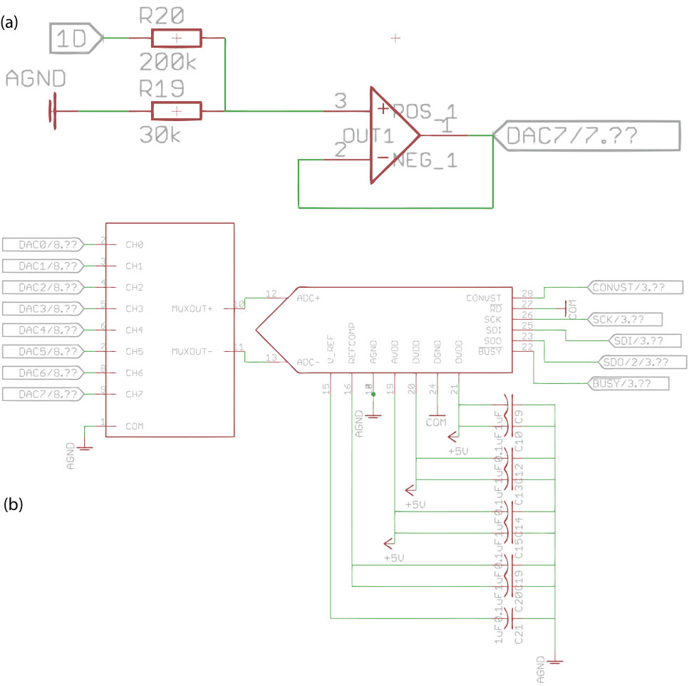 Figure 1
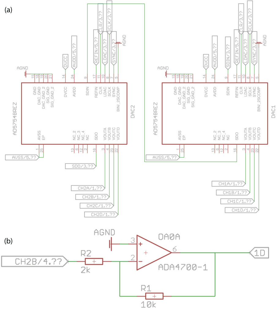 Figure 2
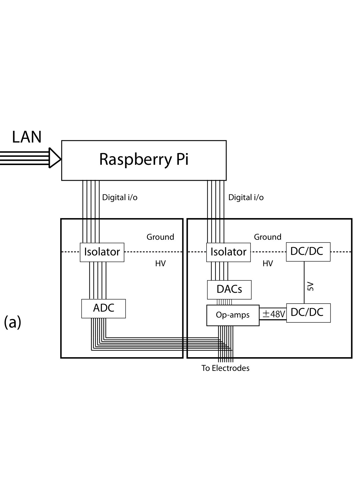 Figure 3
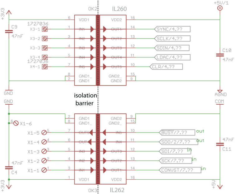 Figure 4
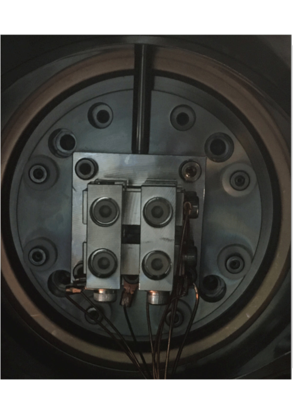 Figure 5
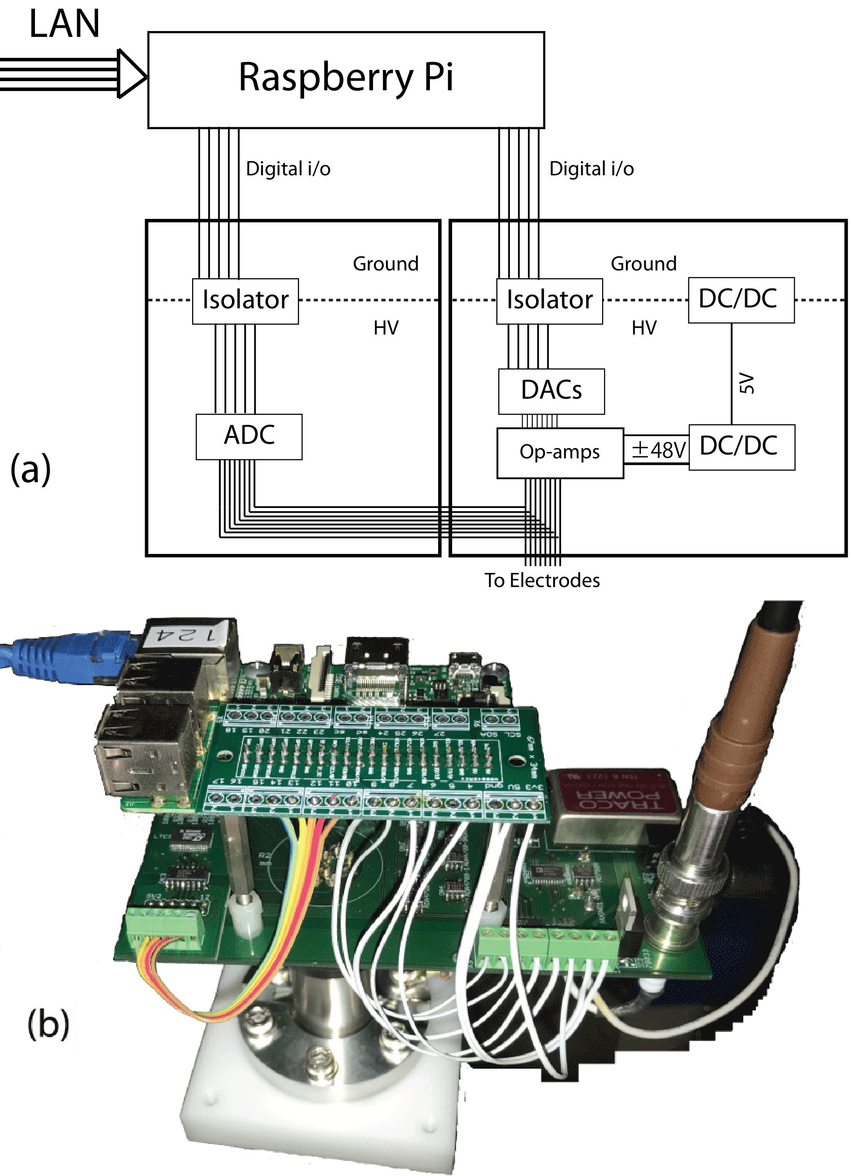 Figure 6
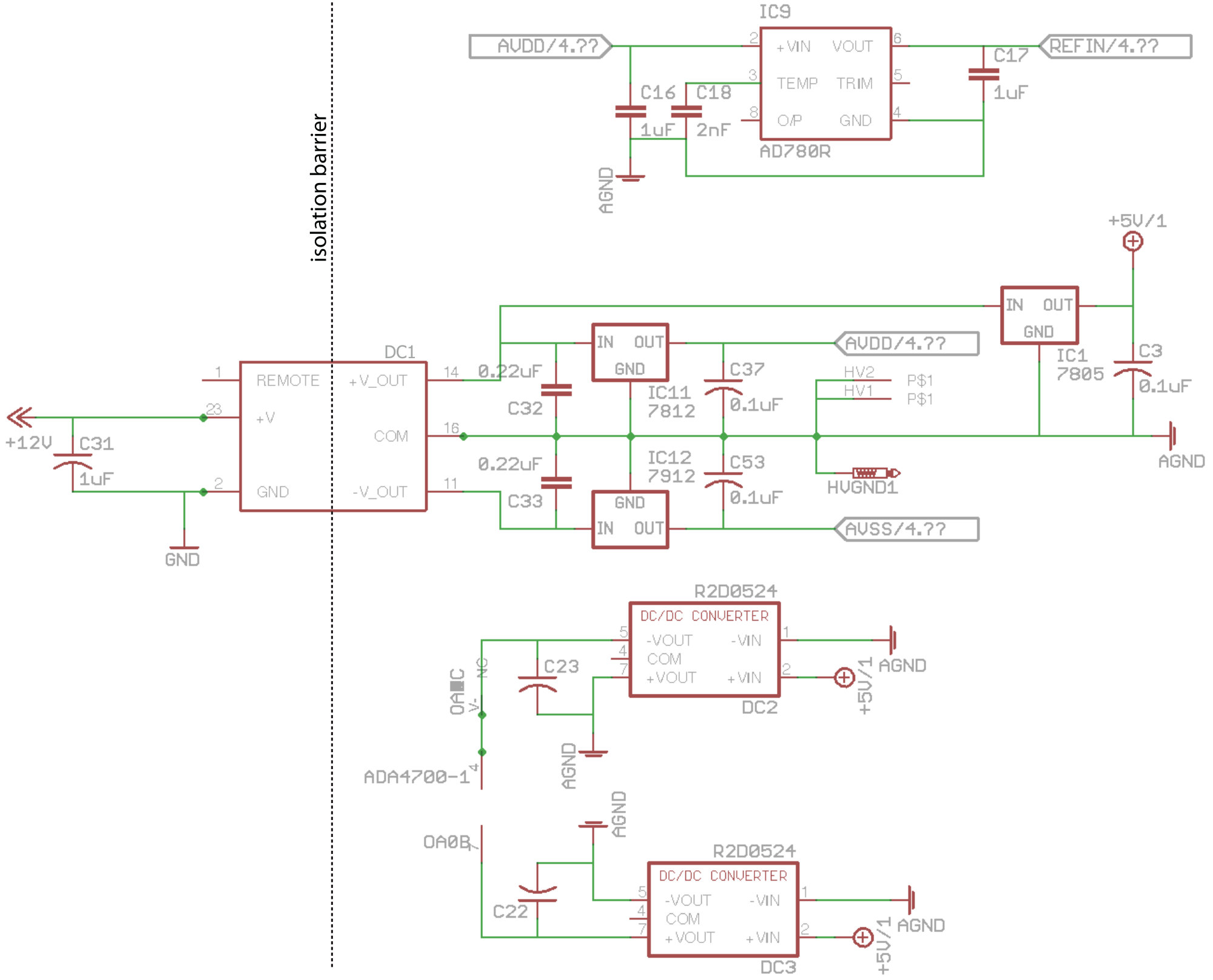 Figure 7
Peer Reviews
No public reviews on file for this paper yet. If you reviewed it on a platform where reviews are public (OpenReview, ICLR, NeurIPS, ICML), you can paste yours below so the community can read it here.
Videos
No videos yet. Explain this paper in a talk, walkthrough, or lecture? Add one.
An inexpensive biasing system for use in electrostatic steering of ions
P. Schury
M. Wada
Wako Nuclear Science Center (WNSC), Institute of Particle and Nuclear Studies (IPNS), High Energy Accelerator Research Organization (KEK), Wako, Saitama 351-0198, Japan
Abstract
We introduce a design for an electronic device capable of superposing 8 bias voltages up to 48V on a voltage of up to 1.5 kV. Such a device has been implemented to provide biasing of a beam steerer-shifter system for use in aligning an ion beam with the optical axis of a multi-reflection time-of-flight mass spectrograph. The device features a 16-bit digital interface both to set and to monitor the applied voltages, and can be built for less than $500 USD. By selection of higher isolation components, the design could allow operation up to 10 kV or more.
keywords:
Ion Optics , Electronics
††journal: TDB
1 Introduction
The ability to steer or axially shift an ion beam is crucial in most ion optical systems. If a steering element were to axially accelerate or decelerate the ion beam, it would act as a focusing element and induce a axial displacement dependent steering. To prevent such undesirable behavior, the steering element must be at the same nominal potential as the preceding optical element. Often, this requires such a steering system to have a nominal potential of several kilovolts.
One solution is to bias each element with an independent high-voltage supply. However, this quickly becomes prohibitively expensive. A common alternate solution, often employed when the beam line itself if on some high-voltage potential, is to use a high-voltage isolation transformer to “float" an array of digital-to-analog (DAC) circuits on the beam potential. In cases where the beam line is biased at some high-voltage potential, such a DAC system is generally a minor addition to other devices (vacuum pumps and gauges, ion detectors, etc.) which would be powered from such an isolation transformer. However, in a case where the beam line is not biased, it is an expensive and bulky option that must be accompanied by optical isolation for digital communication with the DAC.
In the implementation of our multi-reflection time-of-flight mass spectrograph [1] as part of the SHE-Mass project [2] at the RIKEN Nishina Center for Accelerator Based Science (RNC), we had a need for the biasing of four beam steerer-shifters, each with its own nominal voltage. This made the use of multiple, independent high-voltage supplies uneconomical. Because the beam line itself is not biased in our system, and space is highly limited, the use of isolation transformers was also undesirable. To overcome these limitations, we have designed an inexpensive, compact, high-precision steerer-shifter bias system.
Using modern digital isolators and isolated DC-DC power supplies, we have built and tested a device with 8-channel, 48 V output capable of floating on 1.5 kV. A Raspberry Pi [3] micro miniature computer is used to provide SPI-to-ethernet interface. Each channel has 16-bit DAC to set the voltage and a 16-bit ADC for monitoring. The design, as built, cost less than $500 USD. Using an alternative choice of digital isolator and DC-DC power supply, the device should be able to float up to 10 kV.
2 Design
The device makes use of modern isolated DC-DC converters to power and digital isolators to allow a communication with a suite of electronics with a ground reference biased by up to several kilovolts from true ground. The isolated electronics include a set of 16-bit DACs with 10 V output range, high-voltage op-amps with 110 V supply span, and 16-bit ADCs to monitor the op-amp outputs. As shown in the photograph of the device in Fig. 2, a Raspberry Pi micro miniature computer can be mounted to the PCB to provide interface over ethernet. The entire device is 137 mm x 71 mm and 55 mm in height. The use of an MS-10 multi-pin connector allows the device the be fastened directly to the beam line at feedthrough, further increasing the compactness.
2.1 Digital signal isolation
In addition to isolated power, digital communications signals must be transferred to the floating electronics. This is accomplished through digital isolators. Until recently, the only option for such isolation were optocouplers. While fibre optic devices capable of extreme high-speed communication exist, small-scale optocouplers are typically capable of 10 Mbps operation at most, limited by signal skew. In recent years, however, digital isolators based on giant magnetoresonance (GMR) have come into the market. These devices are capable of isolating digital signals with rates of 100 Mbps or faster, owing to signal skews on a few nanoseconds.
In the device presented here, we utilize digital isolators from NVE, the IL260 and IL262, to communicate with the DAC and ADC, respectively. These devices are rated to operate at up to 110 Mbps, with a 2 ns signal skew, which is completely sufficient to take full advantage of the SPI interface used by the ADC and DAC. They are rated for 2.5 kV isolation. For higher isolation, wide SOIC versions are available with 6 kV isolation rating. Additionally, Silicon Labs offers GMR-based digital isolators with even higher isolation, such as the SI8620ET which offers 10 kV isolation with a maximum data rate of 150 Mbps.
The implementation of these GMR-based digital isolators is rather straight-forward. Unlike the typical optoisolator, they require only a single 47 nF bypass capacitor on the power lines; no resistors are needed. As can be seen in Fig. 3, they also serve as logic-level translators, allowing 3.3 V logic devices, such as the Rapsberry Pi, to communicate with 5 V logic devices.
One possible disadvantage of the GMR-based digital isolators is that they are susceptible to failure in the presence of strong external magnetic fields. In the case of the IL260, the magnetic field immunity is listed as 1500 A/m. However, we have operated them within an accelerator environment for years now, with no failures.
2.2 Power distribution and isolation
As previously mentioned, the traditional means to power devices on an elevated electric potential is to use an isolation transformer. While isolation transformer capable of supporting >1 kW are readily available from multiple manufacturers, and the fact that they provide mains power makes them easy to use with off-the-shelf equipment, they tend to be physically large and can be expensive. Very small and inexpensive DC-DC converters, meanwhile, are offered by many manufacturers with output isolation rated up to 10 kV, although with typical output maximum power of 10 W. It is common practice to employ DC-DC converters to provide a galvanic break in order to prevent ground loops and to protect delicate circuitry, in addition to their use in efficiently stepping-up and stepping-down DC voltages. We have taken advantage of these compact and inexpensive devices by using commercial DC-DC converters for provision of isolated DC power to equipment operating on elevated potentials.
Curiously, despite the large number of DC-DC converters boasting as much as 10 kV isolation, we have not been able to find any literature describing the use of isolated DC-DC converters to power low-voltage circuitry floating on high-voltage. Additionally, while the datasheets for isolated DC-DC converters uniformly state the isolation as rated for 1 s test, after using several DC-DC converters from a variety of manufacturers, we have yet to see one suffer breakdown near the listed isolation limit even after several months of constant operation.
To provide power to the ion steerer’s high-side electronics, we have made use of a TEN 8-1223 DC-DC converter from Traco Power, which features 1.5 kV isolation and is capable of 8 W output power at 15 V. As shown in Fig. 4, this DC-DC converter drives multiple voltage regulators and a pair of R2D-0524 step-up DC-DC converters. The R2D-0524 take 5 V input power and provide 24 V. As the outputs are isolated, if the negative output is tied to the (floating) ground, then the positive output will be +48 V. Similarly, if the positive output is tied to (floating) ground, the negative output will be -48 V. In this way, we can generate the 48 V for the high-voltage op-amps.
Our present needs were satisfied with 1.5 kV isolation. However, tests with the 10 kV isolation REC6-1215DRW/R10 from RECOM showed that device was able to power the circuitry flawlessly. While such medical device certified DC-DC converters far exceed our present requirements, it is useful to note that a simple change in DC-DC converter choice can allow 10 kV power isolation.
It is not by coincidence that the digital isolator used has a higher isolation voltage than the DC-DC converter. This is a safety feature. In the case that the floating voltage exceeds the isolation limit, it is preferable that the breakdown occur at the power line rather than the communications line. The power supply is more likely to offer a safe path to ground, leading to the high-voltage source going into overcurrent and shutdown.
2.3 Digital-to-Analog conversion
The implementation of the DAC is shown in Fig 5a. The digital-to-analog conversion is performed using a pair of Analog Devices AD5754 DACs. These are 16-bit DACs with four bipolar voltage output channels. These were chosen largely based on the author’s previous experience with the device. In future versions, we may move to the use of a single 8-channel output DAC such as AD5628.
As previously noted, an AD780R provides a high-precision, low-noise 2.5 V reference for the AD5754. Programming is done using a 4-channel SPI interface, facilitated by the IL260 digital isolator. As the AD5754 are capable of 10 V output, we can achieve 48 V with a gain of -5 post-amplification, and without the need to shift the midscale voltage as would be required when using a unipolar DAC.
As shown in Fig. 5b, the outputs from the DAC are amplified using a set of ADA4700-1 high-voltage op-amps. These op-amps are capable of operating from 50 V power supplies. If there were a need for slightly higher steering voltages, operation with 72 V would be possible through the addition of one more R2D-0524 and a transition to using LTC6090 high-voltage op-amps from Linear Technology Corporation, which are rated for a 155 V power supply span.
2.4 Analog-to-Digital conversion
To ensure that the DAC and amplifiers are working properly, an analog-to-digital conversion system is also implemented for monitoring. An eight-channel, 16-bit SAR ADC, the LTC1856 from Linear Technology Corporation, is used for this purpose. This ADC is powered from a unipolar 5 V supply, yet can digitize signals within a 10 V bipolar input range.
To safely digitize the voltages applied to the steerer, which may span 48 V, we first use a resistive divider as shown in Fig. 6, which is then buffered by an MC33079 op-amp from On Semiconductor to produce a low-impedance input to the ADC input, which has a 20k input impedance.
The ADC can be seen at lower left in Fig. 2. As the ADC, of course, floats on the same potential as the DAC, it must utilize a digital isolator for communication. Since the nature of the ADC necessitate two-way communication, the IL262 isolator from NVE is utilized for this purpose (see Fig. 3).
3 Summary and outlook
We have described the use of modern DC-DC converters and GMR-based digital isolators to power and communicate with electronics which are floating on a high-voltage potential up to 10 kV. We have implemented this to construct an 8-channel 48 V range power supply that can float on potentials up to 1.5 kV for use in biasing ion beam steering elements. The device can be built for less than $500 USD, making it a highly economical option.
With slight modifications, the steerer electronics may be adaptable to floating on an arbitrarily large potential. Using a Qi power transmitter, it is possible to transfer up to 10 W magnetically through a 5 mm acrylic barrier. By combining such a power supply with the Wi-Fi capability of *e.g. *the newest Raspberry Pi Model 3, the need for digital isolators with high-voltage isolation is obviated. Such an implementation could, in principle, operate safely while floating on even 100 kV. We will explore this possibility in future work.
4 Acknowledgements
The authors wish to acknowledge the support of the Nishina Center for Accelerator Sciences. This work was supported by the Japan Society for the Promotion of Science KAKENHI (grants #2200823, #24224008 and #24740142).
The reference list from the paper itself. Each links out to its DOI / PubMed record.
- 1[1] P. Schury, M. Wada, Y. Ito, F. Arai, S. Naimi, T. Sonoda, H. Wollnik, V.A. Shchepunov, C. Smorra, C. Yuan, Nuclear Instruments and Methods in Physics Research Section B: Beam Interactions with Materials and Atoms, 335 (2014) 39-53
- 2[2] P. Schury, M. Wada, Y. Ito, F. Arai, D. Kaji, S. Kimura, K. Morimoto, H. Haba, S. Jeong, H. Koura, H. Miyatake, K. Morita, M. Reponen, A. Ozawa, T. Sonoda, A. Takamine, H. Wollnik, Nuclear Instruments and Methods in Physics Research Section B: Beam Interactions with Materials and Atoms, 376 (2016) 425-428
- 3[3] https://www.raspberrypi.org/