Measurement of the $\nu_{\mu}$ charged-current cross sections on water, hydrocarbon, iron, and their ratios with the T2K on-axis detectors
K. Abe, R. Akutsu, A. Ali, C. Andreopoulos, L. Anthony, M. Antonova,, S. Aoki, A. Ariga, Y. Ashida, Y. Awataguchi, Y. Azuma, S. Ban, M. Barbi, G.J., Barker, G. Barr, C. Barry, M. Batkiewicz-Kwasniak, F. Bench, V. Berardi, S., Berkman, R.M. Berner, L. Berns, S. Bhadra

TL;DR
This paper reports precise measurements of muon neutrino charged-current cross sections on water, hydrocarbon, and iron at 1.5 GeV, including their ratios, confirming current interaction models with high accuracy.
Contribution
First high-precision measurement of neutrino cross sections on water and their ratios with hydrocarbon and iron at 1.5 GeV in the T2K experiment.
Findings
Cross sections measured with unprecedented precision.
Ratios of cross sections are consistent with theoretical models.
Results support current neutrino interaction models used in oscillation analyses.
Abstract
We report a measurement of the flux-integrated charged-current cross sections on water, hydrocarbon, and iron in the T2K on-axis neutrino beam with a mean neutrino energy of 1.5 GeV. The measured cross sections on water, hydrocarbon, and iron are = (0.840(stat.)(syst.))10cm/nucleon, = (0.817(stat.)(syst.))10cm/nucleon, and = (0.859(stat.) (syst.))10cm/nucleon respectively, for a restricted phase space of induced muons: and 0.4 GeV/ in the laboratory frame. The measured cross section ratios are = 1.028(stat.)(syst.),…
Click any figure to enlarge with its caption.
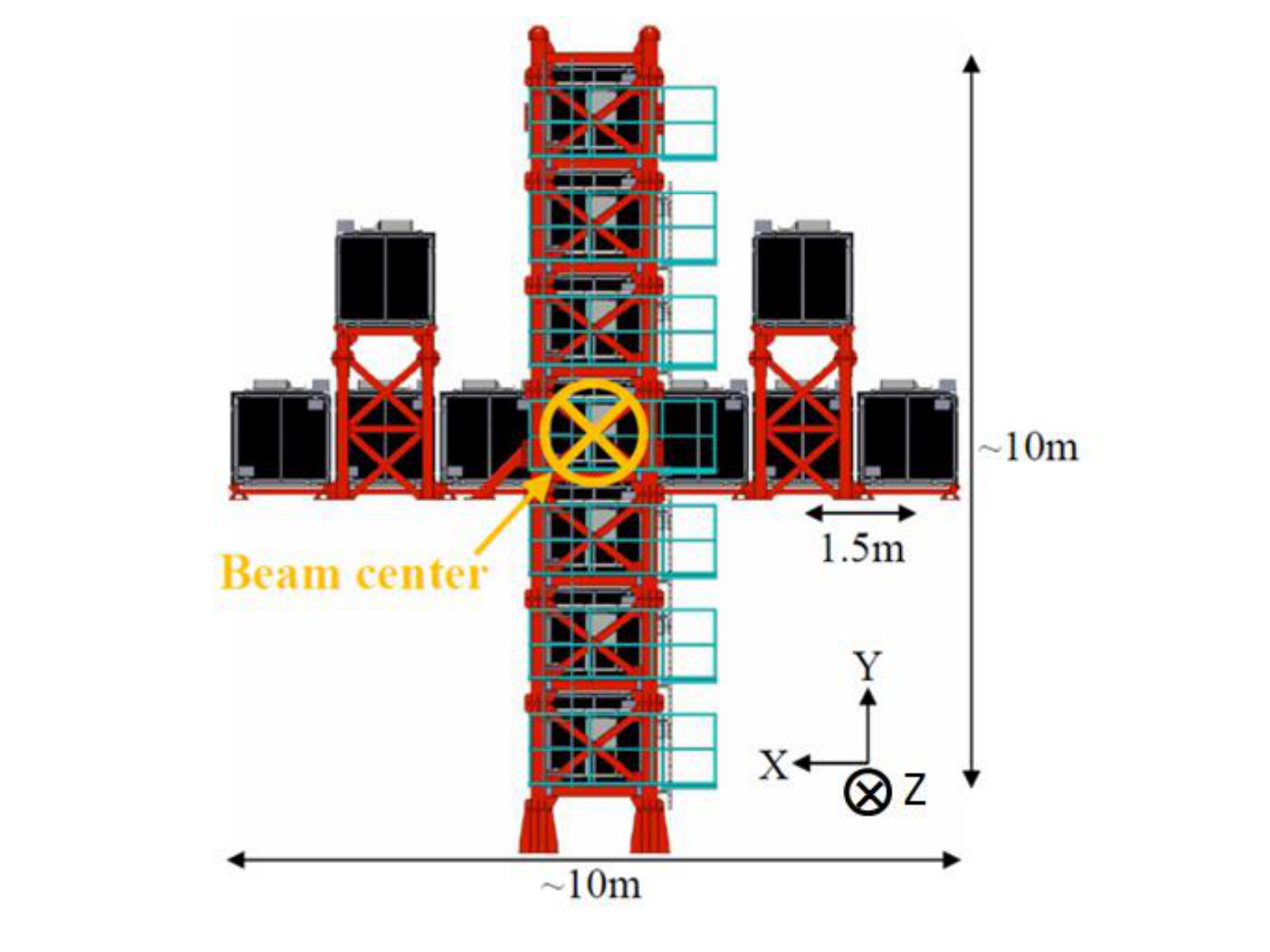 Figure 1
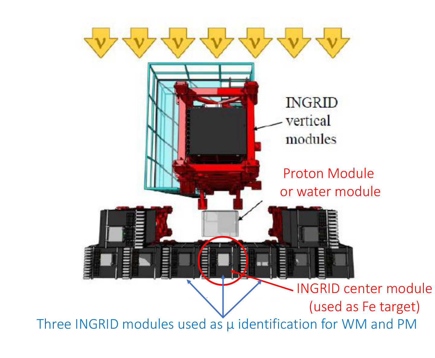 Figure 2
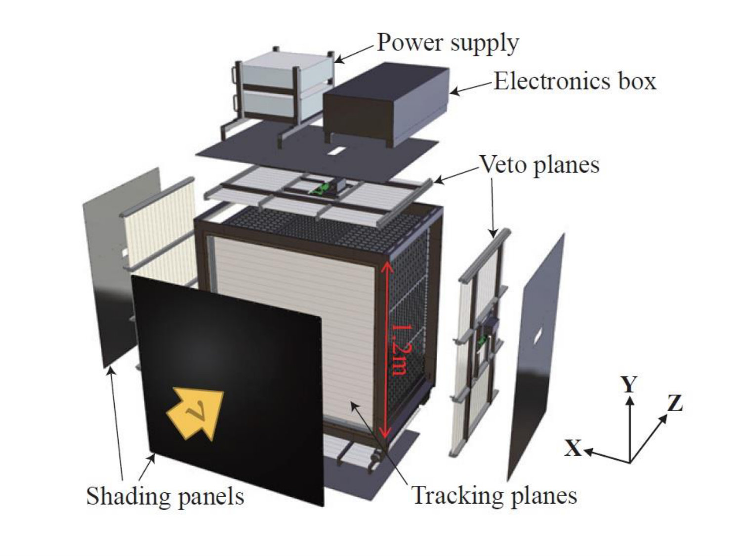 Figure 3
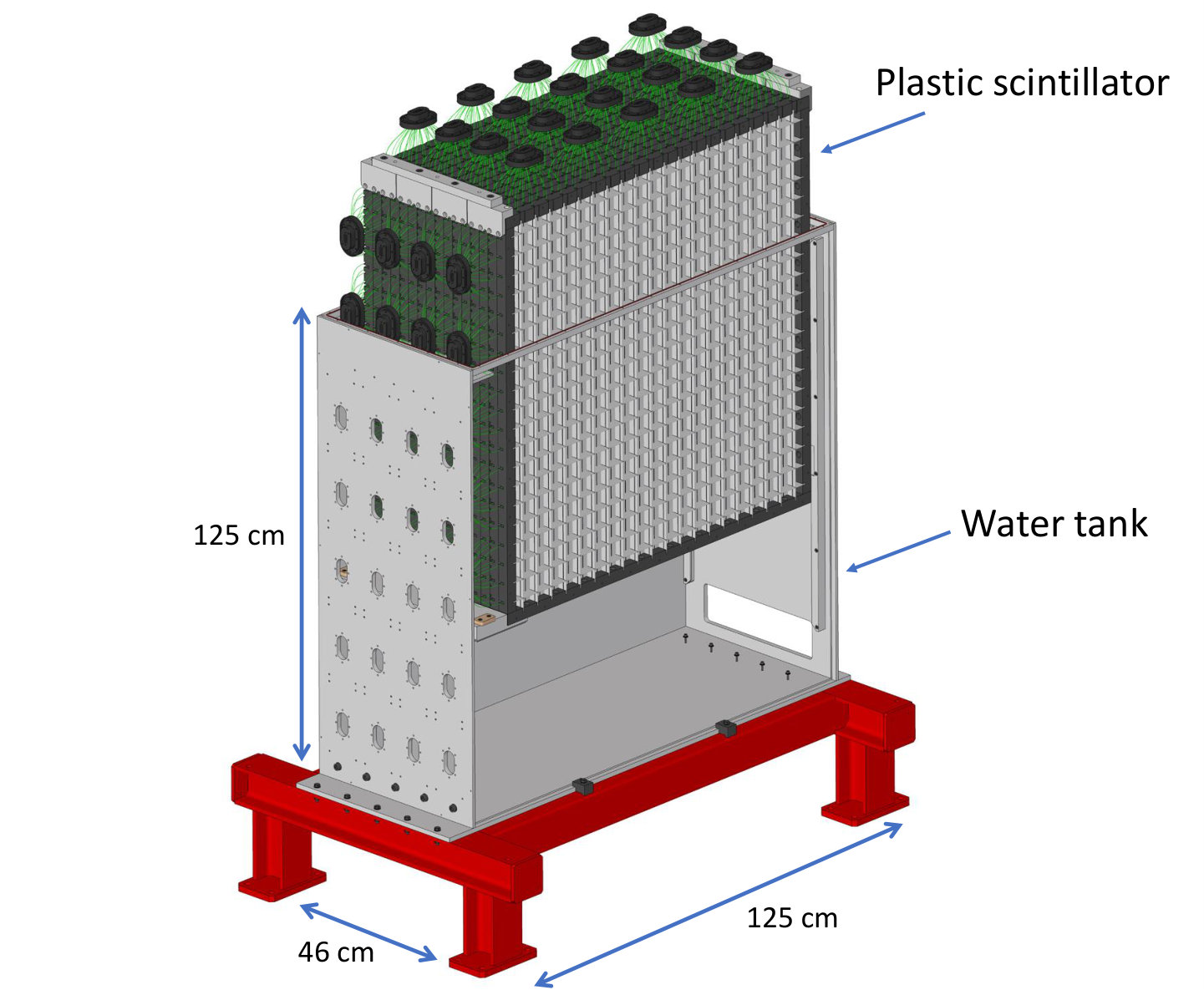 Figure 4
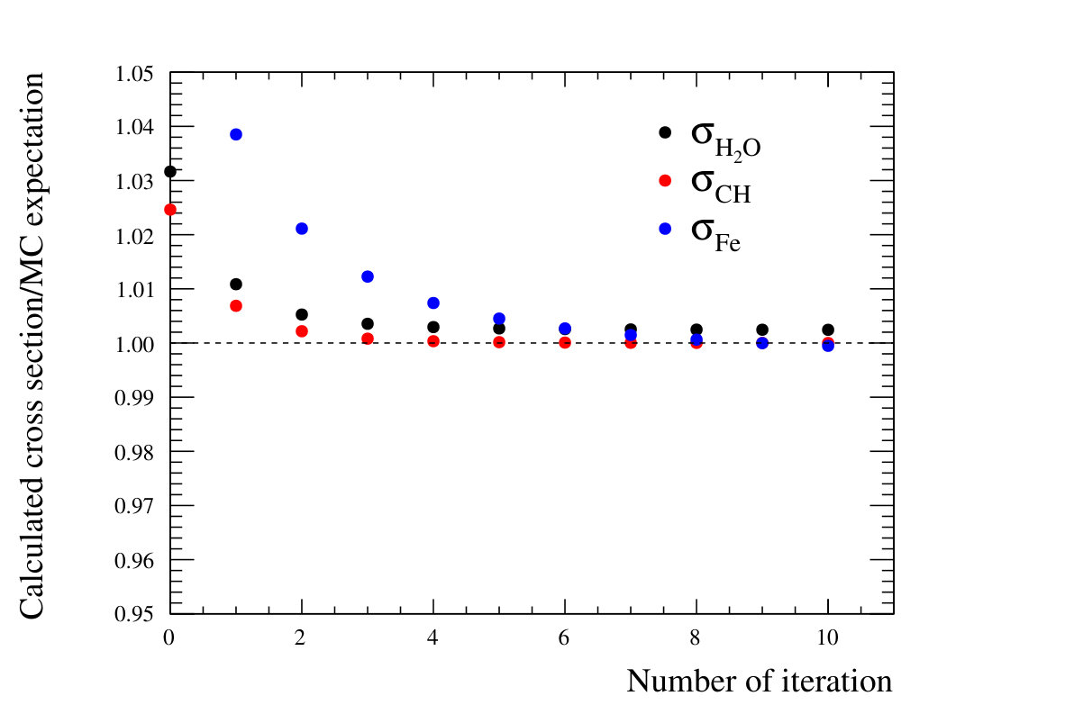 Figure 5
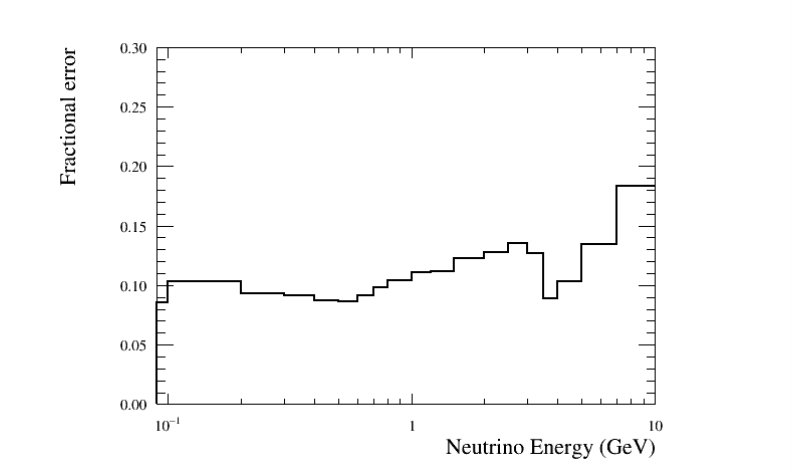 Figure 6
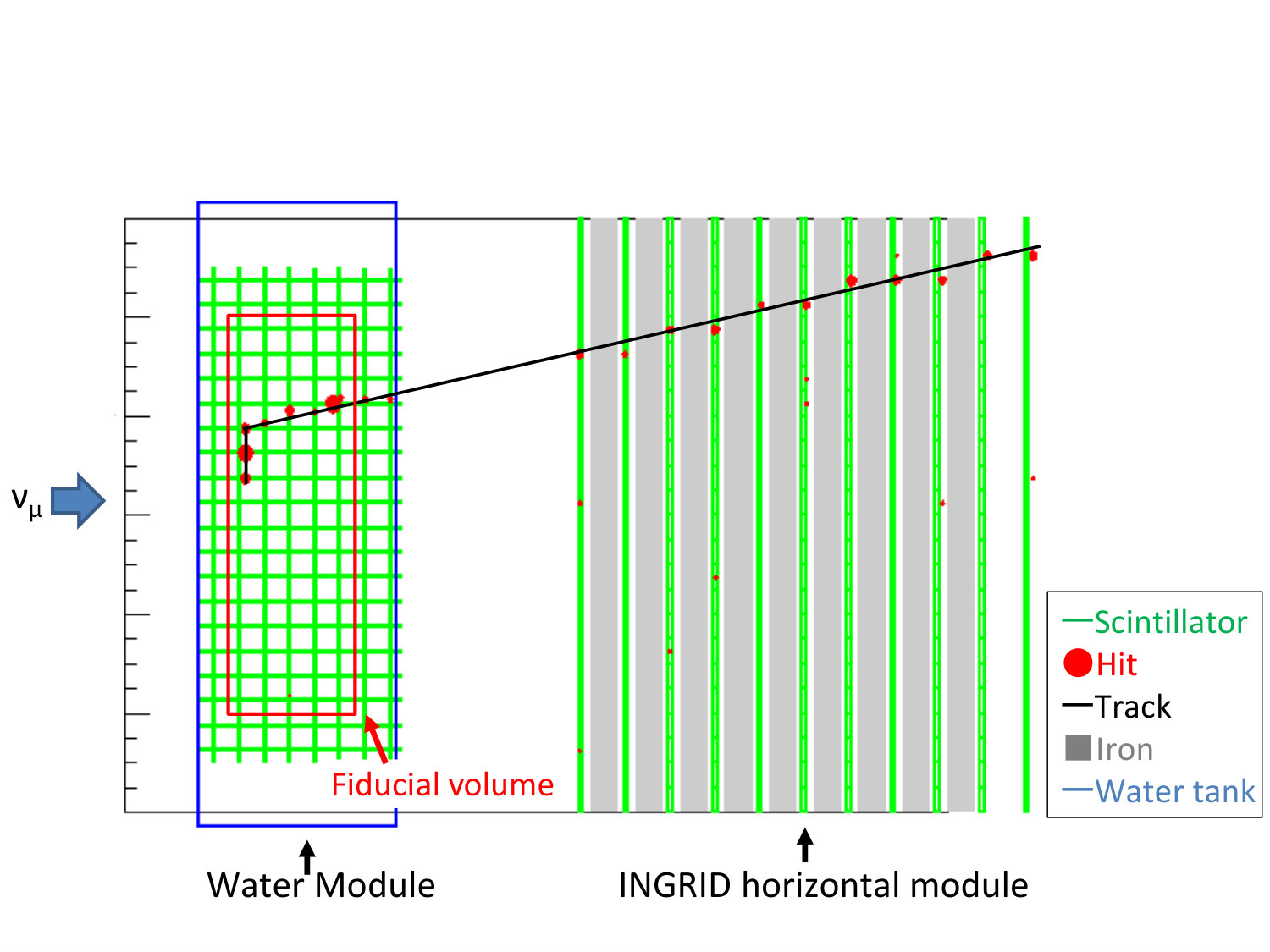 Figure 7
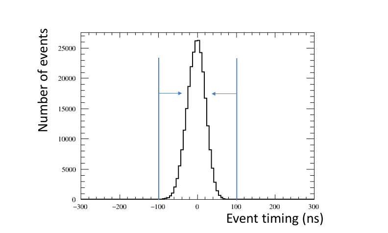 Figure 8
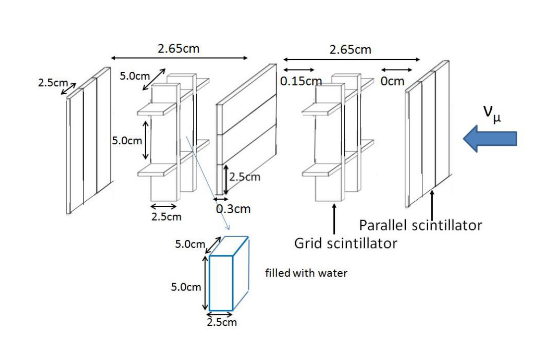 Figure 3
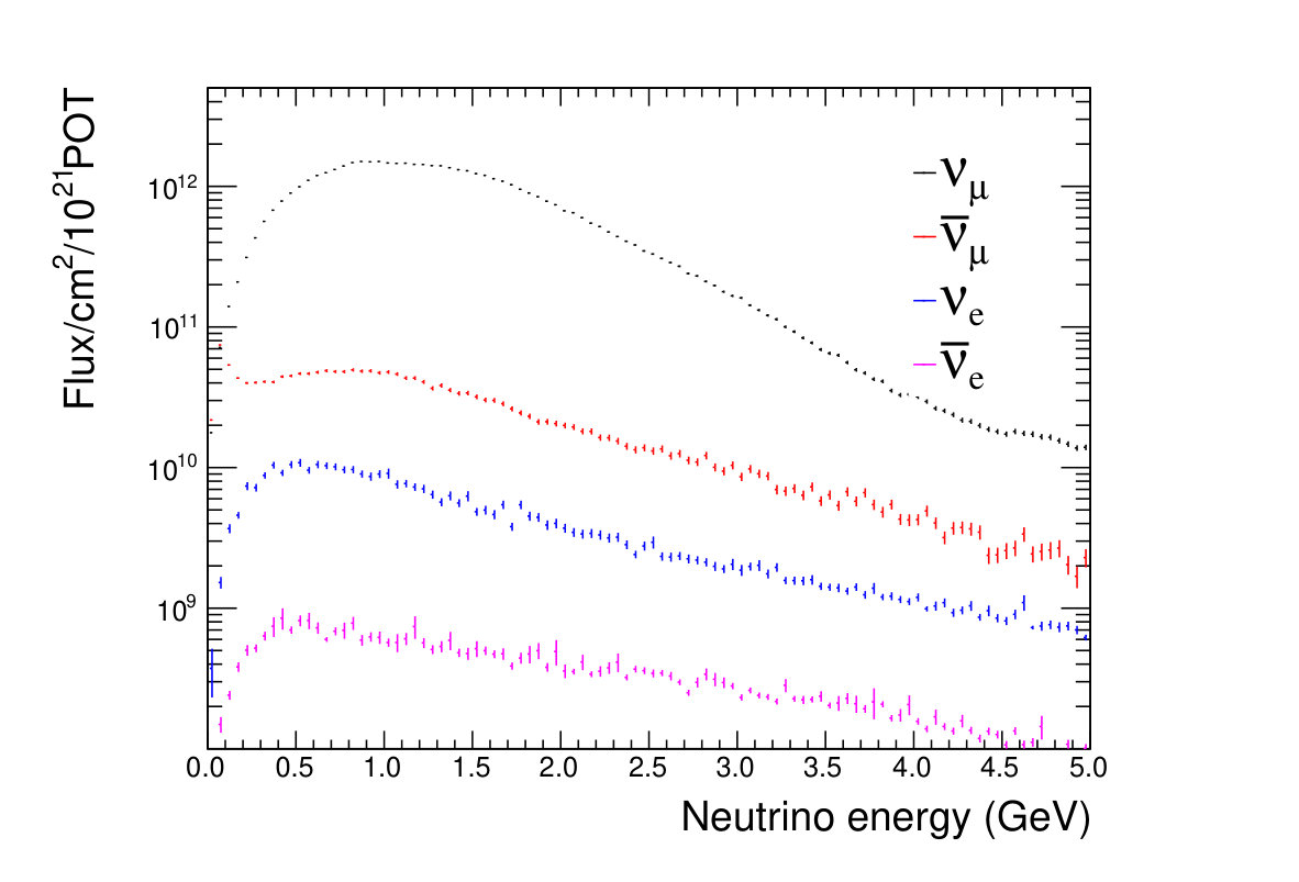 Figure 10
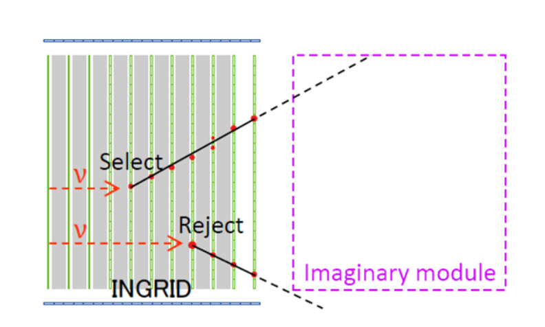 Figure 11
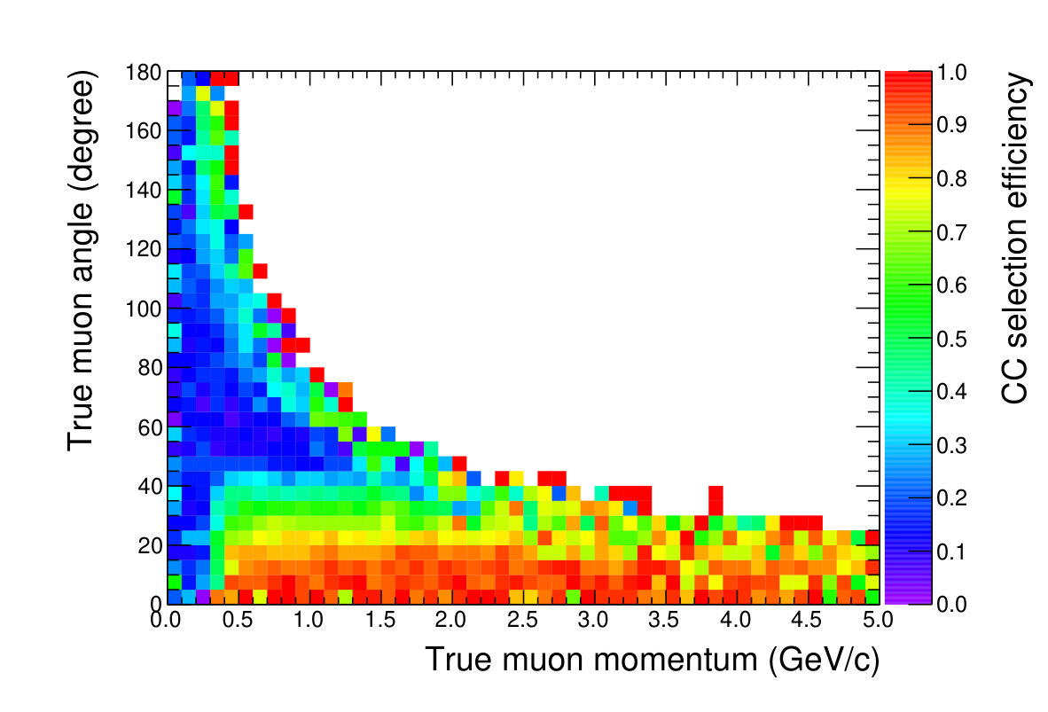 Figure 12
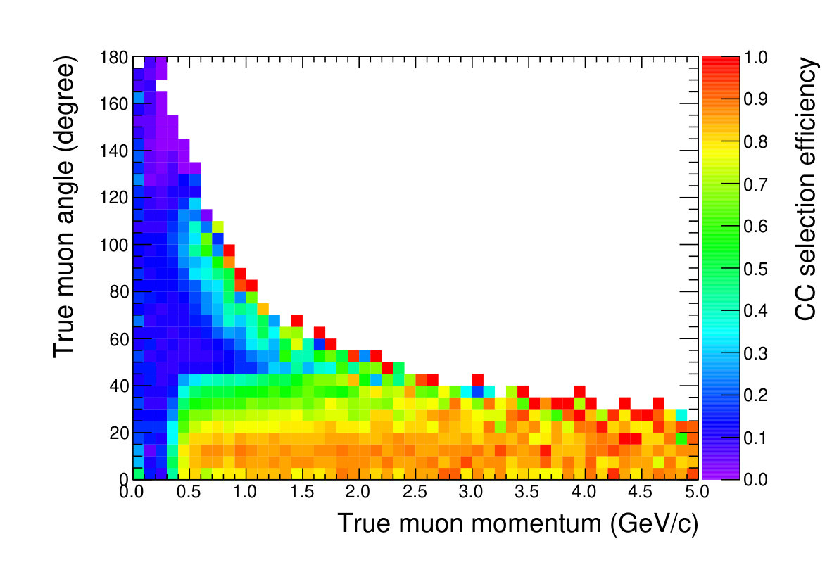 Figure 13
 Figure 14
 Figure 15
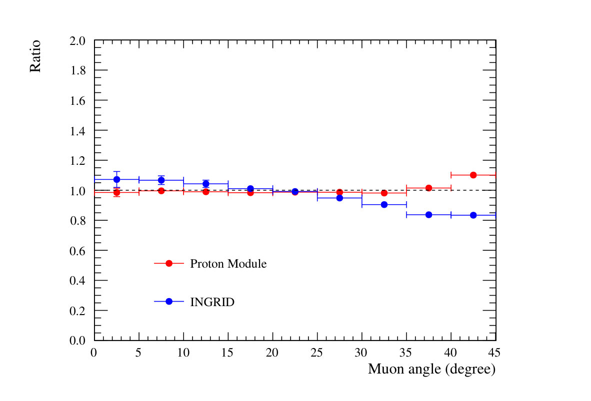 Figure 16
 Figure 17
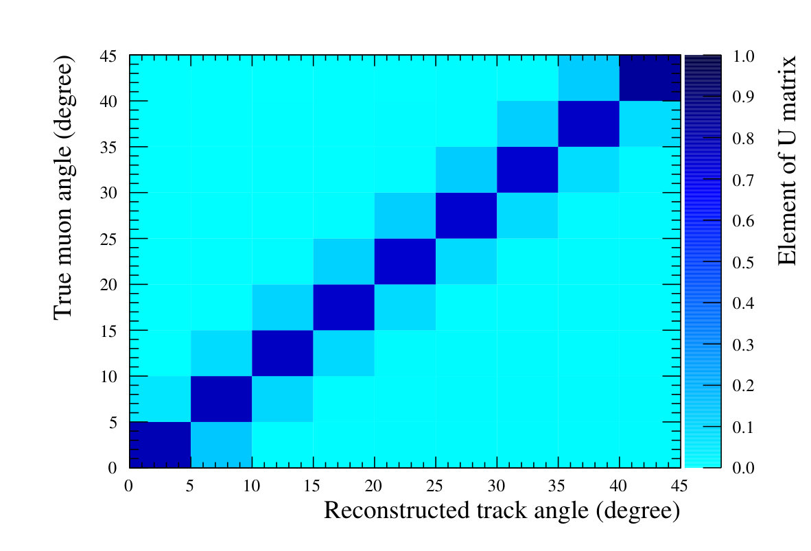 Figure 18
 Figure 19
 Figure 20
 Figure 21
 Figure 22
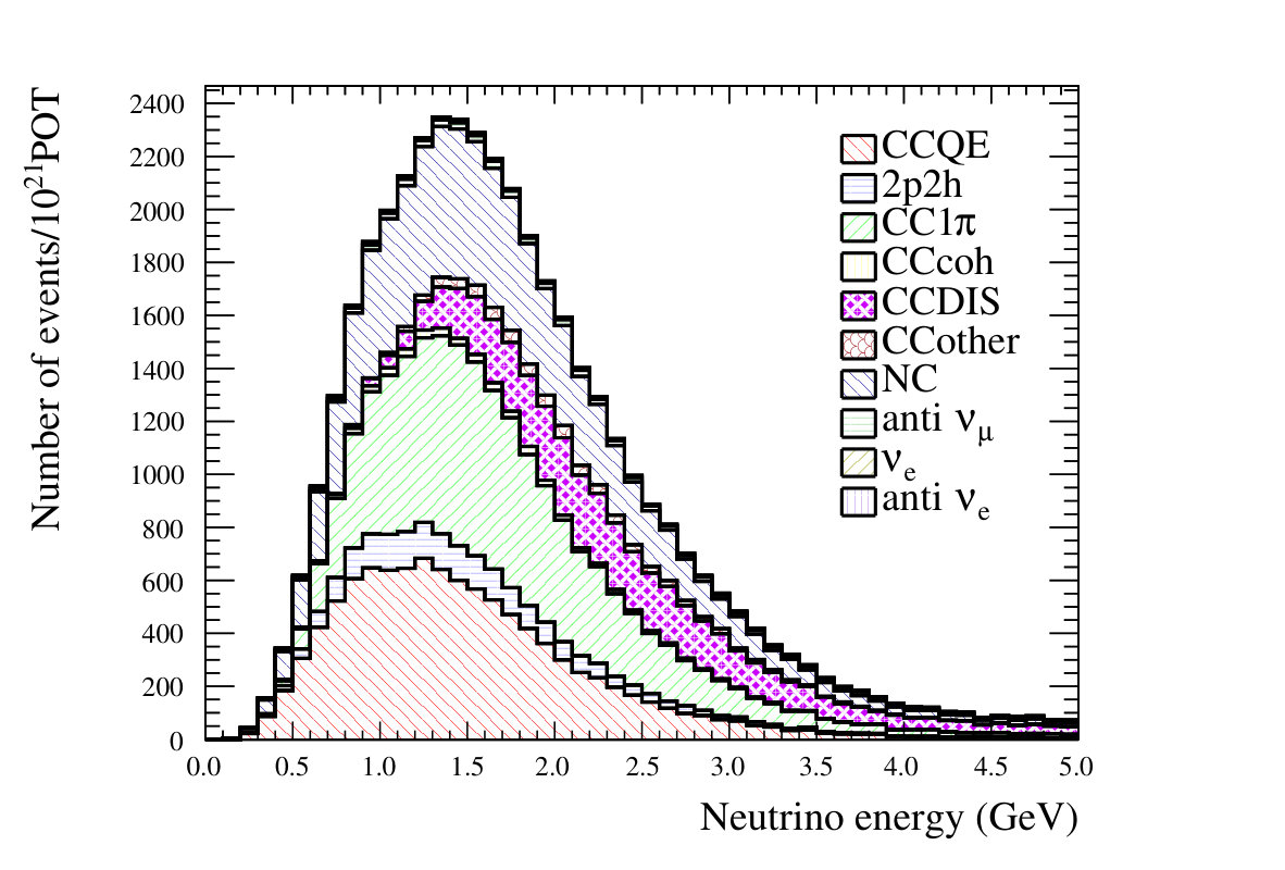 Figure 23
 Figure 24
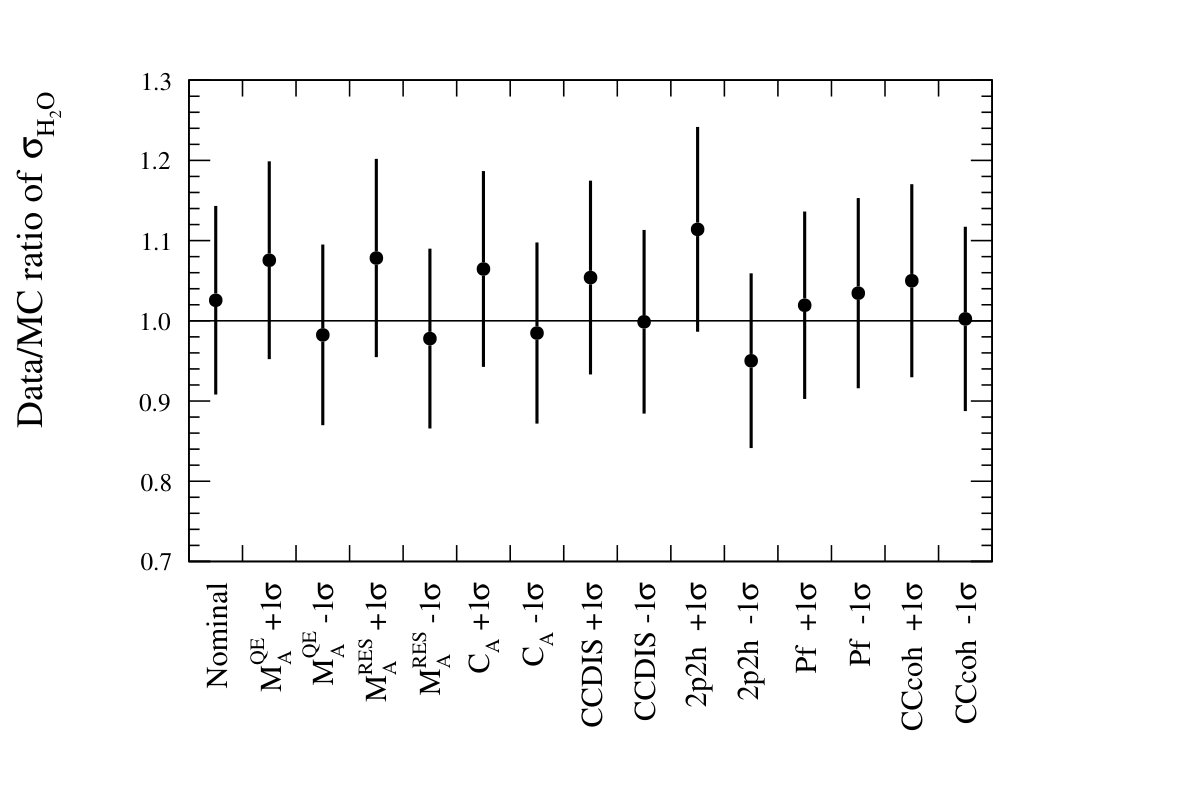 Figure 25
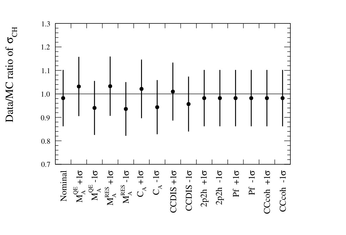 Figure 26
 Figure 27
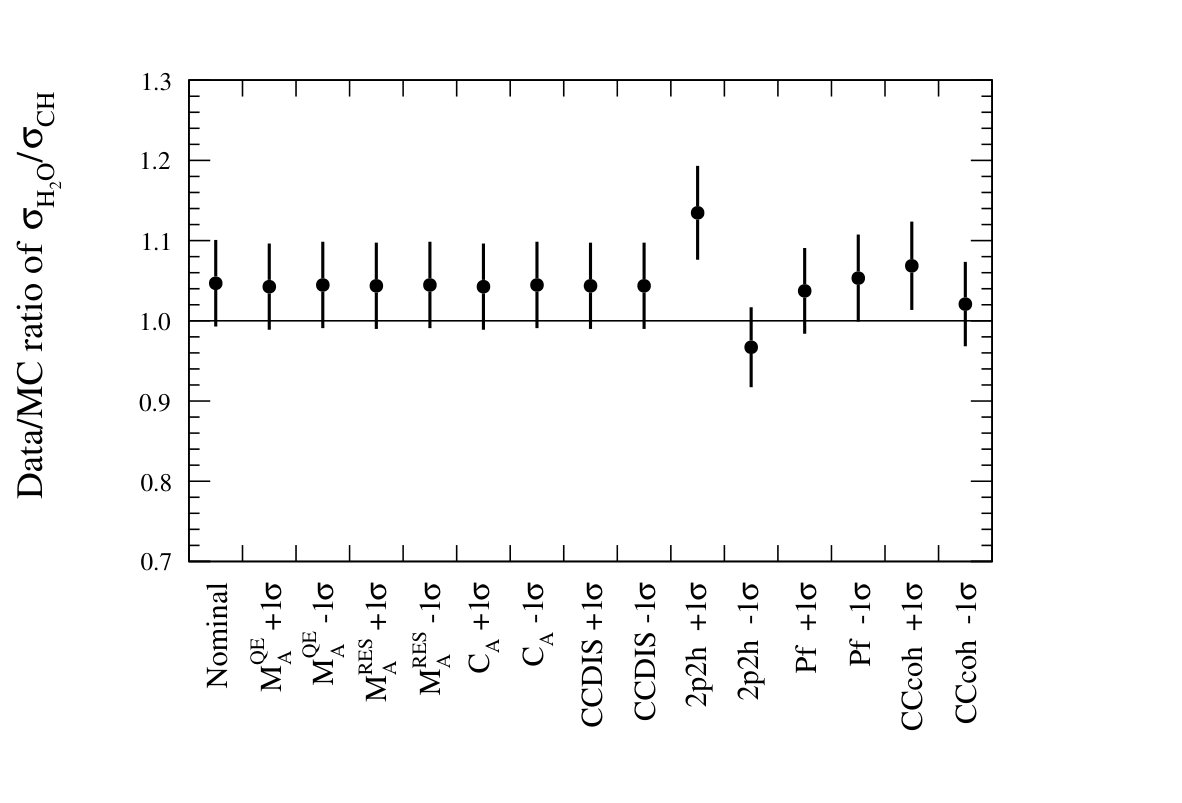 Figure 28
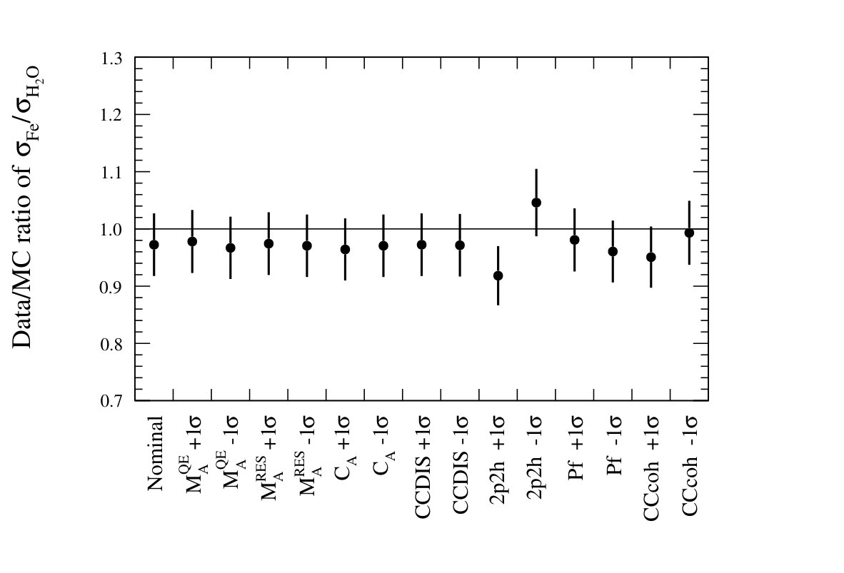 Figure 29
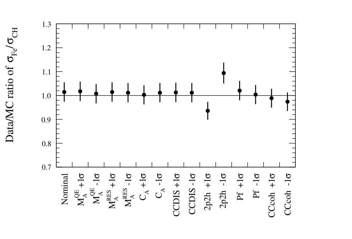 Figure 30
 Figure 31
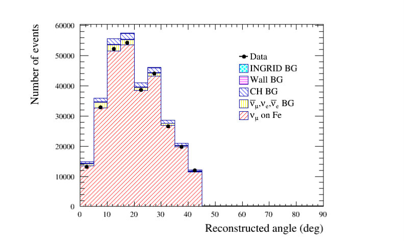 Figure 32
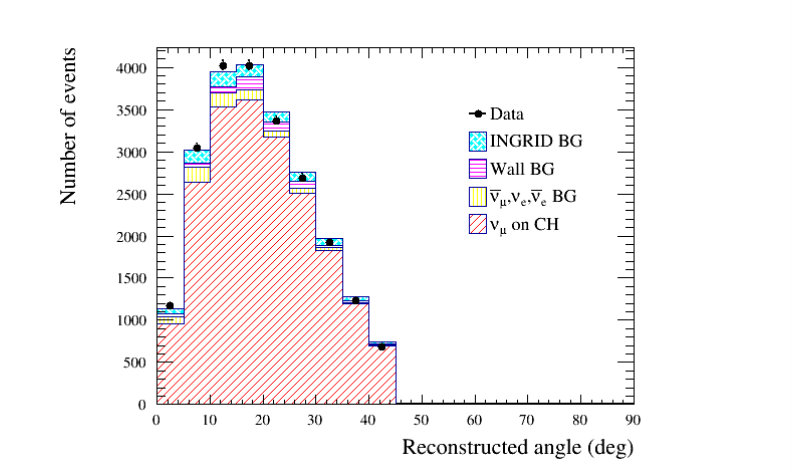 Figure 33
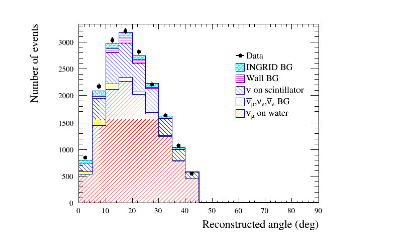 Figure 34
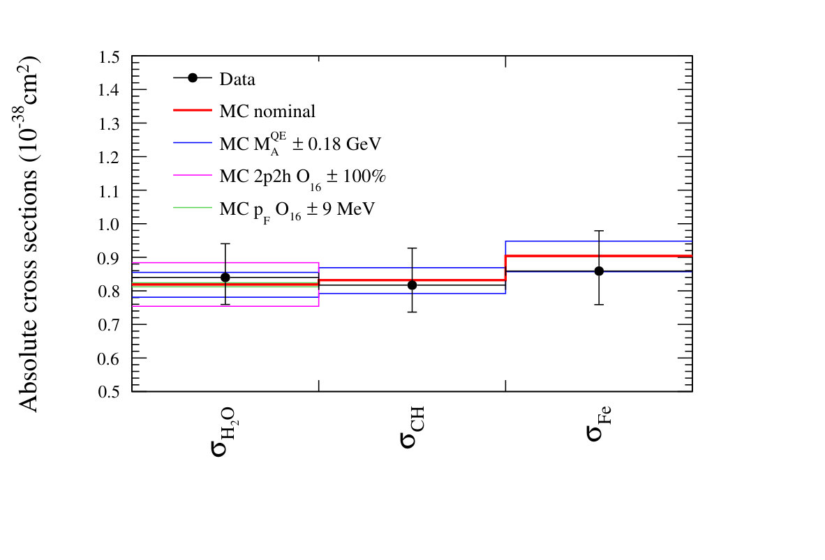 Figure 35
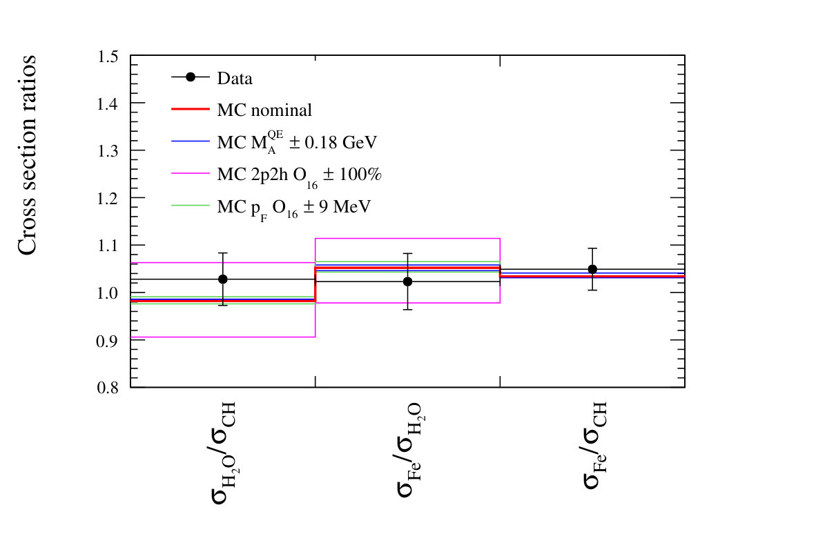 Figure 36
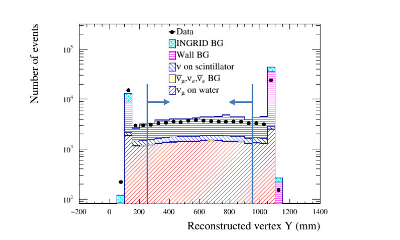 Figure 37
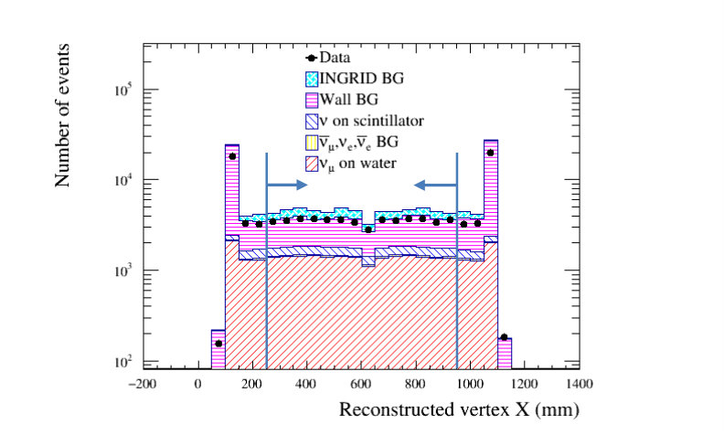 Figure 38
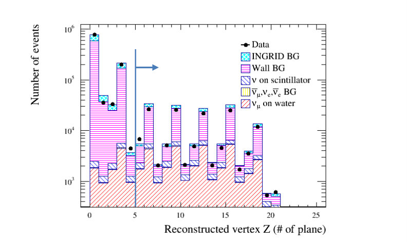 Figure 39
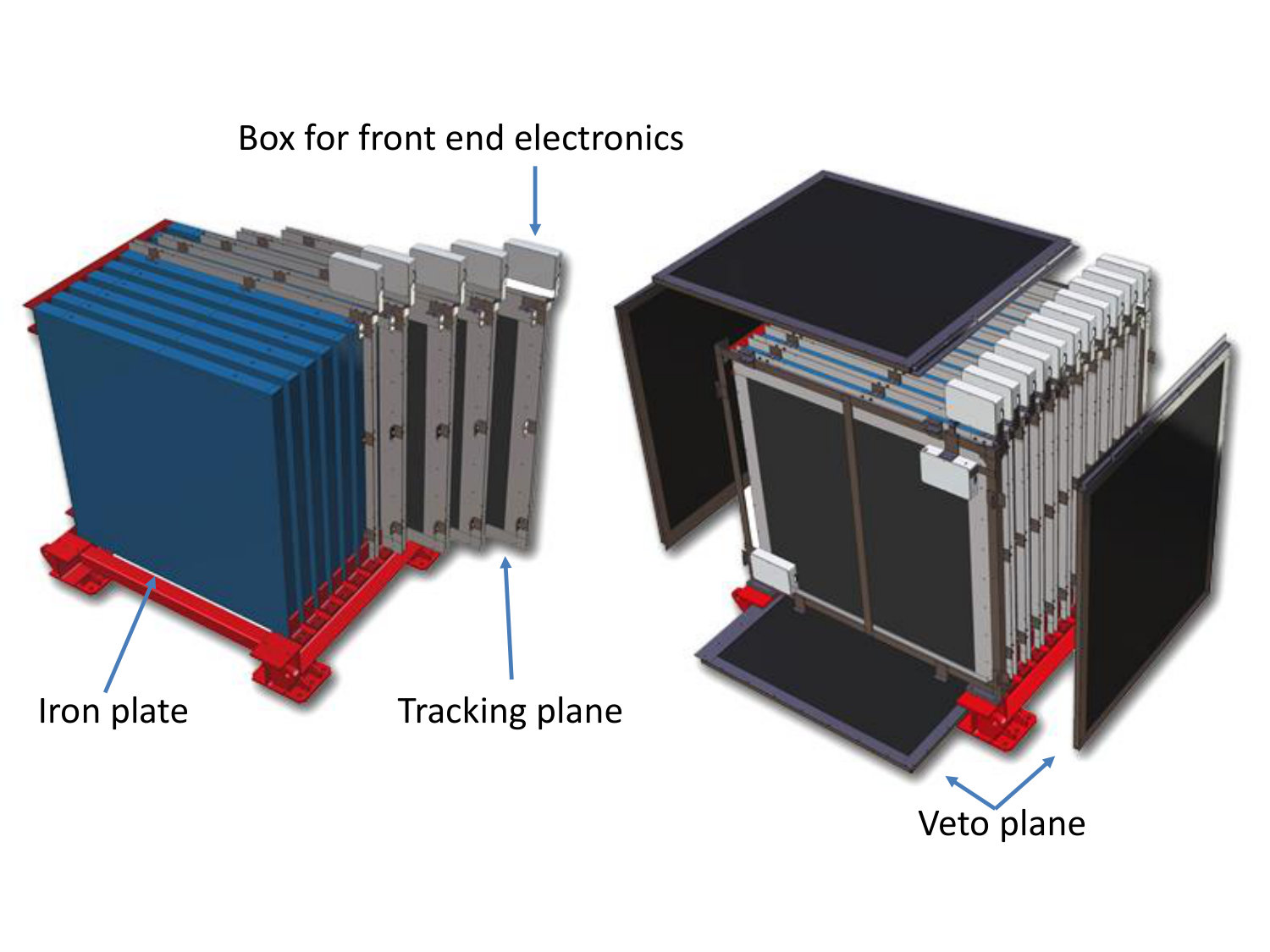 Figure 40
| Parameter | Water Module | Proton Module | INGRID module |
|---|---|---|---|
| Target mass in fiducial volume (ton) | 0.10 | 0.16 | 2.1 |
| Main target materials and fraction | (80%), (19%) | CH (98%) | Fe (96%) |
| Dimension of a scintillator () | 1002.50.3 | 1202.51.3 (SciBar-type), | 12051 |
| 12051 (INGRID-type) | |||
| Dimension of an iron plane () | - | - | 1241246.5 |
| The number of readout channels | 1280 | 1204 | 616 |
| MPPC serial number | S13660 | S10362-13-050C | S10362-13-050C |
| MPPC gain stability | 10% | 10% | 10% |
| MPPC dark noise rate (hits/module/bunch) | 0.2 | 12 | 6 |
| Mean scintillator light yield for MIP | 16 | 56 (SciBar-type), | 23 |
| (p.e. per scintillator thickness) | 23 (INGRID-type) | ||
| Angular acceptance respect to beam axis | 0∘ to 90∘ | 0∘ to 75∘ | 0∘ to 60∘ |
| Period located at on-axis position | July 2016- | November 2010-May 2016 | 2009- |
| Mode | Nominal model | Parameter |
| CCQE-like | Dipole type axial form factor | GeV/. |
| RFG model by Smith-Moniz cite:rfg | = 25, 27, 33 MeV and | |
| with binding energy () and Fermi surface momentum () | = 217, 225, 250 MeV/c for | |
| 12C , 16O, and 56Fe, respectively. | ||
| RPA model by Nieves et al. cite:rpa | RPA is applied for 12O and 16C. | |
| RPA is not applied for 56Fe. | ||
| 2p2h model by Nieves et al. cite:mecnieves | Normalization | |
| 1 | Model by Rein-Sehgal cite:reinsehgal | , |
| GeV/, | ||
| . | ||
| DIS | PYTHIA cite:pytia , Parton distribution function by | Energy dependent normalization |
| GRV98 with Bodek and Yang correction Gluck:1998xa Bodek:2003wc Bodek:2004pc | ||
| Coherent | Model by Berger-Sehgal cite:cccohbarbarseghal | Normalization |
| Cross section | NEUT expectation with RPA | NEUT expectation without RPA |
|---|---|---|
| not available | ||
| 0.984 | 0.983 | |
| not available | 1.051 | |
| not available | 1.033 |
| Water Module | Proton Module | INGRID module | |
|---|---|---|---|
| Time clustering | 50 nsec | 50 nsec | 50 nsec |
| Track matching with INGRID | 35∘ | 35∘ | - |
| 150 mm | 150 mm | - | |
| 3D track matching | 1 parallel plane | 1 plane | 1 plane |
| Vertexing | 3 planes | 2 planes | 2 planes |
| 150 mm | 150 mm | 150 mm | |
| Beam timing | 100 nsec | 100 nsec | 100 nsec |
| Upstream veto | second parallel plane | second plane | first plane |
| Fiducial | 700 mm700 mm | 700 mm700 mm | 700 mm700 mm |
| Reconstructed angle | 45∘ | 45∘ | 45∘ |
| Selection | Data | MC | |||||||
|---|---|---|---|---|---|---|---|---|---|
| CC | NC | , , | CH B.G. | Wall B.G. | INGRID B.G. | All | |||
| Vertexing cut | 1175980 | (4%) | 1.66 | ||||||
| Front veto cut | 100790 | (21%) | 1.04 | ||||||
| Fiducial cut | 17992 | (69%) | 4.68 | ||||||
| Track angle cut | 17528 | (69%) | 4.53 |
| Selection | Data | MC | ||||||
|---|---|---|---|---|---|---|---|---|
| CC | NC | , , | Wall B.G. | INGRID B.G. | All | |||
| Vertexing cut | 1321290 | (4%) | 2.66 | |||||
| Front veto cut | 264550 | (15%) | 2.25 | |||||
| Fiducial cut | 22930 | (85%) | 9.52 | |||||
| Track angle cut | 22165 | (85%) | 9.14 |
| Selection | Data | MC | ||||||
|---|---|---|---|---|---|---|---|---|
| CC | NC | , , | CH B.G. | Wall B.G. | INGRID B.G. | All | ||
| Vertexing cut | 3019430 | (44%) | ||||||
| Front veto cut | 1468490 | (74%) | ||||||
| Fiducial cut | 431211 | (88%) | ||||||
| Acceptance cut | 308971 | (88%) | ||||||
| Track angle cut | 293418 | (88%) |
| reconstructed angle bin | |||
|---|---|---|---|
| 0-5∘ | 13106 | 13582.0 | 1.036 |
| 5-10∘ | 32928 | 33765.3 | 1.025 |
| 10-15∘ | 52272 | 53671.3 | 1.027 |
| 15-20∘ | 54205 | 55500.6 | 1.024 |
| 20-25∘ | 38540 | 39119.4 | 1.015 |
| 25-30∘ | 44097 | 45002.4 | 1.021 |
| 30-35∘ | 26615 | 26984.1 | 1.014 |
| 35-40∘ | 19709 | 20036.4 | 1.017 |
| 40-45∘ | 11946 | 12094.0 | 1.012 |
| Total | 293418 | 299755.5 | 1.022 |
| Detector | angle bin | CC out of | Non-target | NC | , , | Wall | INGRID | All BG |
| phase space | element | |||||||
| Water | 0-5∘ | 44.5 | 26.1 | 28.6 | 43.5 | 4.90 | 55.2 | 216 |
| Module | 5-10∘ | 98.2 | 55.1 | 67.4 | 99.2 | 36.7 | 96.6 | 477 |
| 10-15∘ | 145 | 72.0 | 83.7 | 103 | 73.8 | 10.3 | 615 | |
| 15-20∘ | 171 | 76.3 | 86.4 | 75.6 | 113 | 90.0 | 654 | |
| 20-25∘ | 165 | 58.2 | 76.7 | 51.7 | 58.9 | 77.2 | 527 | |
| 25-30∘ | 113 | 43.6 | 54.8 | 30.9 | 32.7 | 72.9 | 377 | |
| 30-35∘ | 84.4 | 27.6 | 32.4 | 19.6 | 13.2 | 33.4 | 229 | |
| 35-40∘ | 35.0 | 15.6 | 16.3 | 10.9 | 12.4 | 25.8 | 126 | |
| 40-45∘ | 40.2 | 7.70 | 6.99 | 4.72 | 1.24 | 9.74 | 82.4 | |
| Total | 896 | 382 | 453 | 439 | 3.47 | 564 | 3300 | |
| Proton | 0-5∘ | 99.0 | 12.9 | 60.3 | 79.7 | 38.2 | 57.2 | 346 |
| Module | 5-10∘ | 255 | 35.7 | 145 | 172 | 47.4 | 154 | 905 |
| 10-15∘ | 338 | 48.0 | 174 | 162 | 75.2 | 183 | 975 | |
| 15-20∘ | 352 | 49.1 | 177 | 129 | 145 | 150 | 997 | |
| 20-25∘ | 313 | 43.3 | 144 | 78.8 | 104 | 124 | 803 | |
| 25-30∘ | 243 | 34.5 | 101 | 50.6 | 83.7 | 107 | 616 | |
| 30-35∘ | 148 | 25.3 | 63.4 | 30.1 | 23.9 | 90.4 | 379 | |
| 35-40∘ | 67.6 | 16.6 | 32.4 | 15.2 | 20.5 | 56.1 | 207 | |
| 40-45∘ | 83.5 | 9.69 | 17.3 | 8.96 | 12.4 | 28.3 | 159 | |
| Total | 1870 | 275 | 914 | 726 | 551 | 950 | 5290 | |
| INGRID | 0-5∘ | 1370 | 507 | 769 | 766 | 95.7 | 7.96 | 3540 |
| module | 5-10∘ | 2910 | 1310 | 1690 | 1740 | 145 | 101 | 7900 |
| 10-15∘ | 4990 | 1990 | 2680 | 2020 | 147 | 122 | 11900 | |
| 15-20∘ | 5630 | 2020 | 3280 | 1720 | 114 | 216 | 13000 | |
| 20-25∘ | 3990 | 1440 | 2100 | 1010 | 109 | 49.0 | 8690 | |
| 25-30∘ | 5520 | 1680 | 3070 | 993 | 126 | 88.8 | 11500 | |
| 30-35∘ | 3320 | 997 | 1660 | 588 | 58.0 | 19.7 | 6650 | |
| 35-40∘ | 3650 | 702 | 1170 | 338 | 34.9 | 19.2 | 5920 | |
| 40-45∘ | 3080 | 456 | 801 | 144 | 40.2 | 13.2 | 4530 | |
| Total | 34500 | 11100 | 17200 | 9310 | 870 | 638 | 73600 |
| Water Module | Proton Module | INGRID module | |
|---|---|---|---|
| Integrated flux per POT () | |||
| Used POT in this analysis | |||
| Integrated flux per used POT () |
| Number of target nucleons | |
|---|---|
| Target | Calculated cross sections | Expected cross sections |
|---|---|---|
| CH | ||
| Fe |
| Systematic uncertainty | ||||||
|---|---|---|---|---|---|---|
| Flux-related | ||||||
| (hadron production and beam line) | ||||||
| Flux-related | – | – | ||||
| (difference of running periods and location) | – | – | ||||
| Interaction model-related | ||||||
| Detector response-related | ||||||
| Total | ||||||
| Parameter | Nominal value | Uncertainties (1) |
| CCQE-like | ||
| 1.15 GeV/ | 0.18 GeV/ | |
| 217 MeV/c | 31 MeV/c | |
| 225 MeV/c | 31 MeV/c | |
| 250 MeV/c | 35 MeV/c | |
| 25 MeV/c | 9 MeV/c | |
| 27 MeV/c | 9 MeV/c | |
| 33 MeV/c | 11 MeV/c | |
| 100% | 100% | |
| 100% | 100% | |
| 100% | 100% | |
| 1 | ||
| 1.01 | 0.12 | |
| 0.95 GeV/ | 0.15 GeV/ | |
| 1.30 | 0.20 | |
| CC multi-pion and DIS production | ||
| Normalization uncertainty is applied depending on neutrino energy by 0.4/ (GeV) | ||
| CC coherent | ||
| 100% | 30% | |
| 100% | 30% | |
| Normalization of NC interactions | ||
| 100% | 30% | |
| NC multi-pion and DIS production normalization | 100% | 30% |
| Secondary interaction of pions | ||
| Pion absorption normalization | 100% | 50% |
| Pion charge exchange normalization (500 MeV/) | 100% | 50% |
| Pion charge exchange normalization (500 MeV/) | 100% | 30% |
| Pion quasi elastic normalization (500 MeV/) | 100% | 50% |
| Pion quasi elastic normalization (500 MeV/) | 100% | 30% |
| Pion inelastic normalization | 100% | 50% |
| Parameter | ||||||
|---|---|---|---|---|---|---|
| 1.1 | 1.2 | 1.6 | 0.1 | 0.5 | 0.5 | |
| 0.6 | 1.2 | 2.0 | 0.5 | 1.5 | 1.0 | |
| 0.1 | 0.3 | 1.0 | 0.3 | 1.0 | 0.7 | |
| 0.1 | 0.2 | 0.6 | 0.2 | 0.5 | 0.3 | |
| CC multi-pion and DIS production | 0.2 | 0.7 | 1.3 | 0.5 | 1.1 | 0.6 |
| NC multi-pion and DIS production | 0.8 | 1.1 | 1.7 | 0.3 | 0.9 | 0.6 |
| 0.1 | 0.4 | 0.3 | 0.4 | 0.3 | 0.4 | |
| 0.2 | 0 | 0 | 0.2 | 0.2 | 0 | |
| 0 | 0 | 0.4 | 0 | 0.4 | 0.4 | |
| Pion absorption normalization | 0.2 | 0.1 | 0.2 | 0.2 | 0.4 | 0.2 |
| Pion quasi elastic normalization (500 MeV/) | 0.2 | 0.1 | 0.1 | 0.2 | 0.4 | 0.4 |
| Pion quasi elastic normalization (500 MeV/) | 0.2 | 0.1 | 0.3 | 0.1 | 0.1 | 0.1 |
| Pion inelastic normalization | 0.2 | 0.2 | 0.3 | 0.1 | 0.1 | 0.2 |
| Backscattered protons and pions | 1.5 | 0.8 | 1.0 | 1.8 | 1.8 | 1.3 |
| 2.6 | 3.1 | 5.2 | 2.3 | 4.0 | 2.7 |
| cross section | ||||
|---|---|---|---|---|
| Detector | Water Module | Proton Module | Proton Module | INGRID |
| Target mass | 0.68 | 0.05 | 0.27 | 0.14 |
| MPPC noise | 0.01 | 0.09 | 0.39 | 0.09 |
| Scintillator crosstalk | 0.30 | – | – | – |
| Hit efficiency | 0.27 | 0.02 | 0.50 | 0.94 |
| Event pileup | 0.72 | 0.15 | 0.64 | 0.09 |
| Beam-related background | 1.09 | 0.31 | 1.31 | 0.38 |
| Non-beam-related background | 0.04 | 0.02 | 0.02 | 0.01 |
| 2D Track reconstruction | 0.60 | 0.28 | 1.18 | 0.43 |
| Track matching with INGRID | 1.42 | 0.20 | 0.84 | – |
| 3D track matching | 0.89 | 0.13 | 0.56 | 0.35 |
| Vertexing | 0.44 | 0.05 | 0.20 | 0.28 |
| Beam timing cut | 0.06 | 0.01 | 0.01 | 0.01 |
| VETO and FV cut | 1.19 | 0.18 | 0.72 | 0.52 |
| Acceptance cut | – | – | – | 0.61 |
| Total | 2.88 | 2.52 | 1.54 | |
| Parameter | ||||||
|---|---|---|---|---|---|---|
| Nominal for | 0.819 | 0.832 | - | 0.985 | - | - |
| (RPA+RFG+MEC) | ||||||
| Nominal for | 0.860 | 0.875 | 0.904 | 0.982 | 1.052 | 1.034 |
| (RFG+MEC) | ||||||
| 0.781 | 0.792 | 0.857 | 0.986 | 1.046 | 1.031 | |
| 0.855 | 0.869 | 0.948 | 0.984 | 1.058 | 1.041 | |
| 0.779 | 0.791 | 0.861 | 0.985 | 1.050 | 1.034 | |
| 0.859 | 0.873 | 0.948 | 0.984 | 1.054 | 1.037 | |
| 0.789 | 0.800 | 0.871 | 0.986 | 1.061 | 1.046 | |
| 0.853 | 0.866 | 0.941 | 0.984 | 1.054 | 1.037 | |
| 0.806 | 0.818 | 0.889 | 0.985 | 1.051 | 1.035 | |
| 0.835 | 0.848 | 0.923 | 0.985 | 1.053 | 1.037 | |
| 0.797 | 0.809 | 0.880 | 0.985 | 1.052 | 1.036 | |
| 0.841 | 0.854 | 0.928 | 0.985 | 1.053 | 1.037 | |
| 0.819 | 0.835 | 0.904 | 0.981 | 1.052 | 1.028 | |
| 0.819 | 0.825 | 0.904 | 0.993 | 1.052 | 1.045 | |
| 0.824 | 0.832 | 0.904 | 0.991 | 1.043 | 1.034 | |
| 0.812 | 0.832 | 0.904 | 0.976 | 1.065 | 1.034 | |
| 0.819 | 0.831 | 0.904 | 0.986 | 1.052 | 1.035 | |
| 0.819 | 0.833 | 0.904 | 0.984 | 1.052 | 1.032 | |
| 0.818 | 0.832 | 0.904 | 0.984 | 1.054 | 1.034 | |
| 0.820 | 0.832 | 0.904 | 0.986 | 1.051 | 1.034 | |
| 0.819 | 0.764 | 0.904 | 1.072 | 1.052 | 1.121 | |
| 0.819 | 0.900 | 0.904 | 0.910 | 1.052 | 0.959 | |
| 0.754 | 0.832 | 0.904 | 0.906 | 1.139 | 1.034 | |
| 0.884 | 0.832 | 0.904 | 1.063 | 0.978 | 1.034 | |
| 0.819 | 0.809 | 0.904 | 1.013 | 1.052 | 1.061 | |
| 0.819 | 0.855 | 0.904 | 0.958 | 1.052 | 1.007 | |
| 0.800 | 0.832 | 0.904 | 0.962 | 1.076 | 1.034 | |
| 0.838 | 0.832 | 0.904 | 1.007 | 1.030 | 1.034 | |
| 0.819 | 0.832 | 0.896 | 0.958 | 1.043 | 1.023 | |
| 0.819 | 0.832 | 0.913 | 0.958 | 1.062 | 1.044 |
Peer Reviews
No public reviews on file for this paper yet. If you reviewed it on a platform where reviews are public (OpenReview, ICLR, NeurIPS, ICML), you can paste yours below so the community can read it here.
Videos
No videos yet. Explain this paper in a talk, walkthrough, or lecture? Add one.
\preprintnumber
XXXX-XXXX
Measurement of the charged-current cross sections on water, hydrocarbon, iron, and their ratios with the T2K on-axis detectors
K. Abe
University Autonoma Madrid, Department of Theoretical Physics, 28049 Madrid, Spain
R. Akutsu
University of Bern, Albert Einstein Center for Fundamental Physics, Laboratory for High Energy Physics (LHEP), Bern, Switzerland
A. Ali
Boston University, Department of Physics, Boston, Massachusetts, U.S.A.
C. Andreopoulos
University of British Columbia, Department of Physics and Astronomy, Vancouver, British Columbia, Canada
L. Anthony
University of California, Irvine, Department of Physics and Astronomy, Irvine, California, U.S.A.
M. Antonova
IRFU, CEA Saclay, Gif-sur-Yvette, France
S. Aoki
University of Colorado at Boulder, Department of Physics, Boulder, Colorado, U.S.A.
A. Ariga
Colorado State University, Department of Physics, Fort Collins, Colorado, U.S.A.
Y. Ashida
Duke University, Department of Physics, Durham, North Carolina, U.S.A.
Y. Awataguchi
Ecole Polytechnique, IN2P3-CNRS, Laboratoire Leprince-Ringuet, Palaiseau, France
Y. Azuma
ETH Zurich, Institute for Particle Physics, Zurich, Switzerland
S. Ban
University of Geneva, Section de Physique, DPNC, Geneva, Switzerland
M. Barbi
H. Niewodniczanski Institute of Nuclear Physics PAN, Cracow, Poland
G.J. Barker
High Energy Accelerator Research Organization (KEK), Tsukuba, Ibaraki, Japan
G. Barr
University of Houston, Department of Physics, Houston, Texas, U.S.A.
C. Barry
Institut de Fisica d’Altes Energies (IFAE), The Barcelona Institute of Science and Technology, Campus UAB, Bellaterra (Barcelona) Spain
M. Batkiewicz-Kwasniak
IFIC (CSIC & University of Valencia), Valencia, Spain
F. Bench
Institute For Interdisciplinary Research in Science and Education (IFIRSE), ICISE, Quy Nhon, Vietnam
V. Berardi
Imperial College London, Department of Physics, London, United Kingdom
S. Berkman
INFN Sezione di Bari and Università e Politecnico di Bari, Dipartimento Interuniversitario di Fisica, Bari, Italy
R.M. Berner
INFN Sezione di Napoli and Università di Napoli, Dipartimento di Fisica, Napoli, Italy
L. Berns
INFN Sezione di Padova and Università di Padova, Dipartimento di Fisica, Padova, Italy
S. Bhadra
INFN Sezione di Roma and Università di Roma “La Sapienza”, Roma, Italy
S. Bienstock
Institute for Nuclear Research of the Russian Academy of Sciences, Moscow, Russia
A. Blondel now at CERN Institute of Physics (IOP), Vietnam Academy of Science and Technology (VAST), Hanoi, Vietnam
S. Bolognesi
Kavli Institute for the Physics and Mathematics of the Universe (WPI), The University of Tokyo Institutes for Advanced Study, University of Tokyo, Kashiwa, Chiba, Japan
B. Bourguille
Kobe University, Kobe, Japan
S.B. Boyd
Kyoto University, Department of Physics, Kyoto, Japan
D. Brailsford
Lancaster University, Physics Department, Lancaster, United Kingdom
A. Bravar
University of Liverpool, Department of Physics, Liverpool, United Kingdom
C. Bronner
Louisiana State University, Department of Physics and Astronomy, Baton Rouge, Louisiana, U.S.A.
M. Buizza Avanzini
Michigan State University, Department of Physics and Astronomy, East Lansing, Michigan, U.S.A.
J. Calcutt
Miyagi University of Education, Department of Physics, Sendai, Japan
T. Campbell
National Centre for Nuclear Research, Warsaw, Poland
S. Cao
State University of New York at Stony Brook, Department of Physics and Astronomy, Stony Brook, New York, U.S.A.
S.L. Cartwright
Okayama University, Department of Physics, Okayama, Japan
M.G. Catanesi
Osaka City University, Department of Physics, Osaka, Japan
A. Cervera
Oxford University, Department of Physics, Oxford, United Kingdom
A. Chappell
University of Pittsburgh, Department of Physics and Astronomy, Pittsburgh, Pennsylvania, U.S.A.
C. Checchia
Queen Mary University of London, School of Physics and Astronomy, London, United Kingdom
D. Cherdack
University of Regina, Department of Physics, Regina, Saskatchewan, Canada
N. Chikuma
University of Rochester, Department of Physics and Astronomy, Rochester, New York, U.S.A.
G. Christodoulou
Royal Holloway University of London, Department of Physics, Egham, Surrey, United Kingdom
J. Coleman
RWTH Aachen University, III. Physikalisches Institut, Aachen, Germany
G. Collazuol
University of Sheffield, Department of Physics and Astronomy, Sheffield, United Kingdom
D. Coplowe
University of Silesia, Institute of Physics, Katowice, Poland
A. Cudd
SLAC National Accelerator Laboratory, Stanford University, Menlo Park, California, USA
A. Dabrowska
Sorbonne Université, Université Paris Diderot, CNRS/IN2P3, Laboratoire de Physique Nucléaire et de Hautes Energies (LPNHE), Paris, France
G. De Rosa
STFC, Rutherford Appleton Laboratory, Harwell Oxford, and Daresbury Laboratory, Warrington, United Kingdom
T. Dealtry
University of Tokyo, Department of Physics, Tokyo, Japan [email protected]
P.F. Denner
University of Tokyo, Institute for Cosmic Ray Research, Kamioka Observatory, Kamioka, Japan
S.R. Dennis
University of Tokyo, Institute for Cosmic Ray Research, Research Center for Cosmic Neutrinos, Kashiwa, Japan
C. Densham
Tokyo Institute of Technology, Department of Physics, Tokyo, Japan
F. Di Lodovico
Tokyo Metropolitan University, Department of Physics, Tokyo, Japan
N. Dokania
Tokyo University of Science, Faculty of Science and Technology, Department of Physics, Noda, Chiba, Japan
S. Dolan
University of Toronto, Department of Physics, Toronto, Ontario, Canada
O. Drapier
TRIUMF, Vancouver, British Columbia, Canada
K.E. Duffy
University of Victoria, Department of Physics and Astronomy, Victoria, British Columbia, Canada
J. Dumarchez
University of Warsaw, Faculty of Physics, Warsaw, Poland
P. Dunne
Warsaw University of Technology, Institute of Radioelectronics, Warsaw, Poland
S. Emery-Schrenk
University of Warwick, Department of Physics, Coventry, United Kingdom
A. Ereditato
University of Winnipeg, Department of Physics, Winnipeg, Manitoba, Canada
P. Fernandez
Wroclaw University, Faculty of Physics and Astronomy, Wroclaw, Poland
T. Feusels
Yokohama National University, Faculty of Engineering, Yokohama, Japan
A.J. Finch
York University, Department of Physics and Astronomy, Toronto, Ontario, Canada
G.A. Fiorentini
G. Fiorillo
C. Francois
M. Friend also at J-PARC, Tokai, Japan
Y. Fujii
R. Fujita
D. Fukuda
Y. Fukuda
K. Gameil
C. Giganti
F. Gizzarelli
T. Golan
M. Gonin
D.R. Hadley
J.T. Haigh
P. Hamacher-Baumann
M. Hartz
T. Hasegawa
N.C. Hastings
T. Hayashino
Y. Hayato
A. Hiramoto
M. Hogan
J. Holeczek
N.T. Hong Van
F. Hosomi
A.K. Ichikawa
M. Ikeda
T. Inoue
R.A. Intonti
T. Ishida
T. Ishii
M. Ishitsuka
K. Iwamoto
A. Izmaylov
B. Jamieson
C. Jesus
M. Jiang
S. Johnson
P. Jonsson
C.K. Jung affiliated member at Kavli IPMU (WPI), the University of Tokyo, Japan
M. Kabirnezhad
A.C. Kaboth
T. Kajita
H. Kakuno
J. Kameda
D. Karlen
T. Katori
Y. Kato
E. Kearns
M. Khabibullin
A. Khotjantsev
H. Kim
J. Kim
S. King
J. Kisiel
A. Knight
A. Knox
T. Kobayashi
L. Koch
T. Koga
A. Konaka
L.L. Kormos
Y. Koshio
K. Kowalik
H. Kubo
Y. Kudenko also at National Research Nuclear University ”MEPhI” and Moscow Institute of Physics and Technology, Moscow, Russia
R. Kurjata
T. Kutter
M. Kuze
L. Labarga
J. Lagoda
M. Lamoureux
P. Lasorak
M. Laveder
M. Lawe
M. Licciardi
T. Lindner
R.P. Litchfield
X. Li
A. Longhin
J.P. Lopez
T. Lou
L. Ludovici
X. Lu
T. Lux
L. Magaletti
K. Mahn
M. Malek
S. Manly
L. Maret
A.D. Marino
J.F. Martin
P. Martins
T. Maruyama
T. Matsubara
V. Matveev
K. Mavrokoridis
W.Y. Ma
E. Mazzucato
M. McCarthy
N. McCauley
K.S. McFarland
C. McGrew
A. Mefodiev
C. Metelko
M. Mezzetto
A. Minamino
O. Mineev
S. Mine
M. Miura
S. Moriyama
J. Morrison
Th.A. Mueller
S. Murphy
Y. Nagai
T. Nakadaira
M. Nakahata
Y. Nakajima
A. Nakamura
K.G. Nakamura
K. Nakamura
K.D. Nakamura
Y. Nakanishi
S. Nakayama
T. Nakaya
K. Nakayoshi
C. Nantais
K. Niewczas
K. Nishikawa deceased
Y. Nishimura
T.S. Nonnenmacher
P. Novella
J. Nowak
H.M. O’Keeffe
L. O’Sullivan
K. Okumura
T. Okusawa
S.M. Oser
R.A. Owen
Y. Oyama
V. Palladino
J.L. Palomino
V. Paolone
W.C. Parker
P. Paudyal
M. Pavin
D. Payne
L. Pickering
C. Pidcott
E.S. Pinzon Guerra
C. Pistillo
B. Popov also at JINR, Dubna, Russia
K. Porwit
M. Posiadala-Zezula
A. Pritchard
B. Quilain
T. Radermacher
E. Radicioni
P.N. Ratoff
E. Reinherz-Aronis
C. Riccio
E. Rondio
B. Rossi
S. Roth
A. Rubbia
A.C. Ruggeri
A. Rychter
K. Sakashita
F. Sánchez
S. Sasaki
K. Scholberg
J. Schwehr
M. Scott
Y. Seiya
T. Sekiguchi
H. Sekiya
D. Sgalaberna
R. Shah
A. Shaikhiev
F. Shaker
D. Shaw
A. Shaykina
M. Shiozawa
A. Smirnov
M. Smy
J.T. Sobczyk
H. Sobel
Y. Sonoda
J. Steinmann
T. Stewart
P. Stowell
S. Suvorov
A. Suzuki
S.Y. Suzuki
Y. Suzuki
A.A. Sztuc
R. Tacik
M. Tada
A. Takeda
Y. Takeuchi
R. Tamura
H.K. Tanaka
H.A. Tanaka
L.F. Thompson
W. Toki
C. Touramanis
K.M. Tsui
T. Tsukamoto
M. Tzanov
Y. Uchida
W. Uno
M. Vagins
Z. Vallari
D. Vargas
G. Vasseur
C. Vilela
T. Vladisavljevic
V.V. Volkov
T. Wachala
J. Walker
Y. Wang
D. Wark
M.O. Wascko
A. Weber
R. Wendell
M.J. Wilking
C. Wilkinson
J.R. Wilson
R.J. Wilson
C. Wret
Y. Yamada
K. Yamamoto
S. Yamasu
C. Yanagisawa also at BMCC/CUNY, Science Department, New York, New York, U.S.A.
G. Yang
T. Yano
K. Yasutome
S. Yen
N. Yershov
M. Yokoyama
T. Yoshida
M. Yu
A. Zalewska
J. Zalipska
K. Zaremba
G. Zarnecki
M. Ziembicki
E.D. Zimmerman
M. Zito
S. Zsoldos
A. Zykova
Abstract
We report a measurement of the flux-integrated charged-current cross sections on water, hydrocarbon, and iron in the T2K on-axis neutrino beam with a mean neutrino energy of 1.5 GeV. The measured cross sections on water, hydrocarbon, and iron are = (0.840(stat.)(syst.))10*-38* cm2/nucleon, = (0.817(stat.)(syst.))10*-38* cm2/nucleon, and = (0.859(stat.) (syst.))10*-38* cm2/nucleon respectively, for a restricted phase space of induced muons: and 0.4 GeV/ in the laboratory frame. The measured cross section ratios are = 1.028(stat.)(syst.), = 1.023(stat.)(syst.), and = 1.049(stat.)(syst.). These results, with an unprecedented precision for the measurements of neutrino cross sections on water in the studied energy region, show good agreement with the current neutrino interaction models used in the T2K oscillation analyses.
\subjectindex
C04, C32
1 Introduction
The Tokai-to-Kamioka (T2K) experiment Abe:2011ks is a long-baseline neutrino oscillation experiment that started taking physics data in 2010. The T2K experiment studies properties of neutrino oscillations via disappearance of muon (anti-)neutrinos and appearance of electron (anti-)neutrinos from a nearly pure muon (anti-)neutrino beam, which is produced by the J-PARC accelerator complex. The neutrino beam characteristics and neutrino-nucleus interactions are measured with a suite of near detectors, which are situated 280 m from the production target, consisting of the so-called INGRID Abe:2011xv and ND280 pod ; fgd ; Abgrall:2010hi ; Allan:2013ofa ; Aoki:2012mf . The INGRID is placed at the center of the neutrino beam (on-axis), while the ND280 is at an off-axis of 2.5*∘. The neutrino oscillation patterns are observed with the 2.5∘* off-axis far detector, Super-Kamiokande Fukuda:2002uc , which is located 295 km away from the production target. In order to precisely measure neutrino oscillations, understanding of the neutrino interactions with nuclei is essential. In the current T2K oscillation analysis Abe:2018wpn , data samples of charged-current candidates in which the interaction vertex is found in one of two Fine-Grained Detectors, FGD1 or FGD2 fgd , are used to constrain the neutrino flux prediction and cross section models. The former detector consists of 100% plastic scintillators (hydrocarbon) and the latter consists of a mixture of plastic scintillators and water, while the far detector consists of 100% water. The neutrino interaction model is used to extrapolate the near detector spectra to the (oscillated) far detector spectra in a few significant ways. First, the T2K off-axis near detector angular acceptance is more limited than the far detector. Second, the near detector event rate also includes significant interactions on materials other than the far detector (water) target. Finally, the interaction model is tuned at the near detector to predict the far detector energy spectra and this parameterization can be incomplete. Therefore testing the interaction model with different target materials and at various range of the neutrino energies are valuable to the T2K oscillation analysis. However, there are only a few publications of the neutrino cross sections on water so far cc1pifgd ; cc0pipod ; scifi . Two exclusive channels of charged current interactions are measured by the ND280 cc1pifgd ; cc0pipod with approximately 15% uncertainties with a mean neutrino energy of 0.6 GeV. There is only one measurement of axial vector mass scifi with 10% uncertainty with a mean neutrino energy above 1 GeV.
A new water-target neutrino detector, named the Water Module Koga:2015iqa , has been constructed for the precise measurements of neutrino interactions on water with a mean neutrino energy of 1.5 GeV. In this article, by using the Water Module and the other T2K detectors including the Proton Module ccincpm and INGRID Abe:2011xv , we measure the charged-current (CC) cross sections on water, hydrocarbon, iron, and their ratios. Dominant errors of the absolute cross section measurements come from the uncertainty of the T2K neutrino beam prediction, which largely cancels out when performing measurements on their cross section ratios. This method was established in the previous measurement of a cross section ratio between hydrocarbon and iron by using the Proton Module and INGRID ccincpm . In this article, measurements of neutrino interaction on water with the Water Module are conducted for the first time. In addition, in order to reduce the dependence on the Monte Carlo implemented model of neutrino-nucleus interactions in extracting the cross section values, a method for unfolding the total cross section as a function of muon scattering angles is implemented. Hereafter, we will describe the detector configuration, the Monte Carlo simulation, the used data sample, the event selection, the method to extract the cross sections, systematic uncertainties, and the results.
2 Detector configuration
We use the three detectors, INGRID, Proton Module, and Water Module as iron (Fe), hydrocarbon (CH), and water () interaction targets, respectively. Table 1 shows specifications of the three detectors. INGRID consists of fourteen identical modules arranged in a cross shape; each module has a sandwich structure comprised of nine iron planes and eleven tracking planes as shown in Fig. 1. INGRID has been operating since 2009 to monitor the neutrino beam rate, its direction, and stability in real-time. The tracking planes are formed from two layers of scintillator, each of which is composed of twenty-four bars that are oriented either horizontally or vertically. The thickness of the iron planes is 6.5 cm and the thickness of the scintillator is 1.0 cm. The iron planes, which play a role as the neutrino interaction target in this analysis, make up 96% of the total fiducial mass of the module. There are veto planes surrounding the module designed for tracking the charged particles entering into the detector. More detailed information about the INGRID can be found in Abe:2011xv . In this analysis, the central horizontal INGRID module is used as the iron target. The three horizontal INGRID modules surrounding the beam center are used for muon identification for the Proton Module and Water Module.
The Proton Module is a plastic scintillator target detector located between the horizontal and vertical INGRID modules, as shown in Fig. 2. It was built for the measurement of the neutrino cross section on hydrocarbon and it had been located at the on-axis position from November 2010 to May 2016. It consists of thirty-four tracking planes with each plane being an array of thirty-two scintillator bars that are oriented either horizontally or vertically. Two types (SciBar-type and INGRID-type) of scintillator bars, which have different sizes, are used in the inner and outer sections of each tracking plane. Hydrocarbon in the scintillators of the tracking planes serves as the neutrino interaction target and composes 98% of the total fiducial mass of the Proton Module. Similar to the INGRID modules, the Proton Module is composed of veto planes surrounding the tracking planes of the detector. More detailed information about the Proton Module can be found in ccincpm .
The Water Module is a neutrino detector with the interaction target region composed of 80% water and 20% plastic scintillators. The high fraction of water in the detector, in fact higher than the previous water-target neutrino detectors pod ; fgd , is essential to reduce the backgrounds induced by the neutrino interactions on non-water materials. The Water Module has been located at the on-axis position between the INGRID horizontal modules and vertical modules since June 2016, replacing the Proton Module. The Water Module consists of a stainless steel tank filled with water and sixteen scintillator tracking planes immersed in the water, as shown in Fig. 3. The eight tracking planes are placed alternately in the x-direction and y-direction along the z-direction so that three-dimensional tracks may be reconstructed. Each tracking plane is an array of eighty scintillator bars. The forty bars, called parallel scintillators, are placed along the xy-direction. The other forty bars, called grid scintillators, are placed along the z-direction with a grid-like structure in order to achieve a large angular acceptance. The plastic scintillators of dimension 100 cm (length) 2.5 cm (width) 0.3 cm (thickness) were produced in the Fermi National Accelerator Laboratory Beznosko:2005ba . The scintillators are made of polystyrene, infused with PPO (1%) and POPOP (0.03%). The manufactured scintillator, co-extruded with a white reflective coating of infused in polystyrene, has a rectangular cross section with a groove to house a wavelength shifting (WLS) fiber (Kuraray Y-11 fiber ). The WLS fiber is glued onto the scintillator with optical cement (ELJEN TECHNOLOGY EJ-500 cement ). The surface of the scintillator is painted by a black cement of acrylic silicon to prevent optical crosstalk between the scintillators. Each layer of scintillator bars is affixed to a mechanical frame which sits inside a water tank. Spaces between scintillators are filled with water. Scintillation light from the scintillator is collected by the WLS fiber and detected by a multi-pixel photon counter (MPPC) mppc , similar to that for the INGRID and Proton Module. While the Hamamatsu S10362-13-050C MPPC was used in the INGRID and Proton Module, a newer type of MPPC, S13660 with higher gain, lower noise rate, crosstalk rate, and after-pulse rate, is used in the Water Module. The same Trip-t electronics Tript2007 are used for all the three detectors. To record data from the neutrino beam, delivered typically in eight bunches with a cycle of 581 ns for each 2.48 sec, a trigger from the J-PARC accelerator is provided to each detector. The integrated charge and hit timing of all channels are digitized and recorded with 2.5 photoelectrons (p.e.) threshold for each beam bunch.
3 Monte Carlo simulation
A Monte Carlo (MC) simulation is used for the estimation of background contamination and signal detection efficiency. Three pieces of software are used for the chain of simulation: JNUBEAM jnubeam for the neutrino flux prediction, NEUT NEUT for the neutrino interactions with nuclei, and a GEANT4 geant4 -based detector simulation. JNUBEAM simulates the interaction of 30 GeV primary protons on a graphite target, the propagation of the secondary and tertiary produced mesons in the magnetic fields induced by the magnetic horns and their decays in the decay volume. The simulation uses the proton beam profiles measured by the J-PARC neutrino beam line and is tuned with external hadron production measurements, mainly from the NA61/SHINE experiment na61det ; na612009 . We can select either a muon neutrino beam or a muon anti-neutrino beam by changing the current polarity of the focusing magnetic horns. In this analysis, data collected in the former beam configuration is used. The simulated on-axis neutrino beam has a mean energy of 1.5 GeV and a 1 standard deviation between 0.75 GeV and +0.85 GeV, as shown in Fig. 4.
For a given flux of incoming neutrinos, NEUT simulates the neutrino interactions with nuclei, including initial and final state interactions inside the nuclei, in order to provide the four-momenta of all induced particles. In this analysis, the version 5.3.3 of NEUT is used. CC quasi elastic (CCQE)-like, neutral-current (NC) elastic, CC and NC single pion production (1), deep inelastic scattering (DIS), multi-pion production, and coherent interactions are simulated. The CCQE-like interactions, characterized by the inclusion of a single charged lepton and no mesons in the final state, are simulated with a relativistic Fermi Gas model (RFG) cite:rfg , random phase approximation (RPA) cite:rpa , and multi-nucleon (2p2h) interactions cite:mecnieves . In addition to the nominal NEUT model, we test the sensitivity of the analysis to determining alternate, available models cite:sf . Table 2 shows the nominal settings for each of the interaction models and tunable parameters in NEUT in this analysis. More details about the underlying neutrino interaction models implemented in NEUT that are used in the analysis can be found in Abe:2017vif . Figure 4 shows the energy of neutrinos that interacted with the target nuclei of the Water Module simulated by NEUT. The main modes of the CC interactions are CCQE111Here, 2p2h interactions are not included., CC1, CC multi-pion and DIS production. The fraction of NC interaction is 30% of all interactions. Figure 5 shows the momentum and scattering angle distributions in the laboratory frame for muons produced by CC interactions. In this analysis, due to the limited acceptance of the horizontal INGRID modules to be used for muon identification for the Water Module and Proton Module as described in Sec. 5.5, we define the signal with a restricted phase space of muon kinematics, particularly CC interactions with 45*∘* and 0.4 GeV/ in the laboratory frame. The cross section of the signal per nucleon is predicted by NEUT to be slightly different amongst , CH, and Fe, as shown in Table 3. This is due to the target dependence of the total cross section of the CC coherent interaction, which is proportional to the square of atomic number, and the difference in the fraction of neutrons and protons per nucleus for the targets considered.
GEANT4 simulates the behavior of the secondary particles induced by the neutrino-nucleus interactions in the detector. The version v9r2p01n00 of GEANT4 and the physics list of QGSP BERT are used for the simulation. The geometry of the three detectors and the walls of the detector hall are modeled in GEANT4 based on the measurements performed during the detector construction. Responses of scintillator, MPPC, and electronics are modeled based on the measurements, as shown in Table 1. The energy deposited in the scintillators estimated by GEANT4 is converted to the observed number of p.e. by multiplying it by a constant determined from measurements with minimum ionization particles (MIP), performed during the detector operation. The following effects are taken into account: the quenching effect of the scintillator; position-dependent light collection efficiency of WLS fibers; attenuation and propagation time of the light in the WLS fiber; crosstalk between grid scintillators; MPPC noise; MPPC crosstalk and after-pulses; MPPC saturation; noise from electronics; gate width of the electronics; and statistical fluctuation of photon counting. For the physics analysis, the neutrino flux and interactions on detector targets, plastic scintillators, and main mechanical structures of the detector and the walls of the detector hall are simulated for the three detectors. Backgrounds from cosmic rays are negligible, as described in Sec. 7.3, and are not simulated for the physics analysis.
4 Data samples
In this article, the data samples recorded by both the INGRID and Proton Module were taken from November 2010 to May 2013. The total number of protons on target (POT) is with the neutrino-mode beam. In July 2016, after the Water Module construction and its commissioning were completed, the Water Module replaced the Proton Module for physics data taking. A total POT of 7.25 POT were collected with the neutrino-mode beam by the Water Module and INGRID during a period between October 2016 and April 2017.
5 Event selections
In this analysis, we define the signal with a restricted phase space of muon kinematics, particularly CC interactions with 45*∘* and 0.4 GeV/. The main signature of the CC interactions is the presence of a muon-like track produced inside the detector. Neutrino interactions originating from outside the detectors, CC interactions with non-target materials inside the detectors (mainly scintillators for the studied case with the Water Module), CC interactions, and NC interactions are the main sources of backgrounds in this analysis. The backgrounds from the NC interactions do not produce muons. In order to identify the muons originating from the Water Module and Proton Module, events on the Water Module or Proton Module are required to have a track which penetrates at least two iron planes in one of the three horizontal INGRID modules near the beam center. This method for muon identification limits the phase space of the induced muon, because we reject the CC interactions with low momentum muons, which do not penetrate the iron planes, and high angle muons, which do not enter the three INGRID modules. The event selections applied to the three detectors are similar to that from a previous analysis ccincpm , achieving a similar selection performance for the cross section measurements in the three targets. Figure 6 shows an event display of a typical signal event passing the event selection criteria for the Water Module.
5.1 Event selections for the Water Module
5.1.1 Time clustering
Scintillator channels having charges larger than 2.5 p.e. are defined as a hit”. Hits are clustered with the following criteria: if there are more than three hits within 100 nsec in the Water Module, all the hits within 50 nsec from the average time are grouped into a single cluster.
5.1.2 Two-dimensional track reconstruction
The two-dimensional tracks in the x-z and y-z views are reconstructed independently by using a cellular automaton algorithm scibar to cluster the hits. More details about the algorithm can be found in the reference. The hits in the neighbor scintillator planes are defined as a cell”. Based on values given by the linear fitting of the relevant hits, it is judged if the pair of two cells having a common hit are merged into a new cell. This is repeated for all cells until no new cell is found and the long cells which have more than three hits are defined as tracks.
5.1.3 Two dimensional track matching with the horizontal INGRID modules
When two-dimensional tracks are reconstructed in the same beam bunch for both the Water Module and the three horizontal INGRID modules near the beam center, an attempt is made to match one to the other. The tracks are matched if they meet the following requirements:
- •
The upstream edge of the reconstructed track in the three INGRID modules is in the most upstream two layers of the INGRID modules.
- •
The difference between the reconstructed angle of the three INGRID modules and Water Module tracks with respect to the z-axis must be less than 35*∘*.
- •
At the halfway point between the three INGRID modules and Water Module, the distance between the three INGRID modules and Water Module track is less than 150 mm.
5.1.4 Three-dimensional track matching
Three-dimensional tracks are formed amongst the pairs of two-dimensional INGRID matched tracks in the x-z plane and in the y-z plane imposing that the difference between the two measurements of the z coordinates of the most upstream hits to be less than or equal to one plane of the parallel scintillators. If there are multiple candidates, we select a pair with the smallest difference of the most upstream hit point z. If there are still multiple candidates after the selection, we select a pair with the smallest difference of the most downstream hit point z.
Only events which have at least one INGRID-matched track are used for the analysis. Because the horizontal INGRID modules are located downstream of the Water Module, the angular acceptance is limited. In addition, the momentum acceptance is limited because the track is required to penetrate at least two iron planes of the INGRID modules for the matching.
5.1.5 Vertexing
After the three-dimensional track reconstruction, the most upstream z coordinate of each INGRID matched three-dimensional track is identified as a reconstructed vertex. If a pair of INGRID-matched three-dimensional tracks meet the following conditions they are identified as tracks coming from a common vertex:
- •
The difference between the most upstream z coordinate of the two tracks in the x-z view, added to the same difference in the y-z view, has to be less than three planes of the parallel scintillators.
- •
The distance between the upstream z coordinate of the two tracks in the x-y plane is less than 150 mm.
These cuts are applied to every vertex since each one is expected to correspond to a single neutrino interaction. The vertex position is re-defined as that of the longest INGRID-matched track amongst those that belong to the common vertex. The longest INGRID-matched track is defined as a muon-like track.
5.1.6 Beam timing cut
To reduce non-beam backgrounds, such as cosmic rays, only events within 100 nsec of the expected beam bunch timing are selected, as shown in Fig. 7. The individual event timing is defined as the time recorded by the MPPC channel with the largest light yield.
5.1.7 Upstream veto cut and fiducial cut
Two cuts are applied based on the position of the vertex to reduce beam-induced backgrounds from neutrino interactions outside the Water Module, mainly from the walls of the detector hall and the INGRID vertical modules. If the upstream point of a track is in the first or second plane of the parallel scintillators, then that event is rejected. The fiducial volume is defined as the central part of the Water module with dimensions of 70 cm (in x-coordinate) 70 cm (in y-coordinate) 21 cm (in z-coordinate).
The vertex is required to be within the fiducial volume for the neutrino event to be selected. Figure 8 shows distributions of the vertex used for these two cuts.
5.1.8 Reconstructed angle cut
The three-dimensional angle of the longest reconstructed track from a vertex is required to be smaller than 45*∘* to reduce large-angle muons since the detection efficiency for such kind of events is less than 10%, as described in Sec. 5.5.
5.1.9 Event selections summary
Table 4 shows a summary of the parameters used for the event selection. The numbers of selected events and the backgrounds in the Water Module at each selection step are summarized in Table 5. There are events expected in the MC after the event selection. The purity of the CC interactions on is 69.0% and the main background is from neutrino interactions on the scintillators (19.8%). The remaining background sources are NC interactions (2.9%) due to misidentification of pions, neutrino interactions of , and (2.0%), photons from produced by neutrino interactions on the walls of the detector hall (2.4%), and backscattered production of neutrino interactions in the INGRID (3.1%). The muon-like tracks, identified as the longest INGRID-matched track, have 87% probability to be the true muons. Figure 9 shows the neutrino energy, muon momentum, and angle distributions of the selected events predicted by MC. The main interaction modes are CCQE, CC1, CC multi-pion and DIS production. Figure 10 (upper left) shows the angle distribution of the reconstructed muon-like tracks for events which passed all event selection in the Water Module.
5.2 Event selections for the Proton Module
The event selections for the Proton Module and INGRID module are very similar to those for the Water Module. However, due to the difference in the scintillator layout, a few parameters for the cellular automaton algorithm and event selection have been optimized as listed in Table 4.
The numbers of selected events and the backgrounds in the Proton Module at each selection step are summarized in Table 6. After the event selection, a total of events are expected by MC. The purity of the CC interactions on CH is 85.4%. Background sources are NC interactions (4.2%), neutrino interactions of , and (2.4%), photons from produced by neutrino interactions on the walls of the detector hall (2.1%) and backscattered events from neutrino interactions in the INGRID (5.2%). Figure 10 (upper right) shows the angle distribution of the reconstructed muon-like tracks for events which passed all event selection in the Proton Module.
5.3 Event selections for the INGRID module
The event selections are applied for the horizontal INGRID module located at the beam center with the parameters listed in Table 4. In addition, an acceptance cut” is applied only for the INGRID module in order to achieve a similar angular acceptance with the Water Module and Proton Module. An imaginary module located directly behind the INGRID module is defined, as shown in Fig. 11. The distance between the INGRID module and the imaginary module is the same as between the Water Module and the INGRID horizontal modules. The reconstructed tracks are then projected further downstream, even if the track has stopped in the INGRID module. If at least one reconstructed track from the vertex reaches the imaginary module, that event is selected.
The numbers of selected events and the backgrounds in the INGRID module at each selection step are summarized in Table 7. After the event selection, a total of events are expected by MC. The purity of the CC interactions on Fe is 88.1%. Background sources are NC interactions (5.2%), neutrino interactions of , and (2.9%), neutrino interactions on scintillator (3.3%), photons from produced by neutrino interactions on walls of the detector hall (0.3%) and the other INGRID modules (0.2%). Figure 10 (lower) shows the angle distribution of the reconstructed muon-like tracks for events which passed all event selection in the INGRID module.
5.4 Pileup correction for the INGRID module
If more than one neutrino event occurs in the detector at the same bunch timing, we sometimes fail to count them. Therefore, a correction must be applied to account for this event pileup effect. For the INGRID module, this effect is estimated in each bin of the reconstructed track angle by merging multiple bunches to enrich the pileup rate artificially. Table 8 shows the number of selected events before and after the pileup correction. For the Water Module and Proton Module, the effect of the pileup is small due to the small target mass therefore no correction is applied.
5.5 Selection efficiencies
Figure 12 shows the selection efficiency of CC interactions for the Water Module, Proton Module, and the INGRID module as a function of true muon scattering angle and momentum. Because the selection efficiencies for the CC interactions with 45*∘* or 400 MeV, are less than 10%, these events are excluded from the signal sample defined in this analysis. Figure 13 shows the efficiency of the signal for the three detectors and their ratios as a function of the muon scattering angle. The signal efficiency is almost constant as a function of muon momentum, while it depends on the muon scattering angle. In this analysis, the cross section is calculated by a sum of the differential cross sections as a function of the muon scattering angle, as described in Sec. 6. In this method, the efficiency is calculated for each bin of the scattering angle and the dependence of the signal efficiency on the MC models used in this analysis is reduced.
6 Cross section analysis
6.1 Analysis method
The flux-integrated cross sections of CC interactions on water (), hydrocarbon (), and iron () defined in a restricted phase space of the induced muon, and 0.4 GeV/, are measured as a sum of the differential cross sections as a function of the muon scattering angle. They are calculated as follows:
[TABLE]
where represents the type of the target material (, CH, and Fe) and is the corresponding detector (Water Module, Proton Module, and INGRID). is the number of selected events, is the number of expected backgrounds, is the integrated flux, is the number of target nucleons, and is the detection efficiency of the signal. Subscript is a bin index of the true muon scattering angle and subscript is a bin index of the reconstructed angle of the muon-like track. The true and reconstructed muon scattering angle bins are defined as 9 bins from 0*∘* to 45*∘* with a bin width of 5*∘*, which are optimized based on the detector resolution. is a probability that events in the reconstructed angle bin are in the true muon scattering angle bin . The CC cross section ratios are estimated by taking the ratios of the , and .
The is estimated based on data as shown in Fig. 10 for the Water Module and Proton Module, and Table 8 for the INGRID module with the pileup correction. Except for the measurement with the Water Module, in which the backgrounds from CC interactions on plastic scintillator () are estimated with data from the Proton Module, other backgrounds are estimated by MC simulation. The is estimated as follows:
[TABLE]
where is the differential cross section on the CH target with -th muon scattering angle bin. The other backgrounds are estimated by MC as summarized in Table 9 in detail. The integrated fluxes are estimated to be /cm2 with 7.251021 POT, /cm2 with 5.891021 POT, and /cm2 with 5.891021 POT by MC, as shown in Table 10. Although data samples used for the Proton Module and INGRID module are at the same delivered POT, the fact that the Proton Module is 1.2 m closer to the production target than the INGRID module, leads to a small difference in the integrated flux between them. The number of target nucleons, , is calculated based on measurements performed during the detector construction as shown in Table 11. The detection efficiency of the signal, , is estimated by MC as shown in Fig. 13 in each true muon scattering angle bin.
The , probability that events in the reconstructed angle bin are in the true muon scattering angle bin , is calculated as follows based on Bayes’s theorem:
[TABLE]
where is calculated by MC as shown in Fig. 14. The () is calculated by an iterative unfolding method DAgostini:1994fjx , which is briefly described as follows:
is set to a flat prior, 2. 2.
calculate , 3. 3.
is set to , 4. 4.
repeat (2)–(3).
The number of required iterations is set to 10 as described in Sec. 6.2.
6.2 Consistency test
From the number of selected events and the quantities described earlier in this section, the flux-integrated CC cross sections on , CH, Fe, and their ratios are calculated based on Eq. 1. In this section, a consistency test is performed by replacing the number of selected events of data with that of the MC expectation, in order to check the consistency between the calculated cross section and MC expectation. Figure 15 shows the relation between the number of iterations and deviations of the calculated cross sections from MC expectation and the number of iterations when it is set to 10. Table 12 shows the calculated cross sections and their consistency with the MC expectation. The consistency test is performed with not only the nominal cross section model but also a few alternative models.
7 Systematic uncertainties
There are three main sources of systematic uncertainties for the cross section measurements: neutrino flux, neutrino interaction models, and detector response. The uncertainty evaluation for each source is detailed in this section.
7.1 Systematic uncertainties from the neutrino flux
The T2K neutrino flux simulation, based on JNUBEAM mentioned in Sec. 3, relies on several measurements as inputs, including the hadron production measurements and information from the J-PARC beam line monitors. The uncertainty on the flux prediction takes into account the uncertainties in the measurements of the hadron scattering experiments, the hadronic interaction models and the uncertainties in the beam profile measurements with the beam line monitors. Details about the sources of the flux uncertainty can be found in jnubeam . Figure 16 shows the calculated total on-axis flux uncertainty as a function of neutrino energy.
The uncertainty of the neutrino flux is related to the systematic uncertainties on the number of expected backgrounds (), integrated flux (), detection efficiency (), and reconstructed-to-true transfer matrix (). To evaluate the systematic effects on the cross section measurement, the number of produced and selected neutrino events in each bin of the reconstructed track angle and true muon scattering angle is varied by using the calculated flux uncertainty, including correlations between the true neutrino energy bins. Therefore the variations of , , , and are calculated and the variation of the cross section result is determined. This is repeated for many toy data sets and the 68% range of the distribution of the cross section variation around the central value is taken as the size of the flux-related systematic uncertainty. The first row in Table 13 shows the calculated flux uncertainties. They are approximately 10% for the absolute cross section measurement and 1–2% for the cross section ratios.
In addition, uncertainties due to difference in position of the INGRID module compared with the Water Module and Proton Module, and difference of the running periods between the Water Module, Proton Module, and INGRID module are estimated separately. The former is estimated to be 0.31% based on measurement of the detector location. The latter is estimated to be 1.03% based on the beam stability measurements of the INGRID module between the different running periods. Their quadratic sums are summarized in the second row of Table 13.
7.2 Systematic uncertainties from the neutrino interaction models
The NEUT neutrino interaction model has a number of uncertainties that can affect the detection efficiency (), background contamination (), and reconstructed-to-true transfer matrix (). To evaluate the model-related effect on the cross section measurement, for each 1 variation of a given interaction model parameter, a deviation of the cross section from the nominal value calculated based on the induced variation of , , and are set as a systematic uncertainty. Table 14 shows the nominal values and the uncertainties of the neutrino interaction parameters. More details about the simulation models used can be found in Abe:2017vif . In addition, uncertainties from pion final state interactions inside nuclei are taken into account: for each type of interaction, the uncertainties are assigned as normalization, as shown in Table 14.
When the uncertainty is calculated, no correlation amongst the different target nuclei for the Fermi momentum (), binding energy (), 2p2h, and CC coherent normalizations is assumed. Full correlation amongst the different nuclei is assumed for the other parameters. Table 15 shows the calculated uncertainties and they are in the range between 2.6% and 5.2%. The dominant ones come from the uncertainties of the axial vector mass of the CCQE, CC1, and the energy-dependent normalization of the CC multi-pion and DIS production. The uncertainty of the beam-induced backgrounds coming from outside of the detector is not included here, although it affects the . It is calculated as one of the detector systematics, as described in Sec. 7.3.
In addition to the systematic effects estimated by NEUT, the uncertainties of backscattered protons and pions produced by neutrino interactions with nuclei, which mainly affects the position of the reconstructed vertex, are estimated independently. A fraction of the events generated inside the fiducial volume have reconstructed vertices outside the fiducial volume due to backscattered secondary protons or pions. The fraction of such events is 3.0% for the Water Module, 1.6% for the Proton Module, and 2.0% for the INGRID module with respect to the total number of selected events. The number and the uncertainty of such backscattered secondary particles may not be simulated well by NEUT, so a 50% conservative uncertainty is assumed, which leads to 1.5%, 0.8%, and 1.0% uncertainties for the Water Module, Proton Module, and INGRID module respectively in the total number of selected events. This is taken to be the 1 uncertainty for all reconstructed angle bins. In addition, no correlations between the target materials are assumed for this error.
7.3 Systematic uncertainties from the detector responses
Uncertainties of the detector response are estimated based on the difference between data and MC for the cosmic rays and beam-induced muons coming from outside of the detectors. We take into account the following errors: target mass, MPPC noise, scintillator crosstalk, hit efficiency of the scintillator, event pileup, beam-induced backgrounds from outside of the detector, two dimensional tracking efficiency, and three-dimensional tracking efficiency. In addition, the uncertainties of the reconstructed variables used for the event selections are taken into account as follows: two-dimensional track matching with the INGRID modules, three-dimensional track matching, vertexing, beam timing cut, veto and fiducial volume cut, and reconstructed angle cut. The effect from non beam-induced backgrounds is estimated to be less than 0.1% with beam-off data and is not included in the systematic uncertainties.
In order to evaluate these uncertainties on the cross section measurement, MC simulations are produced by varying detector parameters independently within their uncertainties by 1. The difference in the number of selected events in each bin of reconstructed track angle with respect to varying their uncertainty by 1 defines the 1 standard deviation systematic uncertainty in the number of events. Table 16 shows a summary of the uncertainties from the detector response for the absolute cross sections. For the measurements of the cross section ratios, no correlation is assumed between the three detectors except for the beam-induced backgrounds from the outside the detector, which is treated as a common uncertainty. The fourth row in Table 13 shows the total uncertainty from the detector response. They are approximately 2% for the absolute cross section measurement and 4% for the cross section ratios because most of the systematics do not cancel between the detectors.
The total systematic uncertainties of the cross section measurements are estimated as a quadratic sum of the uncertainties of the neutrino flux, neutrino interaction, and detector response. Table 13 shows the total systematic uncertainties and they are between 10% and 14% for the absolute cross section measurements and approximately 5% for the cross section ratios.
8 Results
The measured flux-integrated cross sections of CC interactions per nucleon at a mean neutrino energy of 1.5 GeV, defined in a restricted phase space of induced muon, and 0.4 GeV/, on , CH, and Fe are
[TABLE]
[TABLE]
[TABLE]
The cross section ratios are
[TABLE]
[TABLE]
[TABLE]
The errors of both the measured absolute cross section and cross section ratios are dominated by the systematic uncertainties. This is the most precise measurement to date of neutrino cross sections on water in this energy region and the first measurement of neutrino cross section ratios of water-to-hydrocarbon and water-to-iron. Figure 17 shows the measured cross sections and their predictions by NEUT with nominal and varied parameters of the axial vector mass , normalization of 2p2h interaction, and Fermi momentum with 1, which have a relatively large effect on the cross section ratios in the parameters listed in Table 14. This is due to the fact that the variations of 2p2h normalization and Fermi momentum are only applied for but not CH and Fe as a conservative way to deal with our poor understanding of the target dependency of the neutrino interaction. The predictions agree with data within the uncertainties. This measurement validates the neutrino interaction models on the water-target and difference between water, plastic, and iron and confirms the reliability of the T2K oscillation analysis. Additional comparison of data and predictions with other parameters of the neutrino interaction listed in Table 14 are summarized in Fig. 18 and Table 17. All of the predictions agree with data within the estimated uncertainties. These results of the measurements and the neutrino flux at on-axis location are provided in text and ROOT format under the following link cite:link .
9 Conclusion
For the precise measurement of neutrino oscillation parameters, understanding of neutrino interactions with nuclei is essential. We reported measurements of the flux-integrated charged-current cross sections on water, hydrocarbon, iron, and their ratios in the T2K on-axis neutrino beam with a mean neutrino energy of 1.5 GeV in a restricted phase space for the kinematics of the induced muon with 45*∘* and 0.4 GeV/ in the laboratory frame. This is the most precise measurement to date of neutrino cross sections on water in this energy region and the first measurement of neutrino cross section ratios of water-to-hydrocarbon and water-to-iron. The results agree with current neutrino interaction models used in the T2K oscillation analysis within their uncertainties.
The reference list from the paper itself. Each links out to its DOI / PubMed record.
- 1(1) K. Abe et al. [T 2K Collaboration], Nucl. Instrum. Meth. A 659 , 106 (2011)
- 2(2) K. Abe et al. , Nucl. Instrum. Meth. A 694 , 211 (2012) doi:10.1016/j.nima.2012.03.023
- 3(3) S. Assylbekov et al. , Nucl. Instrum. Meth. A 686 , 48 (2012) doi:10.1016/j.nima.2012.05.028
- 4(4) P. A. Amaudruz et al. [T 2K ND 280 FGD Collaboration], Nucl. Instrum. Meth. A 696 , 1 (2012) doi:10.1016/j.nima.2012.08.020
- 5(5) N. Abgrall et al. [T 2K ND 280 TPC Collaboration], Nucl. Instrum. Meth. A 637 , 25 (2011) doi:10.1016/j.nima.2011.02.036 [ar Xiv:1012.0865 [physics.ins-det]].
- 6(6) D. Allan et al. [T 2K UK Collaboration], JINST 8 , P 10019 (2013) doi:10.1088/1748-0221/8/10/P 10019
- 7(7) S. Aoki et al. , Nucl. Instrum. Meth. A 698 , 135 (2013) doi:10.1016/j.nima.2012.10.001
- 8(8) Y. Fukuda et al. [Super-Kamiokande Collaboration], Nucl. Instrum. Meth. A 501 , 418 (2003). doi:10.1016/S 0168-9002(03)00425-X