
TL;DR
This paper adapts snaxel active contours to robustly extract and organize mesh contours into closed loops for stylized vector art, animation tracking, and efficient 2D SVG conversion.
Contribution
It introduces a novel application of snaxels for contour extraction, organization, and animation tracking on meshes, enabling improved stylized rendering and dynamic vector graphics.
Findings
Robust contour extraction on meshes using snaxels.
Effective tracking of contours during mesh animation.
Conversion of 3D mesh contours into 2D SVG animations.
Abstract
While many algorithms exist for tracing various contours for illustrating a meshed object, few algorithms organize these contours into region-bounding closed loops. Tracing closed-loop boundaries on a mesh can be problematic due to switchbacks caused by subtle surface variation, and the organization of these regions into a planar map can lead to many small region components due to imprecision and noise. This paper adapts "snaxels," an energy minimizing active contour method designed for robust mesh processing, and repurposes it to generate visual, shadow and shading contours, and a simplified visual-surface planar map, useful for stylized vector art illustration of the mesh. The snaxel active contours can also track contours as the mesh animates, and frame-to-frame correspondences between snaxels lead to a new method to convert the moving contours on a 3-D animated mesh into 2-D SVG…
Click any figure to enlarge with its caption.
 Figure 2
 Figure 2
 Figure 2
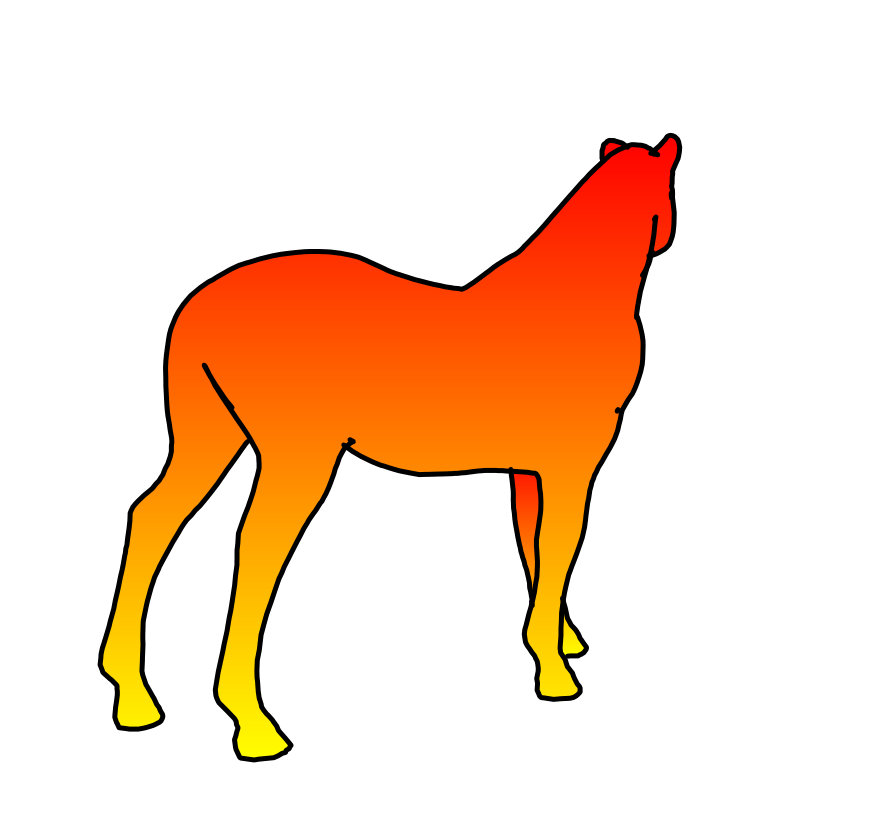 Figure 2
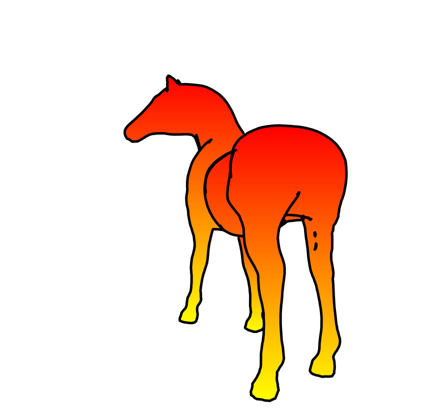 Figure 2
 Figure 2
 Figure 2
 Figure 2
 Figure 2
 Figure 2
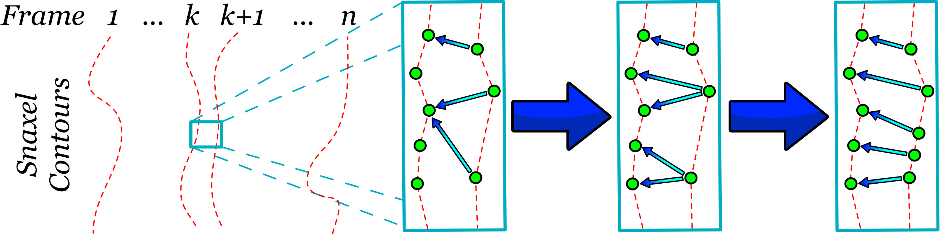 Figure 11
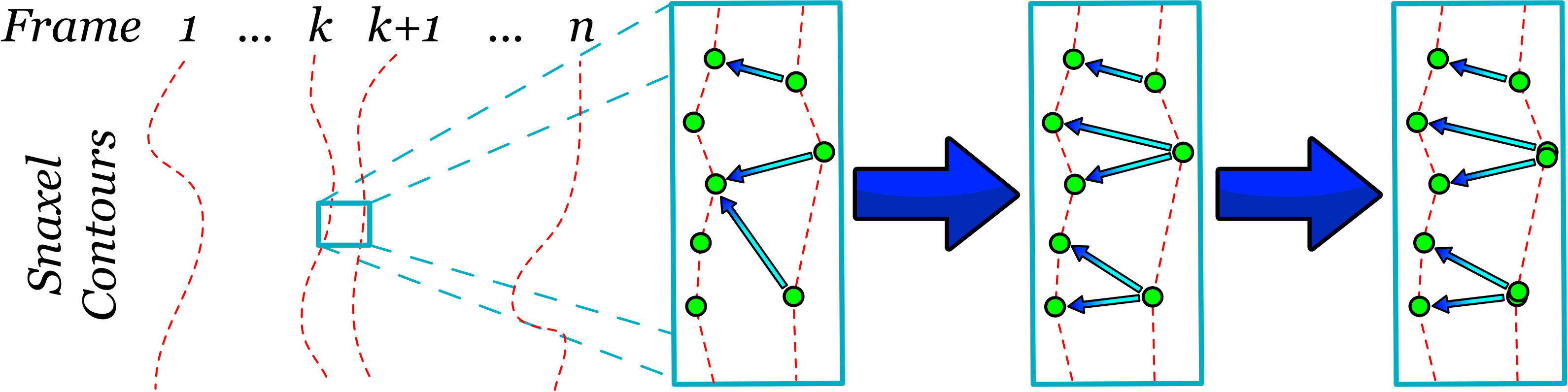 Figure 12
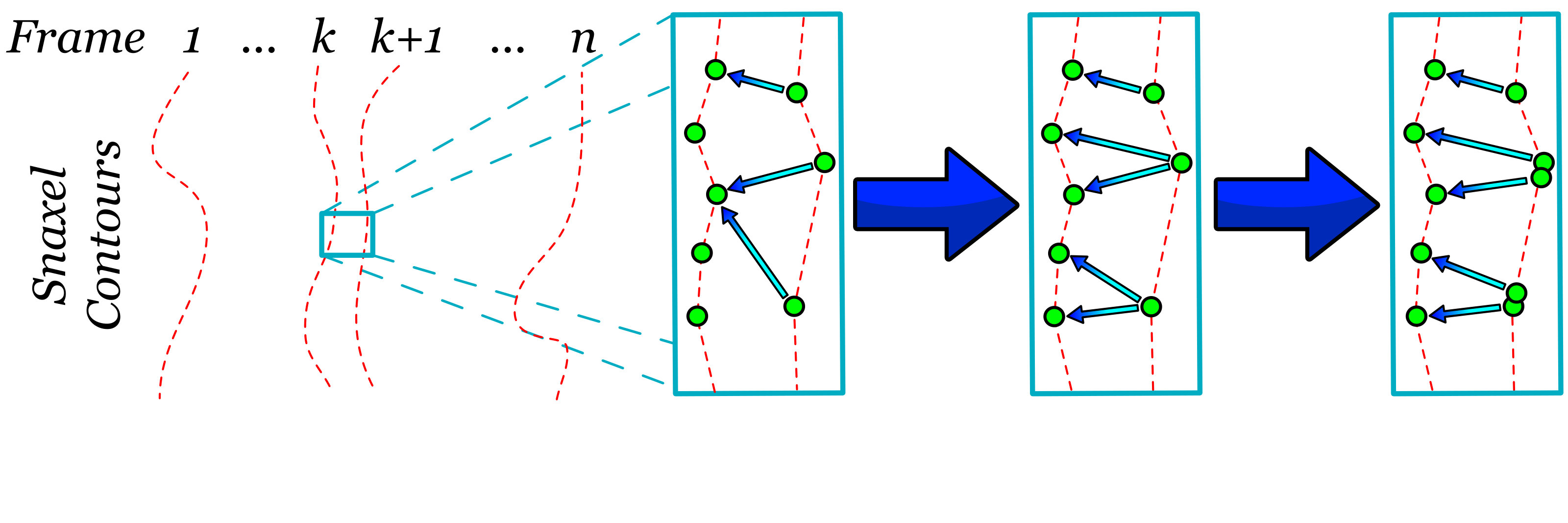 Figure 13
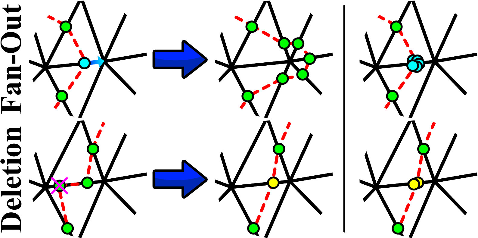 Figure 14
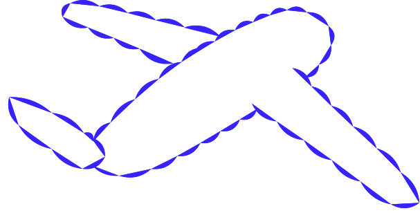 Figure 15
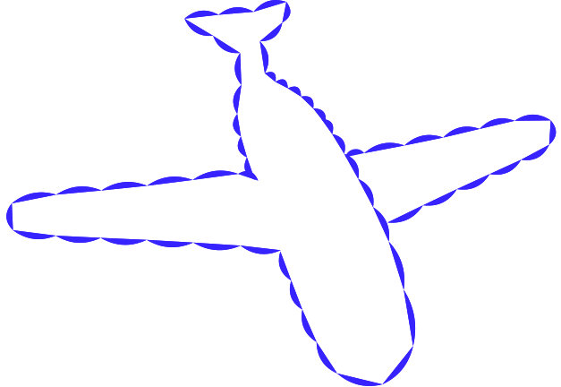 Figure 16
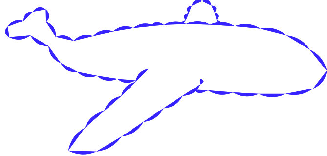 Figure 17
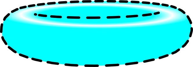 Figure 18
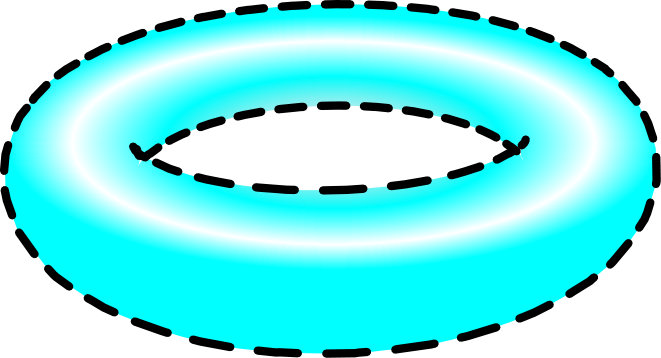 Figure 19
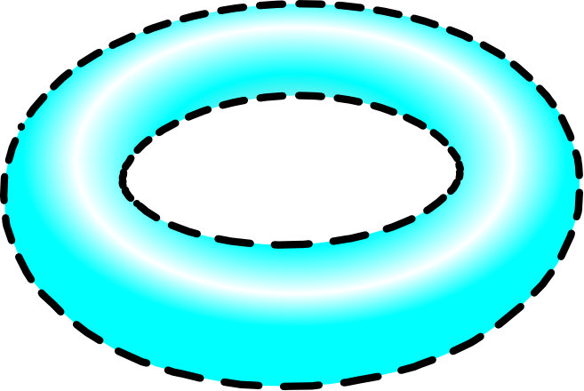 Figure 20
 Figure 21
 Figure 22
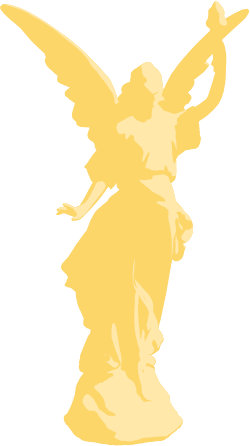 Figure 23
 Figure 24
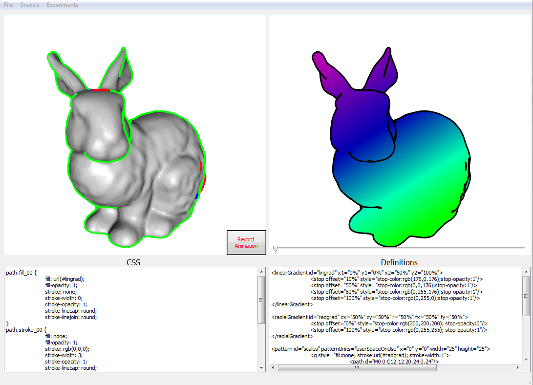 Figure 25
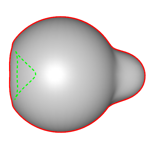 Figure 26
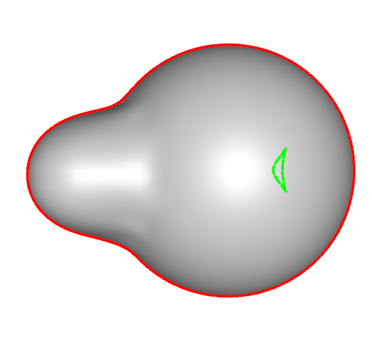 Figure 27
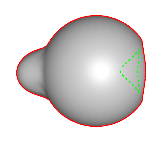 Figure 28
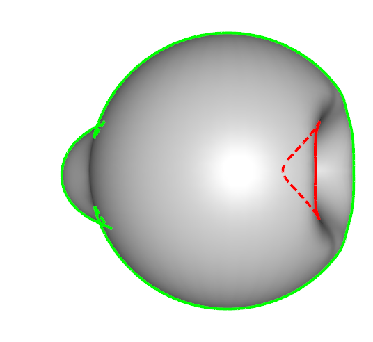 Figure 29
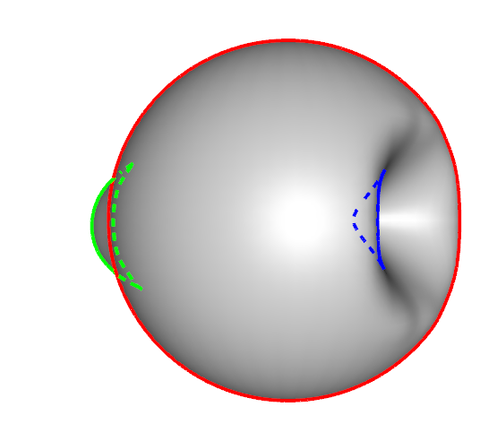 Figure 30
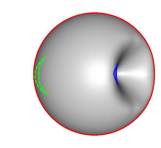 Figure 31
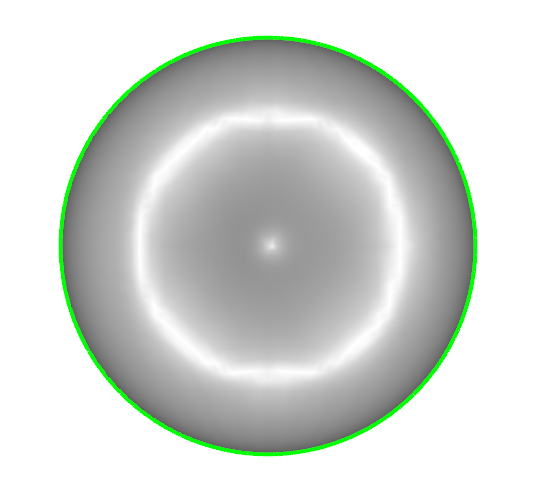 Figure 32
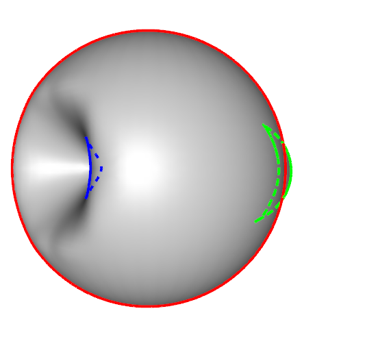 Figure 33
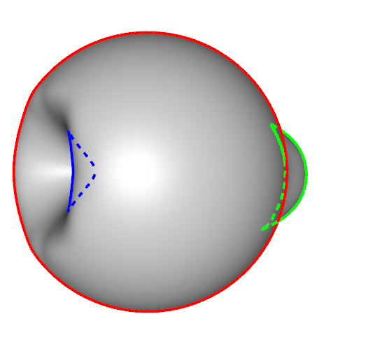 Figure 34
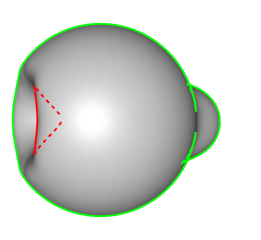 Figure 35
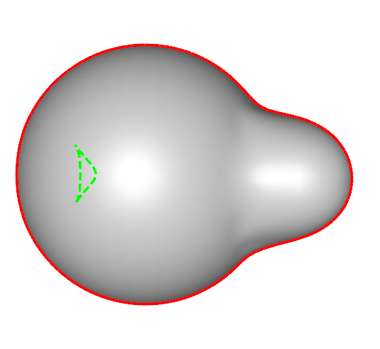 Figure 36
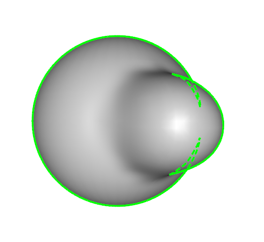 Figure 37
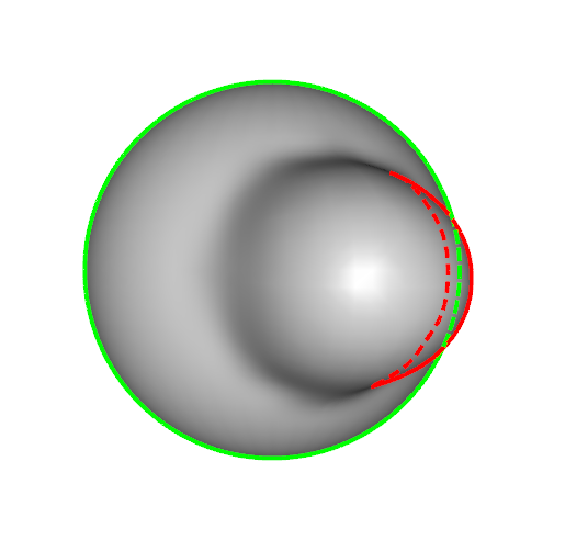 Figure 38
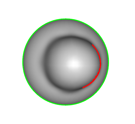 Figure 39
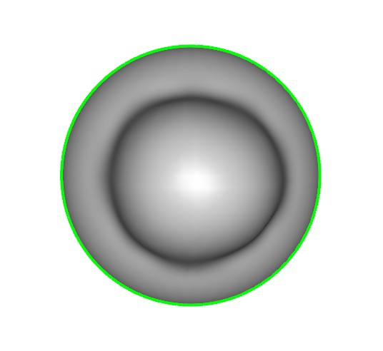 Figure 40
Peer Reviews
No public reviews on file for this paper yet. If you reviewed it on a platform where reviews are public (OpenReview, ICLR, NeurIPS, ICML), you can paste yours below so the community can read it here.
Videos
No videos yet. Explain this paper in a talk, walkthrough, or lecture? Add one.
\TOGvolume
0 \TOGnumber0 \TOGarticleDOI1111111.2222222 \TOGprojectURL \TOGvideoURL \TOGdataURL \TOGcodeURL
\pdfauthorKevin Karsch, John C. Hart
\teaser
This cartoon was generated by projecting snaxel fronts onto the view plane. The snaxel fronts find and track the visual, shadow and shading contours, and also form the planar map of the regions they bound, to simplify vector art construction, stylization and animation.
Snaxels on a Plane
Kevin Karsch John C. Hart
University of Illinois at Urbana-Champaign
{karsch1
jch}@illinois.edu
Abstract
While many algorithms exist for tracing various contours for illustrating a meshed object, few algorithms organize these contours into region-bounding closed loops. Tracing closed-loop boundaries on a mesh can be problematic due to switchbacks caused by subtle surface variation, and the organization of these regions into a planar map can lead to many small region components due to imprecision and noise. This paper adapts “snaxels,” an energy minimizing active contour method designed for robust mesh processing, and repurposes it to generate visual, shadow and shading contours, and a simplified visual-surface planar map, useful for stylized vector art illustration of the mesh. The snaxel active contours can also track contours as the mesh animates, and frame-to-frame correspondences between snaxels lead to a new method to convert the moving contours on a 3-D animated mesh into 2-D SVG curve animations for efficient embedding in Flash, PowerPoint and other dynamic vector art platforms.
keywords:
contour, line/vector art, planar map, SVG
\keywordlist
\TOGlinkslist
\copyrightspace
1 Introduction
The automatic conversion of meshed surfaces into stylized vector art has become a useful tool for generating illustrations, instructions and visual accompaniments. Early work focused on simulating a hand-drawn sketched appearance that could be generated from disjoint contour elements, e.g. [\citenameWinkenbach and Salesin 1994], whereas many more modern techniques rely on topologically correct closed-loop visual contours whose planar map bounds image regions, e.g. [\citenameEisemann et al. 2009]. Such contours are useful for stylization, e.g. [\citenameGrabli et al. 2004], and diffusion gradients, e.g. [\citenameOrzan et al. 2008].
While finding the elements of a visual contour from a meshed surface can be straightforward, continuing them into region-bounding closed loops and forming their planar map can require intricate geometric operations for correctness and robustness, c.f. [\citenameGangnet et al. 1989, \citenameAsente et al. 2007, \citenameStroila et al. 2008, \citenameEisemann et al. 2008, \citenameEisemann et al. 2009].
We propose a significantly simpler approach that efficiently and robustly (1) extracts closed-loop visual, shadow and shading contours and the regions they define, (2) forms a visible-surface planar map of simple, mesh resolution components and (3) provides correspondences between contours over time to convert 3-D contour motion into 2-D curve motion, to convert illustrations of dynamic 3-D objects into dynamic vector art.
This simpler approach is built on snaxels, a surface contour formulation previously designed to support active contour propagation over a meshed surface [\citenameJung and Kim 2004] instead of their original domain of the regular grid structure of an image [\citenameKass et al. 1988]. The original snaxel active contours are formulated as an energy minimization over an irregular meshed domain embedded in 3-D. Section 3 focuses this formulation on the specific problem of extracting illustration contours, which simplifies its construction and implementation. For example, we replace the energy functional with an implicit contour function and revise the integration appropriately. By definition, these active contours are level sets (of regular values) and hence form and maintain closed loops. The snaxel approach robustly tracks these closed loop contours, subdividing and merging as necessary as the system tracks their shape through changes in the surface, view and lighting.
Section 4 defines implicit contour functions for the visual contour generator as well as shadow and shading contours. It also shows how to initialize the snaxels to capture these contours and the regions they define. It further describes how to track these contours on a moving surface. The snaxels detect and adapt visual contour topology across visual events, and these events can be used to detect the presence of parabolic points on a meshed surface.
Section 5 shows how the snaxel evolution rules can be modified to generate a visible-surface planar map. While such a planar map can be generated through computational geometry techniques, the snaxel implementation is far simpler, and the mesh-constrained resolution of the snaxel formulation naturally filters out the geometric noise of small components that sometimes accompany precise arithmetic approaches.
Once the visual and other contours are defined, Section 6 shows how the snaxel formulation can be used to convert the 3-D motion of surface contours into the 2-D motion of image curves. The evolution of the snaxel front provides the correspondences between the contours of each frame, providing a natural framework for animating the contours and their stylization into, e.g. animated SVG, in a form that can be compactly and conveniently inserted into Flash, PowerPoint or other dynamic vector art platforms.
Section 7 concludes with a summary, demonstration of our interactive system for extracting and stylizing contours on animated meshes, and a discussion of the directions of further research inspired by this novel approach to contouring for illustrating meshed objects.
2 Previous Work
For a general view, the visual contours of a shape form closed loops. Numerous techniques exist for extracting silhouettes and other contours from a meshed object [\citenameMarkosian et al. 1997, \citenameElber 1998, \citenameKalnins et al. 2003, \citenameDeCarlo et al. 2003, \citenameSu and Hart 2005, \citenameBurns et al. 2005, \citenameOlson and Zhang 2006, \citenameJudd and Durand 2007]. Many fewer methods exist that connect them into region-bounding closed loops, which supports planar map construction and various region stylization methods, ranging from hatching [\citenameWinkenbach and Salesin 1994] to diffusion gradients [\citenameOrzan et al. 2008]. A popular survey of silhouette algorithms for polygonal models [\citenameIsenberg et al. 2003] focuses on other issues than forming closed loops and bounding regions.
The visual contour and other contours that follow edges of a mesh suffer from well-known problems with switchbacks [\citenameRusinkiewicz 2008], indicated by extraneous triangles along the contour path. Past work has confronted this problem by subdividing the mesh near the visual contour [\citenameWinkenbach and Salesin 1996], interpolating surface normals across edges [\citenameHertzmann and Zorin 2000] or extending a jagged shadow contour outward into a smooth contour. As shown previously [\citenameEisemann et al. 2008], care must be taken when tracing and integrating regions and contours extracted from interpolated vectors, as the visual contour may not precisely surround the projection of the surface mesh, leading to downstream region classification problems.
The proposed snaxel method for contour tracking likewise interpolates surface normals across the edges, but could further smooth the contour by adding a smoothness term to the snaxel energy functional. We extract a planar map through modified snaxel rules that avoid the classification problems that could arise when post-processing a planar map from the contours based on interpolated vertex normals.
Extraction of region-bounding contour loops and their planar map is complex and has been fraught with robustness issues [\citenameGangnet et al. 1989, \citenameAsente et al. 2007]. The region-robust contour loop and planar map extraction of Eisemann et al. [\citenameEisemann et al. 2008] relied on CGAL’s Arrangement package. The “view-map” layered planar map structure of Eisemann et al. [\citenameEisemann et al. 2009] is also numerically robust but only through special tolerancing described by a separate appendix. The snaxel approach simplifies these robustness issues by maintaining a planar map during active contour evolution.
The snaxel visual contour approach builds on the idea of propagating contour samples of Coherent Stylized Silhouettes [\citenameKalnins et al. 2003] and earlier work [\citenameBourdev 1998]. That work used chains of contour samples that adhered to the visual contour as it moved but focused on maintaining consistent contour decoration throughout an animated sequence. In particular it did not confront the changes in contour topology caused by visual events, which the snaxel approach handles robustly and simply. Because of their similarity, the methods used for coherent stylized silhouettes apply directly to the evolving contours produced by snaxels.
3 Snaxels Redux
Snaxels are active contours (a.k.a. “snakes” [\citenameKass et al. 1988]) lifted from the regular grids of a planar image to work on the irregular grid of a meshed surfaces embedded in 3-D. In this form, snaxels have been useful for segmenting mesh features [\citenameJung and Kim 2004], detecting relief on meshes [\citenameLiu et al. 2006] and a variety of other applications. Snakes are an attractive approach for many applications because of their robustness and their behavior is controlled primarily by the choice of which “energy” they should seek to minimize. Here we review the relevant snaxel details and show how to adapt the framework to find and track the contours commonly used for illustration.
Summarizing Bischoff et al. \shortciteBischoff:2005va, we represent an active contour on a surface mesh as a collection of “snaxels,” points traveling along the edges of the mesh, and each snaxel is connected to each of its two neighboring snaxels by a segment lying on the face of the mesh.
Representation: Each snaxel lies on a mesh edge
[TABLE]
an edge-normalized distance from start vertex to end vertex and is connected to neighboring snaxels referenced as and by line segments across edge-neighboring faces. 2. 2.
Update: The snaxels evolve the active contour as
[TABLE]
where is a time step (we use 0.1), and is an implicit contour function, evaluated at snaxel position designed to lead the snaxels over the meshed surface to the contour. Active contours are often designed using an energy functional in which case 3. 3.
Fan-Out: If then create a new snaxel on every edge adjacent to with parameter else if then do the same about with parameter 4. 4.
Topology: Delete any two snaxels sharing an edge and connect the pair of dangling snaxels on the left face and again on the right face.
Figure 1 illustrates these rules.
We implement each active contour as a doubly-linked circular list to efficiently support the many insertions and deletions of snaxels as the contours evolve over the meshed surface. The topological operations can sometimes yield small contours consisting of only one or two snaxels, which can be tested and deleted during a cleanup sweep through the snaxels.
4 NPR Contouring
The snaxel framework described in the previous section is used to track active contours that seek to minimize an energy functional. If we define the energy functional appropriately, these active contours can track the contours used for illustrative and expressive rendering algorithms.
Most importantly, snaxels can be used to extract the visual contour generator. The visual contour generator forms the visible and hidden outlines of an object embedded in the object surface in 3-D, defined on a smooth surface by the points where the view vector is tangent to the surface. Hence we define the implicit contour function for the visual contour generator as
[TABLE]
where is the surface normal at and is a direction vector at pointing toward the viewer.
For a meshed surface, we define the normal vector at snaxel along edge as the spherical linear interpolation of the normals defined at the vertices
[TABLE]
where is the angle between the normals, and assume the limit as Figure 2 demonstrates a snaxel front propagating across a torus while adhering to the implicit contour function as in Eq. 3.
As shown previously [\citenameEisemann et al. 2008], using normals interpolated from vertex normals to extract a smooth visual contour generator over mesh faces instead of edges [\citenameHertzmann and Zorin 2000], can lead to a silhouette that might not strictly contain the projection of the mesh. When a smoothed silhouette curve segment traverses a face, the entire face is either visible or occluded and when visible includes the portion outside the silhouette curve. This can be problematic when classifying regions on the projection or intersecting multiple contours (e.g. visual contour with shadow contour to segment visible illuminated portions from visible shadowed portions). As shown in the next section, the planar map produced by revised snaxel rules avoids such misclassifications.
We can likewise generate a shadow contour and isophotes of diffuse illumination by setting the implicit contour function to
[TABLE]
where is a direction vector from vertex toward a light source, and is the isovalue of the isophote. For example, if then Eq. 5 generates a shadow contour whereas setting generates a contour of constant diffuse reflection. The minimum between the two terms is taken so that snaxels on isophote contours do not lie on backfacing polygons, which allows for stylization as illustrated in Fig. 3.
The interaction between snaxels of different types (e.g. visual contour v. shadow contour) depends on the form of planar map used, as described in the next section. For example, if a planar map is post-processed, then visual contour snaxels would not interact with shadow contour snaxels. But if the snaxel method for planar map generation is used, then the two kinds of snaxels would indeed interact with each other.
4.1 Initialization
Snaxels must be created properly to ensure that every contour-bounded region is tracked and generated. Since we seek contours where we initialize contours at the (local) extremes of as shown in Figure 4. As this figure shows, smooth surfaces benefit from fewer initialization points and need less merging, whereas noisier meshes, such as those reconstructed from scanned points, generate many initial contours that require significant merging into the visual contour generator. We have found the snaxel framework is robust enough to nevertheless handle such cases.
Since the snaxel front expands through all vertices as it descends (splitting and merging as necessary) from local maxima to a zeroset contour, it can label vertices as its sweep defines the region bounded by the active contour. Hence the snaxel approach not only generates region bounding contours but also labels all vertices (and edges and faces if needed) within the region. These region delineations can be convenient for various region-based stylization methods.
Some contours could be more problematic, such as small specular highlights. Phong reflectance can be used as an implicit contour function
[TABLE]
which generates contours surrounding specular gleams. However, as Phong showed, these contoured gleam regions can occur between vertices, and so contain no vertex, and these specular regions might be missed by a per-vertex snaxel initialization.
4.2 Animation
In addition to growing visual and other contours on meshed surfaces, the snaxel approach is particularly good at tracking existing contours as the surface changes. These contours change as the view changes, the light position moves or the surface rotates, and also as a dynamic mesh changes shape. In these cases, the snaxels need not be reinitialized from scratch but can simply evolve to correct the contour to the new situation; figure 6 shows an example of this.
As the contours move to accommodate changing views, lighting and shape, we maintain the contour region labeling. Each vertex keeps track of whether or not a front has visited it, and such visits only occur during the “fan-out” stage of snaxel propagation. Since merging and splitting events happen only on mesh edges, this visited flag is unaffected by topology changes.
When the view of a surface changes, the visual contour generator can undergo topological changes, which are denoted as visual events. These visual events can cause contours to divide or merge, or to be created or destroyed. The flexible topology of snaxel evolution handles the divide and merge cases, and the snaxel cleaning phase manages the annihilation of entire contour loops. The remaining case is the creation of a contour loop, which is difficult because there may not be any snaxels near the point where a new contour appears.
At each frame in the animation, snaxels are initialized at extrema of ; however, we ensure that snaxel fronts are not created around any vertex that has already been visited by a snaxel front. Since we search for all extrema of (rather than only minima or maxima), we detect backfacing and occluded visual contours as well as frontfacing visual contours. Several such contours are properly detected and shown in three frames of the rotating “nose” example shown in Fig. 6.
4.3 Mesh Parabolic Points
On smooth surfaces, the location where a visual event causes a change in the topology of the visual contour generator occurs at a parabolic point. These are points where the Gaussian curvature vanishes because one of the principle curvatures is flat. Such positions have been difficult to precisely locate on meshed surfaces. Curvature measures on meshed surfaces are notoriously susceptible to noise and other problems, yielding some to resort to a full global fitting of an implicit surface to a mesh just to evaluate curvature over the mesh [\citenameOhtake et al. 2004]. The Gaussian curvature of a mesh is zero everywhere except its vertices, but typically all curvatures on a mesh are evaluated with respect to its vertices, which further confounds the detection of parabolic points.
We can use the snaxel framework to detect parabolic points on a mesh. By sampling the sphere of (orthographic) view directions, we can evolve the visual contour generator over the mesh. When the snaxels defining this contour alter topology, we can mark that location as a parabolic point. Figure 7 demonstrates some examples of these markings.
5 Planar Map Generation
Given several sets of overlapping contours (e.g. the visible and occluded visual contour generator, shadow contour and other shading contours) and the regions they delineate, the planar map decomposes them into a planar graph of homogeneous regions. The planar map can be constructed of just visible portions of a surface, or can consist of all surfaces, visible and occluded, in which case regions in the planar map share depth complexity in addition to other region attributes.
Given the overlapping visual, shadow and shading contours generated from the previous section, a planar map can be generated as a post-process, e.g. by the CGAL Arrangement package [\citenameFlato et al. 2000, \citenameWein et al. 2005] or the General Polygon Clipper library [\citenameMurta 1999] (based on [\citenameVatti 1992]), as shown in the center row of Figure 8. Such processing requires integration of a rather heavyweight library, and can yield numerous small regions (see e.g. [\citenameBiermann et al. 2001]) that can hinder stylization.
A specific problem that can occur when post-processing a planar map from extracted contours is that the contours may not precisely bound the projections of the regions they represent [\citenameEisemann et al. 2008]. The silhouette formed by the visual contour extracted from interpolated vertex normals does not strictly contain the projection of the mesh, and other contours on the mesh may escape its bounds. A post-processed planar map in these cases would yield small regions near these imprecise locations caused by the approximation of normal interpolation.
The snaxel formulation can be modified to generate a planar map that fixes these problems, providing further control over precision and stylization as well as simplifying implementation. To generate a planar map, we amend the snaxel topology rules as follows:
We detect collisions between snaxels of any type (visual, shadow, shading). 2. 2.
We detect snaxel collisions in the image plane as well as on mesh edges. We hence maintain the projection of each snaxel on the image plane in addition to its position on the mesh edge. 3. 3.
Snaxel fronts of the same type that collide on the 3-D surface are allowed to merge and split, but snaxel fronts of different types whose image projections collide are not allowed to merge, and instead push against each other. 4. 4.
Occluded fronts must yield to visible fronts when their projections collide. Similarly, “darker” isophote contours must yield to “brighter” isophote contours (e.g. a contour with will have precedence over another contour with ).
These rules generate a visible-surface planar map consisting of regions of different combinations of shading (e.g. illuminated v. shadow). These rules are easily expressed in terms of a new energy functional
[TABLE]
where is the chosen energy function (e.g. Eq 3, 5, or 6). The statement “ is within a closer front” means that the snaxel is inside of the 2D polygon defined by another front’s image-space projection, and that the given front is closer to the camera than . Figure 9 demonstrates snaxels propagating over a mesh while adhering to these rules; equivalently, deforming based on Eq. 7.
We keep track of snaxel position on the mesh edges as well as their projected positions in the image plane. To detect when snaxel fronts overlap in image-space, we use the even-odd-rule algorithm, which also ensures that no contours are self-intersecting. Such tests can be expensive for large meshes, and collisions may also be detected at raster resolution using other, less expensive techniques (e.g. occlusion queries).
Initialization can be tricky for planar map evolution. Ideally one would want a snaxel front initialized for every planar map region, but these regions are not known a priori. Hence we test the mesh vertices after a planar map has been generated to ensure the snaxel-defined regions match their actual classification (e.g. a vertex in the shadowed region is actually shadowed). Any mis-classified vertices are reinitialized with corrected fronts and the planar map is refined.
Snaxels define an active contour front based on snaxel positions along edges, and when they form a visible-surface planar map they overcome the problems caused by an approximate silhouette generated by interpolated vertex normals. The snaxels live on mesh edges, and by definition form loops that enclose regions, to a resolution defined by the surface mesh tessellation. Hence small mesh corners exposed beyond an imperfect interpolated-normal smoothed silhouette are not tessellated enough to support an isolated snaxel front (including any discovered by the aforementioned re-initialization pass) and so are conveniently filtered away by the snaxel visible-surface planar map.
6 3-D SVG Animation
Our snaxel framework allows us to convert frame-based NPR animations into 2-D, keyframed animations of projected outline curves and regions. In other words, we can represent animated vector art not as a sequence of individual vector art frames, but as a smaller subset of keyframes, interpolating the outline curves between them by moving their vertices. The advantage of such a representation for animated vector art are its compactness and intuitive representation, as well as its support for temporally coherent stylization [\citenameKalnins et al. 2003].
The main challenge of converting the motion of a 3-D surface contour into the motion of its 2-D projection is the correspondence of the curve representation across frames of the animation. Given an animation sequence, such as rotating or deforming a meshed object, the snaxel fronts will evolve to produce contours for each frame of the sequence. The snaxels defining these contours provide the necessary support to generate correspondences from frame to frame.
SVG polyline animation does not support changes in topology, so we insert keyframes at every contour topology change event, breaking the spacetime contour into contour sequences that do not change topology, and process the snaxels of each contour sequence into the vertex motion of an animated polyline. Such animation also requires each contour within a given sequence to have the same number of vertices, which we achieve by detecting temporal correspondences between vertices, and then appropriately adding colocated vertices based on these correspondences (see Fig 10).
If a snaxel simply moves along its mesh edge, then a correspondence can be easily drawn between its start position and end position. When a snaxel is deleted, we do not actually delete it but instead colocate it with the closer of its two neighbors in the contour. When a snaxel undergoes a fan-out operation, we replace the snaxel with multiple colocated copies of the snaxel, each copy corresponding to one of the snaxels generated by the fan-out (as in Fig 10). Often a fan-out generates several subsequent deletion events. We detect this case to avoid excessive duplication and colocation of snaxels. These snaxels, along with their colocated copies, become the vertices of animated polylines representing the 2-D curve motion of the 3-D contour on the animated mesh surface. Figure 11 shows two animation sequences converted into 2-D keyframed animation using our technique.
With the tracking method presented here, we can use snaxels to reproduce the coherent stylized silhouettes of Kalnins et al. \shortcitekalnins03, as demonstrated in Figure 12. Because we know the correspondences and the snaxels’ 3-D position as well as their 2-D positions in the image space, we can sample the polylines defined by the snaxels (in 2D, 3D, or a mixture of both) to achieve temporally coherent silhouettes. Furthermore, when snaxel contours change topology, the snaxel positions provide a basis for reparameterizing the contours with a reasonable level of coherence across a topology change or visual event, avoiding the “pop” discussed by Kalnins et al. \shortcitekalnins03.
7 Conclusion
We have shown that snaxels, a formulation for active contours on unstructured meshes, supports a variety of useful operations for constructing stylized vector art illustrations of meshed surfaces. The flexible topology of snaxel fronts allows them to evolve into visual and other contours, and to track these contours across various changes in shape, view and lighting. Adjusting the snaxel rules allows them to produce a useful visible surface planar map, and by tracking the snaxel positions themselves as a shape is animated, the 3-D motion of the surface contours can be converted into 2-D motion of animated SVG curves and polylines.
Snaxels also provide a simple and quick mechanism for achieving other state-of-the-art results, such as coherent stylized silhouettes [\citenameKalnins et al. 2003] (Fig. 12) and the mesh-based stylized vector art of Eisemann et al. \shortciteEisemann_cgf08 (Fig. 14).
Perhaps the most compelling aspect of the snaxel formulation is that it can be expressed with a few simple rules, and is easy to implement on an edge-based mesh representation. Our CPU implementation achieves interactive speeds for meshes with up to 100K faces, which sufficed for all results in this paper. Larger meshes could be supported by a parallel snaxel implementation, e.g. on the GPU. The snaxel update process can be directly parallelized, though fan-out, deletion and topology changes pose challenges for efficient streaming parallelization due to their irregular control flow.
We developed an intuitive interface to capture mesh-based animations as vector art, demonstrated in Figure 13. The interface displays both the 3-D snaxel contours on the surface and their projections (and regions) on the view plane. The image rendering is SVG based, implemented with the Qt framework, and includes text windows for editing and applying various stylizations. Some examples of our resulting stylizations are demonstrated in Figure 14.
This investigation of snaxels for NPR contouring has resulted in numerous ideas for future research. The snaxel rules themselves could be stylized, to enforce e.g. smoothness or shape constraints. A maximum area constraint on snaxel regions might yield a cellular/scaled/bubble region stylization.
The conversion of 3-D surface contour motion into 2-D curve motion should be explored further. Projected contours can be simplified from detailed polylines to simpler, smoother piecewise cubic curves, and the motions of the polyline vertices can be compiled, reduced and simplified into general control point motions.
Acknowledgements
We thank Mahsa Kamali and Victor Lu for their advice and discussions, as well as the reviewers for their helpful comments. This research was supported by the NDSEG Fellowship and the NSF Graduate Research Fellowship.
The reference list from the paper itself. Each links out to its DOI / PubMed record.
- 1[ \citename Asente et al . 2007] Asente, P., Schuster, M., and Pettit, T. 2007. Dynamic planar map illustration. (Proc. SIGGRAPH) ACM Trans. Graph. .
- 2[ \citename Biermann et al . 2001] Biermann, H., Kristjansson, D., and Zorin, D. 2001. Approximate boolean operations on free-form solids. In Proc. SIGGRAPH , 185–194.
- 3[ \citename Bischoff et al . 2005] Bischoff, S., Weyand, T., and Kobbelt, L. 2005. Snakes on triangle meshes. Bildverarbeitung für die Medizin , 208–212.
- 4[ \citename Bourdev 1998] Bourdev, L. 1998. Rendering nonphotorealistic strokes with temporal and arc-length coherence. Master’s thesis, Brown University .
- 5[ \citename Burns et al . 2005] Burns, M., Klawe, J., Rusinkiewicz, S., Finkelstein, A., and De Carlo, D. 2005. Line drawings from volume data. In Proc. SIGGRAPH, ACM TOG , 512–518.
- 6[ \citename De Carlo et al . 2003] De Carlo, D., Finkelstein, A., Rusinkiewicz, S., and Santella, A. 2003. Suggestive contours for conveying shape. Proc. SIGGRAPH, ACM TOG 22 , 3, 848–855.
- 7[ \citename Eisemann et al . 2008] Eisemann, E., Winnemöller, H., Hart, J. C., and Salesin, D. 2008. Stylized Vector Art from 3D Models with Region Support. Computer Graphics Forum 27 , 4 (jun).
- 8[ \citename Eisemann et al . 2009] Eisemann, E., Paris, S., and Durand, F. 2009. A visibility algorithm for converting 3d meshes into editable 2d vector graphics. (Proc. SIGGRAPH) ACM Trans. Graph. 28 , 83:1–83:8.