Level-set based design of Wang tiles for modelling complex microstructures
Martin Do\v{s}k\'a\v{r} (1), Jan Zeman (1, 2), Daniel Rypl (1), Jan, Nov\'ak (1) ((1) Faculty of Civil Engineering, Czech Technical University in, Prague, (2) Institute of Information Theory, Automation)
TL;DR
This paper extends a microstructural generation framework to non-periodic Wang tiles, enabling the creation of complex, large, stochastic 3D microstructures with improved compatibility and reduced artificial periodicity.
Contribution
It introduces a robust procedure for designing complex 3D Wang tile morphologies and broadens the tiling concept's applicability for microstructure modeling.
Findings
Vertex-defined tile sets outperform in 2D microstructure generation.
The method effectively reduces artificial periodicity in reconstructed samples.
Demonstrated capabilities in 2D and 3D microstructure synthesis.
Abstract
Microstructural geometry plays a critical role in the response of heterogeneous materials. Consequently, methods for generating microstructural samples are increasingly crucial to advanced numerical analyses. We extend Sonon et al.'s unified framework, developed originally for generating particulate and foam-like microstructural geometries of Periodic Unit Cells, to non-periodic microstructural representations based on the formalism of Wang tiles. This formalism has been recently proposed in order to generalize the Periodic Unit Cell approach, enabling a fast synthesis of arbitrarily large, stochastic microstructural samples from a handful of domains with predefined compatibility constraints. However, a robust procedure capable of designing complex, three-dimensional, foam-like and cellular morphologies of Wang tiles has not yet been proposed. This contribution fills the gap by…
Peer Reviews
No public reviews on file for this paper yet. If you reviewed it on a platform where reviews are public (OpenReview, ICLR, NeurIPS, ICML), you can paste yours below so the community can read it here.
Videos
No videos yet. Explain this paper in a talk, walkthrough, or lecture? Add one.
Level-set based design of Wang tiles for modelling complex microstructures111Author’s post-print version of the article manuscript published in Computer-Aided Design
DOI: 10.1016/j.cad.2020.102827.
Martin Doškář
Jan Zeman
Daniel Rypl
Jan Novák
Department of Mechanics, Faculty of Civil Engineering, Czech Technical University in Prague, Thákurova 7, 166 29 Prague 6, Czech Republic
The Institute of Information Theory and Automation, Academy of Sciences of the Czech Republic, Pod Vodárenskou věží 4, 182 08 Prague 8, Czech Republic
Experimental centre, Faculty of Civil Engineering, Czech Technical University in Prague, Thákurova 7, 166 29 Prague 6, Czech Republic
Abstract
Microstructural geometry plays a critical role in the response of heterogeneous materials. Consequently, methods for generating microstructural samples are increasingly crucial to advanced numerical analyses. We extend Sonon et al.’s unified framework, developed originally for generating particulate and foam-like microstructural geometries of Periodic Unit Cells, to non-periodic microstructural representations based on the formalism of Wang tiles. This formalism has been recently proposed in order to generalize the Periodic Unit Cell approach, enabling a fast synthesis of arbitrarily large, stochastic microstructural samples from a handful of domains with predefined microstructural compatibility constraints. However, a robust procedure capable of designing complex, three-dimensional, foam-like and cellular morphologies of Wang tiles has not yet been proposed. This contribution fills the gap by significantly broadening the applicability of the tiling concept.
Since the original Sonon et al.’s framework builds on a random sequential addition of particles enhanced with an implicit representation of particle boundaries by the level-set field, we first devise an analysis based on a connectivity graph of a tile set, resolving the question where a particle should be copied when it intersects a tile boundary. Next, we introduce several modifications to the original algorithm that are necessary to ensure microstructural compatibility in the generalized periodicity setting of Wang tiles. Having established a universal procedure for generating tile morphologies, we compare strictly aperiodic and stochastic sets with the same cardinality in terms of reducing the artificial periodicity in reconstructed microstructural samples. We demonstrate the superiority of the vertex-defined tile sets for two-dimensional problems and illustrate the capabilities of the algorithm with two- and three-dimensional examples.
keywords:
Microstructure generation, Random heterogeneous materials, Wang tiling, Level sets, Foam microstructures, Cellular microstructures
††journal: arXiv.org
1 Introduction
The geometrical details of a material composition drive many macroscopic phenomena such as crack initiation and propagation [1] or meta-behaviour [2]. Advanced computational strategies thus tend to incorporate knowledge of material microstructures222We use the term “microstructure” in a broader sense, without referring to a specific scale length. in order to enhance their predictive power. [3]
When micro and macro scales are well separated, a microstructural response is typically up-scaled through homogenization methods. Albeit computationally intensive, numerical homogenization methods [3] now supersede analytical methods [4] because of their ability to handle complex microstructural geometries and non-linear problems. With increasing computational power, numerical models that fully resolve the microstructural geometry in the whole macroscopic domain, e.g. [5, 6], or in regions of interest [7, 8], have emerged, addressing problems without clear scale separation.
For both strategies, however, accuracy critically depends on the representativeness of the provided microstructural geometry, accenting the crucial role of microstructure modelling in multi-scale approaches.
Compared to materials with regular microstructures, characterized entirely by Periodic Unit Cells (PUCs), modelling random heterogeneous materials is more intricate; any finite-size representation automatically implies information loss. The optimal microstructure representation should capture intrinsic randomness and fluctuations in a microstructure while remaining computationally tractable (for numerical homogenization) or inexpensive to construct (for fully resolved simulations).
1.1 State-of-the-art in modelling random microstructures
One of the widely adopted approaches for modelling heterogeneous materials rests on an extension of PUC generated such that its spatial statistics match that of a reference microstructure. This procedure appears in the literature under various names such as Statistically Optimal Representative Unit Cell [9], Repeating Unit Cell [10], Statistically Similar Representative Volume Element [11], or Statistically Equivalent Periodic Unit Cell (SEPUC) [12], among others. The spatial statistics involved range from Minkowski functionals [13] to multi-point probability functions [4], out of which the two-point probability [14, 15, 16], two-point cluster [17], and lineal path [18, 19, 12, 20] functions are the most frequently used.
Following Povirk’s seminal work [21], the majority of cell representations are generated using optimization procedures, minimizing the discrepancy between the statistical characterization of the reference microstructure and its compressed, PUC-like representation. The particular choice of optimization algorithm currently varies with several options including simulated annealing [22, 19, 12], genetic [23, 24, 9, 10] and gradient [21, 25], or phase-recovery [26] algorithms.
The second approach to microstructure generation utilizes reference samples of the microstructure. New realizations are then obtained with a Markovian process, taking individual voxels [27] or a patch of voxels [28] from the provided reference samples according to the proximity of the spatial statistics computed for their surroundings. Alternatively, searching for statistics proximity can be replaced with a classification tree-based supervised learning model [29].
The previous two approaches suffer from high computational costs related either to optimization or to training the learning models. The applicability of their outputs is also sensitive to the spatial statistics considered, attesting to the ill-conditioning of the microstructure reconstruction problem itself. Achieving a good match in selected statistics does not automatically guarantee similar overall behaviour; for instance, Biswal et al. [30] demonstrated that realizations with similar two-point probability functions could have significantly different percolation characteristics that govern overall transport properties.
Complementary to the statistics-informed methods, a third approach to generating microstructural realizations relies on meta-modelling the genesis of a microstructure. These methods range in complexity and include the Monte-Carlo Potts [31] and phase field models [32] of grain growth; sedimentation-and-compaction models [30]; and various particle packing algorithms, e.g. [33, 34, and references therein], based on either Random Sequential Adsorption (RSA)333In its simplest setting of packing circular or spherical particles, RSA corresponds to the Dart Throwing Algorithm [35]. [36, 37] or molecular dynamics [38, 39, 40].
The relevance of packing algorithms extends beyond simple particle-matrix microstructures because the resulting packings often serve as initial seeds for tessellation-based models applicable to polycrystals [41, 42], foams [34], and cell tissues [43, 44]. Due to its straightforward implementation, Voronoï tessellation is the most common choice; however, the resulting geometry is oversimplified for many materials. For instance, Voronoï-based models overestimate overall stiffness for high porosity foams [45]. The curvature of the cell walls [41, 46] and heterogeneity in cell size [34, 42] and wall thickness [42] must be additionally introduced to obtain realistic geometries. Similar effects can be achieved by modifying the distance measure used during tessellation, e.g. models based on the Laguerre variant generate microstructures with multi-mode cell size distribution [47, 42, 34, 33]. Inspired by Laguerre tessellation, Chakraborty et al. [44] proposed Adaptive Quadratic Voronoï Tessellation, attributing a distinct anisotropic metric to each seed and thus allowing for additional control over the resulting geometry.
The original RSA method [35] suffers from complexity for particles due to overlap checks and is impractical for generating large, densely packed systems. Consequently, several accelerations have been proposed. For Dart Throwing Algorithm [35], which is a simplified case of RSA with equisized circular/spherical particles, Dunbar and Humphreys [48] introduced a scalloped sector representation of non-overlap guaranteed regions. In the same year, Jones [49] proposed an alternative bookkeeping of the regions based on an adaptively updated Voronoï tessellation. Moreover, both approaches utilize a tree data structure and improve the algorithm complexity to . For general RSA, Yang et al. [10] proposed an acceleration based on a combination of a spline description of particle shapes and hierarchically refined bounding boxes of each particle. Recently, Sonon et al. [50] introduced a method building on an implicit, level-set based description of particle shapes, achieving complexity (see Section 3.3 in [50]). Moreover, Sonon et al.’s method readily facilitates generating complex microstructures using linear combinations of the nearest neighbour distance functions and dedicated morphing operations [50, 51, 52, 53]. In a sense, this approach introduces the anisotropic pseudo-metrics444Level-set description based on the signed distance to the th nearest particle boundary does not fulfil all metric criteria. of [44] in a geometrically-motivated way by considering arbitrarily-shaped particles. As a result, Sonon et al.’s method enables refined control over generated microstructure unattainable with standard Voronoï or Laguerre tessellations; see Section 3.2.
Albeit significantly faster than RSA or optimization-based approaches, the latter method still starts anew every time an additional realization is required, imposing overhead on, e.g., investigations of the Representative Volume Element (RVE) size that require multiple microstructural samples to be generated, see [54, 55, 56]. Alternatively, larger microstructural realizations can be assembled from (SE)PUC; however, such construction introduces non-physical, long-range, periodic artefacts in a microstructural geometry and its local response.
1.2 Wang tiling in microstructure modelling
Inspired by applications in computer graphics [58], we have introduced the formalism of Wang tiles as a suitable generalization of SEPUC representation of heterogeneous materials [59]. The formalism provides a compromise between the SEPUC approach and the use of a microstructure generator for each new realization. The concept of Wang tiles decomposes microstructure generation into an offline phase, which can possibly be computationally intensive, and a nearly instantaneous online phase. In the offline phase, information regarding a heterogeneous microstructure is compressed into a set of smaller domains—Wang tiles—with predefined compatibility constraints on the compressed microstructural geometry. In the online phase, microstructural realizations are assembled from these domains with a fast, linear algorithm that produces stochastic realizations with suppressed periodicity. The merits of the tiling concept for RVE size analyses were demonstrated in [45, 60].
Optimization-based approaches developed initially for the SEPUC design can be extended to incorporate generalized periodic boundary conditions and used to generate the morphology of tiles [59, 61]. However, the extension amplifies the major weakness of optimization approaches—their computational cost—making them prohibitively expensive for complex three-dimensional models. As a remedy, we have proposed a method motivated by Cohen et al. [58] that combines a sample-based approach with quantitative spatial statistics [62]. While this method is by orders of magnitude faster than the optimization approach, it has difficulties handling complex, percolated microstructures such as foam, and produces corrupted ligaments in sample overlaps [45].
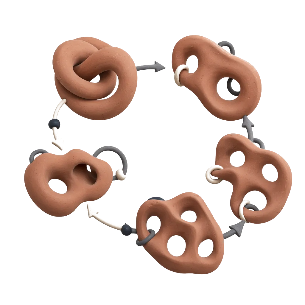
In this paper, we extend Sonon et al.’s method to Wang tiles in order to produce tile-based representations of microstructures intractable by the former methods [59, 61, 62], see Fig. 1. To this end, in Section 2, we review the fundamentals of the Wang tile concept and discuss, in detail, connectivity and mapping between vertex- and edge/face-based definitions of Wang tiles. Next, we outline Sonon et al.’s method [50, 52] and describe modifications necessary to accommodate generalized periodicity, see Section 3. Finally, equipped with the adapted procedure, we illustrate sample outputs of the procedure in two and three dimensions. We also compare three tile sets—two stochastic and a strictly aperiodic one—with the same cardinalities in terms of periodicity artefacts, complementing our previous study [62] that dealt only with the distribution of tile types.
2 Wang tiles
Wang tiles constitute the building blocks of the abstract concept used in this work. Albeit the shape of the tile domains can be any parallelogram (or a parallelepiped in 3D), for simplicity’s sake we assume only square (or cubic) domains in the sequel. All tiles from the tile set have compatibility codes attributed to their edges (faces), illustrated using colours in Figs. 1 and 2. These codes play the role of constraints during an assembly process of tile instances in a tiling—a portion of a plane (space) without any voids or overlaps; only tiles with the same codes on the abutting edges (faces) can be placed side by side. In addition, tiles can be neither rotated nor reflected during the assembly. Even though the last two requirements can be eliminated by modifying the definition of compatibility codes [63], we retain them for practical purposes since they preserve the orientation of the microstructure compressed within the tile set. The particular version of an assembly algorithm depends on the type of the tile set, discussed below.
Originally, the concept of Wang tiles was introduced in first-order predicate calculus as a visual surrogate to a decision problem of statements555A statement containing one existential () and two universal () quantifiers. [64, 65]. The initial conjecture that a whole plane can be covered only if a periodic tiling exists [64] was disproved shortly after [66], triggering the pursuit of the smallest tile set allowing for strictly aperiodic tiling of the plane, see the classical monograph [67] and [68] for historical overviews. This quest for the smallest set appears to be over; supported by an extensive computer-aided search, Jeandel and Rao [68] announced a set of 11 tiles over 4 codes for each edge orientation, stating that no smaller set exists.
2.1 Stochastic tile sets
Similar to applications in biology [69], physics [70], and computer graphics [71, 58], we use the concept only in its geometrical interpretation as a suitable formalism describing the mutual compatibility of small domains. Except for the comparison study in Section 4.1, we also limit ourself to the stochastic tile sets introduced by Cohen et al. [58]. Besides the fact that deterministic tilings of the aperiodic sets often exhibit locally ordered patterns, the stochastic sets offer higher flexibility in terms of design, i.e. choosing the number of tiles and codes and their distribution within the set666The limitations of aperiodic sets are especially critical in 3D, because only one aperiodic set of Wang cubes has been published to date [72]..
The assembly algorithm for stochastic sets works sequentially: an initially empty grid is traversed in a scanline [73] way; at each grid node, possible candidates compatible with previously placed tiles are identified in the set and one candidate tile is randomly chosen and placed; see the illustration in Fig. 3. Thus, the only requirement for the set design is that there is at least one tile (but optimally two or more to preserve the stochastic nature of the assembly) for every possible combination of codes on the upper and left-hand edges. In principle, the random choice from the subset can be replaced with an informed selection preferring e.g. different phase volume fractions in different regions of a domain according to a pre-generated Gaussian random field. This modification allows for correlations in the microstructure at length scales larger than the tile size. For the sake of brevity and without loss of generality, however, we use only the standard stochastic algorithm in this work.
The tiling concept’s ability to generate naturally looking patterns from a limited amount of samples—which proved highly appealing in computer graphics [58, 71]—stems from the reduced periodicity in tiling assemblies. This feature complies well with our ambition to replace a SEPUC-based description of random heterogeneous materials with its generalization that would allow for fast synthesis of stochastic microstructural samples or microstructure geometries for entire macroscopic domains.
The design of a compressed microstructural representation consists of two steps. First, the cardinality of the tile set and a particular distribution of edge (face) codes is chosen. This controls the frequency of tile occurrence in a tiling. Next, tile interiors are designed such that (i) the generated microstructure is continuous across the compatible edges and (ii) assembled tilings resemble the desired microstructure. Note that the latter requirement is not imposed on individual tiles. On the contrary, variability in the compressed representation is the main merit of the tiling concept. Tile interiors together with edge compatibility carry local microstructural characteristics, while the fluctuations over distances larger than the tile size are facilitated via the tile assembly algorithm.
2.2 Edge- vs. vertex-based tile definitions
Complementary to the edge-based specification introduced above, Wang tiles can be defined using vertex codes. Unlike the standard edge-based definition, the vertex-based definition allows for direct control of tile states across vertices, preventing pronounced repetitiveness when a visually distinctive microstructural feature falls into the vertex region [58]. To avoid this “corner problem”, Cohen et al. [58] proposed marking the tile vertices with an additional set of codes, essentially overlaying two tile set definitions. Subsequently, Lagae and Dutré [73] retained only vertex codes, reporting superior spectral properties for assembled patterns compared to edge-based sets with the same cardinality.
Albeit the two definitions yield the same cardinality of tiles () in the complete set, i.e. the set that contains all combinations of codes, they differ when it comes to minimal stochastic sets, i.e. sets that contain at least two tiles for each admissible code combination of already placed neighbouring tiles ( for edge-based sets vs. in the case of vertex-based ones). The difference is even more pronounced in three dimensions: a full face-defined set contains cubes compared to cubes in a vertex-defined set. Theoretically, Wang cubes can be also defined with edge codes in three dimensions; however, cardinality exceeds both the face- and vertex-based definitions without any known benefits.
Mapping vertex-defined tiles777The same procedure holds also for Wang cubes, where four vertices define one face code. to the original definition is straightforward: two vertex codes define one edge code. Hence all the above-mentioned design and assembly procedures directly apply to the vertex-based definition as well. In fact, the mapping provides an effortless way to produce a minimal stochastic edge-defined set with equal occurrence probability of each tile, the set characteristics sought for in [61]. On the other hand, because the mapping is injective only, it is generally not possible to map an edge-defined set to a vertex-based one.
2.3 Vertex analysis of a tile set
Here, we outline a tile set analysis capable of revealing the underlying vertex definition, if it exists. The motivation behind this analysis is the pragmatic question which arises when implementing generalized periodicity: If a particle intersects a tile boundary, what other tiles should it be copied to? While the answer is straightforward for a particle intersecting a tile edge, vertex overlap is more involved. A particle overlapping a vertex is carried to other tiles by both the horizontal and vertical edges. Because the particle overlapped a vertex in the original tile, its images overlap vertices of the other tiles as well. Consequently, these images are propagated further by the newly affected edge codes, see Fig. 4. Whether the particle is eventually copied to all vertices or appears only in a selected subset depends on the allocation of codes to individual tiles.
Assume an undirected graph888Instead of the standard vertex-edge nomenclature for a graph, we use node and arc terms in order to avoid confusion with similar geometrical notions related to Wang tiles. where each node represents the code on a particular half of an edge (either top/bottom for vertical or left/right for horizontal codes, resulting in two occurrences of each edge code) and each arc corresponds to a tile vertex. The graph is by definition bipartite, because each vertex connects horizontal and vertical codes, and represents a multigraph since there are usually more vertices with the same adjacent edge codes in the tile set. To answer the aforementioned question, we identify connected components of the graph using the Depth-First Search algorithm [74, Section 18.2]. Each independent sub-graph then corresponds to a distinct vertex code and the arcs pertaining to the sub-graph determine the vertices to which a vertex-overlapping particle will be propagated. See Fig. 5 for a comparison of three graphs pertinent to the tile sets depicted in Fig. 2. The subgraphs (if present) are plotted in distinct grey colours, which correspond to the colours of vertex codes shown in Fig. 2.
In three dimensions, a set of Wang cubes can be analysed analogously with only a minor modification: a graph node represents one corner of a cube face. Thus, each face code appears four times in the graph. In addition, cube edges with the same direction vector must be also classified, addressing the situation when a particle intersects a cube edge. The classification follows the exact same procedure as vertex identification in two dimensions, neglecting the codes on faces perpendicular to the analysed edges.
3 Tile design using level-set functions
As mentioned in Section 1.1, Random Sequential Adsorption (RSA)999Sometimes, the term Random Sequential Addition, e.g. [75], is used interchangeably. is one of the most frequent algorithms for generating particle packings and microstructural geometries. It follows the simple idea of throwing particles of an arbitrary shape into a given domain and keeping those that do not overlap with previously placed ones. In its original setting, however, the algorithm poses a critical drawback for higher volume fractions: the success rate for accepting the particle position rapidly decays in later stages, because the majority of the randomly selected positions collide with the already placed particles. Optimally, the remedy would be to sample the new particle position directly from a domain that is certified to result in a non-overlapping composition.
Several such remedies have been listed in Section 1.1. Here, we recall the approach of Sonon et al., because we have extended their methodology to Wang tiles. Sonon et al. [50, 51, 52, 53] adopted the implicit, level-set-based description of a microstructural geometry and demonstrated that it enables—in addition to the desired sampling from a valid domain loci—generating complex microstructural geometries (such as open and closed foams) in a unified framework, using suitable morphing operations. Moreover, both features are independent: if a particle packing is the desired output, the morphing operations can be neglected. On the other hand, any distribution of points or particles obtained by different packing methods can serve as the input for the morphing operations.
In the the remainder of Section 3, we revise individual steps from the Sonon et al.’s framework and introduce necessary modifications facilitating the compatibility constraints arising in the concept of Wang tiles. For the sake of clarity, all procedures are presented in the two-dimensional setting with comments about three-dimensional problems when necessary. Section 4 then presents both two- and three-dimensional results.
3.1 Generating particle packings
The original Sonon et al.’s approach [50] rests on describing the geometry of particle with a level-set function , which gives the signed distance of point from the nearest particle boundary (with negative values inside the particle), such that
[TABLE]
with the signed distance function given by
[TABLE]
Consequently, the zero iso-line of represents the particle boundary , as depicted in Fig. 6. Note that unlike many applications of the level-set method where the implicit geometry description evolves in time according to the Hamilton-Jacobi equation, see [76, and references therein], is computed for the given geometry of a particle and remains fixed.
Assume for now that we have domain that contains set of already placed particles and their geometry is encoded in a single level-set field ,
[TABLE]
see Fig. 7 for an illustration.
Knowing the radius of the smallest circumscribed circle as the only characterization of the new particle, overlaps with the existing particles can be readily prevented by sampling its centre from the domain
[TABLE]
After placing the new particle , the level-set field is updated with ,
[TABLE]
This procedure repeats until either a pre-defined stopping criterion (e.g. a desired volume fraction) is met or .
To increase the volume fraction that can be achieved with this procedure, two additional restrictions can be posed on the admissible subdomain . First, a maximal distance from existing particle boundaries can be added to Eq. (4), preventing too large gaps between particles. (If requested, a minimal distance between two particles can be further enforced as well.) Second, to prevent locally jammed states with large interparticle gaps, an additional field storing the shortest distance to the surface of the second nearest particle can be included in Eq. (4) and limited from above with , see [50] for additional details. With all these constraints in action, Eq. (4) takes the form
[TABLE]
Enforcing periodicity of the packing is also straightforward: upon placement of a new particle, the domain level-set field is also updated with the particle’s periodic images (eight in 2D; recall the grid in Fig. 8, and 26 in 3D).
3.1.1 Extension to Wang tiles
Compared to generating PUCs, the additional compatibility constraints among individual Wang tiles necessitate several modifications in the original Sonot et al.’s algorithm to generate continuous microstructural morphology of a tile set. For the Poisson discs distribution, Lagae and Dutré [77] modified the Dart Throwing algorithm by partitioning tile domains into separate regions pertinent to vertices, edges, faces, and tile interiors, and filling the regions sequentially, starting with the vertex regions. Here we present a different approach better suited to packing particles of different sizes and shapes that processes all tiles simultaneously and does not require a priori partitioning of tile domains.
As we use a level-set field defined on a regular grid for each tile in the tile set . For each tile in a pre-processing stage, we identify potential neighbouring tiles and store their indices in a grid ( or in two or three dimensions, respectively), see Fig. 8, which will be used later in the updating phase.
For further description, we define a copy-inducer as a geometrical entity that is responsible for inducing particle copies to other tiles. Hence, a copy-inducer can be either a vertex, edge, face, or formally the tile itself and is related to a code identified in Section 2.3. The particular type of the copy-inducer stems from particle’s intersections with a tile boundary (if a particle does not intersect a boundary, the tile is the copy-inducer, indicating that no copy is necessary. If a particle intersects one edge, the edge is the copy-inducer, and so on).
Modification 1: Update
The main structure of the modified algorithm follows the original one. After sampling a particle location from , which yields tile and centre where the new particle will be placed, the particle’s intersections with the boundary of are determined, and—based on the intersections—a copy-inducer is identified. Images of the particle are subsequently copied to the relevant tiles following the matching codes on the corresponding copy-inducers. A level-set field of the whole set is then updated tile-wise as described below.
For each tile, we sequentially loop over all tile positions in the neighbours grid shown in Fig. 8 (including the centre position as well) and check each of the potential tiles at that position for a new particles added in the current step. If any, the central tile’s level-set field is updated according to Eq. (5). Clearly, a new particle can appear several times in the same place. To avoid duplicated calculations, we set up a bookkeeping structure that records which copy-inducer in the neighbouring grid was already used during the update and run only the unperformed updates, see Fig. 8.
Two implementation approaches are possible at this stage: (i) is computed anew for each tile and position in the bookkeeping structure, or (ii) provided that is represented with discrete values on a regular grid, is precomputed for an auxiliary domain/patch aligned with the particle centre before any update and this field is then reused for all particle instances. Moreover, we combine both approaches with the pre-screening acceleration proposed in [50] that resorts to computing potentially demanding surface-distance functions only when the value of a circumscribed circle/sphere—which is fast and easy to calculate—is less than the actual value for a given .
While the pre-screening acceleration is significant in all cases, the benefits of a precomputed patch depend mainly on the patch size relative to the particle circumscribed radius, the field resolution, and the cardinality of the tile set. Especially in the later stages of the algorithm, when only relatively small parts of are updated, pre-computing a patch for a particle that is not copied to other tiles might cause unnecessary overhead. Therefore, we use the patch approach only for particles with either vertex, edge, or face copy-inducers.
For the three-dimensional set of 16 cubes used in Section 4.3 with ellipsoidal particles of circumscribed radius , the patch pre-calculation delivered 10% saving in computational time on average. Note also that the multi-query problem of finding the shortest distance to a particle boundary from a set of points is trivially parallelizable, changing the trade-off between patch pre-computations and direct calculations with available threads.
When all tiles are updated, the algorithm proceeds with identifying for the next particle.
Modification 2: Artificial level-set field
Definition of the admissible domain must also be modified for Wang tiles; particle centres cannot be sampled directly from obtained from . The reason for this is that the near-boundary parts of each tile must be informed about the interiors of related tiles in order to prevent insertions similar to the one depicted in Fig. 9a, where a copied instance of a newly placed particle collides with interior particle(s) of other tiles.
The problem arises only when a particle image is added to a copy-inducing entity with the same orientation as the actual inducer (left-hand side edges in Fig. 9a); particles copied to the opposite copy-inducers automatically meet the non-overlap requirement thanks to the first update modification described above.
To avoid this problem, we replace in Eq. (4) or Eq. (6)101010Recall that the tile set domain substitutes a generic in both equations from Section 3.1.1 onwards. with a modified field which is equal to except for boundary regions, whose width is dictated by the radius of the circle/sphere circumscribed to the current particle. Each boundary region is then constructed as a point-wise minimum over all regions related to the same copy-inducers with the same code and the same orientation; see Fig. 9c. This construction propagates the close-boundary state across relevant tiles and thus prevents overlapping insertions similar to the one depicted in Fig. 9a. Note that a similar modification is not required for because all information necessary to prevent the collisions is already contained in .
Modification 3: Breaking regular grid
The level-set field is typically implemented on a regular grid and the particle centres thus end up aligned with the grid. To break this artificial ordering, after sampling a new particle centre, we check whether the surrounding points belong to . The belonging points then define quadrants/octants in which the particle can be moved freely. We generate a random shift within these quadrants/octants and update the particle centre accordingly. However, this modification is possible only if the grid spacing is sufficiently small compared to the particle size; otherwise, the implicitly assumed linear approximation of is inaccurate and might result in particle intersections at intermediate locations.
The modifications described above are sufficient for extending the original Sonon et al.’s level-set-based packing algorithm to the concept of Wang tiles. Note that all control variables, e.g. particle radius or minimal and maximal distances and , can change while the algorithm operates. For instance, to achieve denser packings for multi-modal particle size distributions, it is preferential to start placing large particles first and sequentially proceed to the smaller ones.
Nonetheless, our extension inherits the weakness of the original algorithm when it comes to particles whose shapes are significantly different than their circumscribed circle/sphere, e.g. prolonged ellipsoids. In particular, the more the particle volume deviates from the volume of the circumscribed sphere, the less dense the final packing can be. While the geometry of the already placed particles is described exactly with (up to inaccuracies due to grid spacing in ), the newly placed particle is represented only approximately during selection of a centre, yielding a pessimistic estimate of mutual intersections. The potential remedy is to translate the particle centre right after sampling according to some heuristic rule aimed at producing denser packings; however, we leave this issue unaddressed in this paper.
3.2 Morphing operations
The acceleration of RSA by adopting the level-set approach is attractive on its own; however, the main appeal of the Sonon et al.’s level-set framework is the elegance with which complex microstructures can be generated. As the simplest example, adding a constant to enables (i) fine-tuning of particle volume fractions, (ii) smoothing of sharp corners of polyhedral particles, and (iii) particle coating, e.g. for defining the Interfacial Transition Zone.
Combinations of and permit rendering interparticle bridges and controlled Voronoï-like tessellations; see [50], where these morphing operations were used to mimic microstructural geometry of clay/sand mixed soils and irregular masonry. Considering also the shortest distance to the boundary of the third nearest particle , Sonon et al. [52] demonstrated that their framework can produce highly adjustable models of foam-like microstructures, including features such as a smooth transition from open to closed foams, concavity of foam ligaments, their coatings and hollow interiors, and variable thickness of foam ligaments and cell walls.
As in Section 3.1, we present only the essentials of generating foam-like microstructures and introduce necessary modifications. The reader is referred to [50, Section 4] and [52, Sections 3 and 4] for details regarding the above-mentioned local adjustments, since they remain unchanged.
Assume we have at our disposal all three fields , , and , containing the shortest distance to the boundary of three nearest particles (either computed a posteriori for a given particle assembly or already tracked during the packing algorithm).
In a manner similar to classical Voronoï tessellation, where a domain is partitioned by boundaries that have the same distance to the two closest seeds, thresholding the modified difference
[TABLE]
yields a closed-cell, foam-like geometry with indirectly controlling the thickness of foam cell walls. In the same spirit, the centrelines of the open-foam ligaments can be viewed as loci with the same distances to the boundary of three nearest particles; hence thresholding
[TABLE]
produces open-foam ligaments with governing their thickness. Finally, combining Eqs. (7) and (8)
[TABLE]
allows for more realistic geometries with material concentration at wall intersections, see Fig. 10.
It is critical when extending the original framework to Wang tiles, with respect to the morphing procedures, to ensure that all three fields are continuous across the relevant tile edges/faces. As illustrated in Fig. 11, copying particle images introduced in the previous subsection is insufficient in this regard. To guarantee the required continuity, we define a wider domain margin as a subdomain related to individual copy-inducers. Instead of computing intersections with a tile boundary, we compute them for a virtual inset boundary (inset by is usually enough) and copy the particles according to the virtual copy-inducers. Consequently, wider portions of tile domains are restrained near boundaries, resulting in restored continuity. This modification is also reflected in the construction of auxiliary field .
4 Results
4.1 Comparison of 16-tile sets
First, we compare the periodicity reduction in three planar sets depicted in Fig. 2, which have the same cardinality but different tile definitions. We supplement our earlier observations [62] regarding suppressed artificial periodicity compared to PUC-based reconstructions and better fitness of stochastic tile sets over their aperiodic counterparts. Namely, we consider: (C16) an edge-based stochastic set over four colours,111111This set corresponds to the set reported in [58]. (V16) a vertex-based stochastic set over eight colours, and (A16) the aperiodic Ammann’s set [57] over 12 colours121212For the aperiodic assembly, we used the substitution rule from [78]..
Assuming ergodicity of a microstructure, we quantify the artificial periodicity in the tiling assemblies by means of the secondary peaks in the two-point probability function [4]. states the chance of finding two points separated by in the same phase. Hence, attains its maximum at , where it equals the volume fraction of a chosen phase. For microstructures without any internal ordering, with because two sufficiently distant points are uncorrelated. On the other hand, if a microstructure is composed of a repeating (SE)PUC, exhibits secondary peaks having the same magnitude as at nodes of a regular grid whose spacing corresponds to the (SE)PUC size. Thus, in the intermediate case of Wang tiling, the magnitude of secondary peaks indicates the remaining artificial ordering in the reconstructed microstructure, see [59, 62] for details. For computing , we used the Fast Fourier Transform (FFT) instead of random sampling, because the bias in the statistics caused by the implicit periodicity introduced with FFT is negligible for reasonably large microstructural realizations [79]. Recall also that the two-point probability function , widely used for statistical quantification of material microstructures, e.g. [4], is the inverse Fourier Transform image of the power spectral density (or its estimate via periodogram) traditionally used in the Computer Graphics community, e.g., [58, 71, 77].
For each of the three tile sets we ran the presented algorithm 25 times and thus generated 25 different tile set morphologies. Aiming at capturing the artificial periodicity related to the limited number of edge codes and tiles, we resorted to the simplest set-up with circular inclusion of a fixed radius in order to minimize the influence of particle shapes. In addition, we prevented the particles from overlapping tile vertices in order not to favour the vertex-based tile set a priori131313From Fig. 5 it follows that a particle will be copied to all tiles if it overlaps any vertex for the A16 and C16 tile sets.. The level-set fields of each unit-size tile () were discretized using a regular grid comprising points. Finally, we posed two constraints, and , on , recall Eq. (6).
We assembled 100 microstructural realizations, i.e. tilings, containing tiles for each tile set and tile morphology and computed statistics for the inclusion phase. Cross-sections of along the coordinate are plotted in Fig. 12 for the tile sets considered. As expected, the secondary peaks appear at loci with integer coordinates. Excluding the primary peak, we picked the second highest extreme normalised against the averaged asymptotic value for each realisation and plotted the obtained data with box-and-whisker diagrams in Fig. 13.
While the Ammann’s tile set A16 seems promising locally—note the suppressed secondary peaks at and in Fig. 12c—its deterministic aperiodic structure leads to pronounced secondary extremes in other regions, e.g. . This observation corroborates our previous conclusions, based solely on the distribution of individual tiles within tilings, that strictly aperodic sets such as the Ammann’s or Culik’s set considered in [62] lead to higher secondary peaks than stochastic sets [58] with the same cardinality, which feature more uniform secondary peaks. Figs. 12 and 13 clearly show that, out of the two stochastic sets, the vertex-based definition performs better as expected, even despite the prevented vertex overlaps. This superiority of vertex-based tile sets in two dimensions is further supported by additional results comparing vertex- and edge-based sets comprising 81 tiles, see Fig. 13.
4.2 2D example
Second, we present an example of a two-dimensional microstructure based on polygonal particles. The geometry of each particle was derived from an originally regular, randomly-oriented polygon with the number of vertices being sampled from a normal distribution with the mean value and the standard deviation , , and rounded to the nearest integer. The angle between two rays connecting the particle centre and neighbouring vertices was perturbed with a value randomly chosen from . Finally, each vertex was placed on its corresponding ray at a distance sampled from (and capped by ) relative to the particle’s circumscribed radius.
Following the outcomes of Section 4.1, we picked the vertex-based set with 16 tiles depicted in Fig. 2b. Similarly to the previous set-up, the size of each tile was and the corresponding level-set fields were discretized using a regular grid comprising points. The initial value of the circumscribed radius was set to . After 40 algorithm steps, the radius was increased to , and eventually we reduced it to 0.06 after next 60 steps. The number of algorithm steps and related radii were chosen randomly to illustrate the algorithm’s control options. Only the first two constraints on from Eq. (6) were posed. We fixed the minimal particle distance at ; the maximal distance was set to in the first 50 steps and decreased to later. The width of the virtual boundary inset was kept constant at .
Fig. 14 depicts a composed view of the resulting particle assembly and the related closed-cell, foam-like microstructural geometry obtained by considering and in Eq. (9).
4.3 3D example
Finally, we demonstrate a three-dimensional output of the algorithm for a set of 16 Wang cubes with two codes for each face orientation uniformly distributed in the set.
Again, we used centred tile domains of a unit size discretized with a grid of points. For the packing part of the algorithm, we considered ellipsoidal particles with a random orientation and a fixed circumscribed radius . The ratio between the middle and the major semi-axes lengths was sampled from a uniform distribution ; the minor to the major semi-axes length ratio was randomly generated from . The admissible domain at each algorithm step was dictated both by and with constraints , , and in Eq. (6). Since we aimed at modelling a foam-like microstructure, the width of a virtual inset boundaries was set to .
The final microstructure was obtained by performing the morphing operations according to Eq. (9) with and . For the sake of brevity, we do not show individual Wang cubes, and we plot only a microstructural sample comprising tiles in Fig. 15.
4.4 Computational cost
Our extension inherits the complexity of the Sonon et al.’s method [50, 52], as shown in Fig. 16. However, the actual time needed to generate particle packings or complex morphologies depends on several factors. While the impact of the grid resolution is straightforward (computational time scales linearly with the number of grid points), the effect of other factors such as particle shape and compatibility constraints due to different definitions of a tile set is less obvious.
To illustrate the influence of these factors, wall-clock time for several settings is plotted in Fig. 16. Tile sets considered for the analysis are the two-dimensional ones used in Section 4.1 and the three-dimensional sets from Section 4.3; in addition, a PUC was included in the comparison as a trivial case of a tile set. For all settings, tile domains of unit size were discretized with grid points in two and grid points in three dimensions. The circumscribed radius of particles was set to for two-dimensional and for three-dimensional problems. The algorithm was terminated once the desired number of placed particles was achieved. Computational time141414All computational times are reported for a workstation equipped with an Intel® Xeon® E31280 3.50 GHz processor and 16 GB RAM running Windows 10 version 1903. The algorithm was implemented in the latest standard of C++ language (C++17), relying on parallel algorithms from the C++’s Standard Template Library. for each setting was measured times.
Interestingly, albeit of the same cardinality, individual tile sets from Section 4.1 exhibit significantly different computational times. This is due to the distribution of edge codes within a set, because a larger part of the tile set domain must be updated with each particle copy in sets with fewer codes, recall Section 3.1.1. Note that Ammann’s set with six codes for both horizontal and vertical edges behaves nearly the same as PUC.
Computational time related to the morphing operations depends on the operational mode of the algorithm. If the algorithm is used for both packing and morphing at the same time, the level-set fields used during the particle packing phase can be directly utilized for the morphing operations. On the other hand, when the morphing part runs separately, all the distance fields must be calculated again. Yet this recalculation is typically faster than the packing because all copies and compatibility constraints are already taken into account; for instance, generating the particle packing for the microstructure presented in Section 4.3 took 1,280 s while the recalculation needed for the morphing operations finished in 420 s.
5 Summary
In this work, we have extended Sonon et al.’s level-set based framework [50] to the microstructural models based on the formalism of Wang tiles. The extension enables generating compressed representations of complex microstructural geometries such as open and closed foams or cells, which have been nearly impossible [62] or very expensive [59] to generate for Wang tiles to date.
Advancing from the standard Periodic Unit Cell to the generalized periodicity of Wang tiles necessitated several modifications of the original algorithm that addressed difficulties originally not encountered in the case of PUC. Driven by the geometrically-motivated question of where a vertex-overlapping particle should be copied to, we have come up with a simple procedure based on a graph analysis capable of revealing the underlying vertex definition of a tile set, if present. We have also demonstrated that a straightforward copying of boundary-intersecting particles according to the edge and vertex codes is insufficient for preventing spurious particle overlaps because the information about the interior of a tile is not automatically communicated across individual tiles. As a remedy, we have introduced an artificially updated level-set field that facilitates this necessary communication. The width of the updated region in this field is dictated by the required final geometry. If only a particle distribution is to be generated, the width equal to the particle radius suffices. On the other hand, if foam-like microstructures are desired, the virtual boundary inset by is necessary in order to preserve continuity of the level-set fields and across tile edges, resulting in the updated region of width .
Additionally, we have devised two minor modifications, one capable of breaking a regular underlying grid of possible particle centres by introducing their random shifts within an admissible region, the other accelerating the updates by pre-computing on a patch. The importance of the latter modification grows with higher resolutions and larger cardinality of a tile set.
Having a universal framework for generating Wang tile morphologies at our disposal, we have supplemented our previous comparison of strictly aperiodic and stochastic tile sets [62] and confirmed the superiority of vertex-defined tile sets in suppressing artificial periodicity in assembled microstructural samples. Given the same cardinality of the edge- and vertex-based tile sets in two dimensions, we recommend using the latter. On the other hand, the same comparison in three dimensions is more subtle and the choice should be always a compromise between available computational resources and required periodicity reduction, following e.g. the approximate formula proposed in [59].
Admittedly, the presented modification inherits certain limitations posed by the original framework; namely, it provides only indirect control of a resulting microstructural geometry and no spatial statistics are involved in the particle placing process. Albeit addressing these limitations remained out of the scope of this work, ideas conceptually similar to [10], i.e. optimizing the particle positions a posteriori to minimize the discrepancy between target and computed spatial statistics, could be potentially applied to steer the generated microstructure to the desired statistics.
Albeit our extension features linear complexity as in the original Sonon et al.’s framework, the generalized periodicity brings increased computational cost compared to PUC generation, see Section 4.4. Recall though that tile-based compression is intended primarily for generating numerous stochastic realizations with arbitrary sizes. Thus, more time can be spent on preparing the initial microstructure because the increased cost will be amortized later during repeated use of the same compression.
Our current focus is on developing a robust finite element discretization tool that would enable meshing both outputs of the framework, i.e. analytical geometries of particulate microstructures and complex geometries implicitly defined via level-set fields and processed with the marching-cube algorithm. In both cases, special attention will be paid to ensuring topological and geometrical compatibility of the resulting finite-element meshes across the corresponding faces/edges.
Acknowledgment
M. Doškář, J. Novák, and D. Rypl acknowledge the endowment of the Ministry of Industry and Trade of the Czech Republic, project No. FV10202. This research was performed at the Center of Advanced Applied Sciences (CAAS), financially supported by the European Regional Development Fund (project No. CZ.02.1.01/0.0/0.0/16_019/0000778). M. Doškář was also partially supported by the Grant Agency of the Czech Technical University in Prague through student project No. SGS18/036/OHK1/1T/11, and J. Zeman received partial support from Czech Science Foundation project No. 17-04301S. We thank Stephanie Krueger for helpful comments and proof-reading the manuscript.
The reference list from the paper itself. Each links out to its DOI / PubMed record.
- 1Nguyen et al. [2011] V. P. Nguyen, O. Lloberas-Valls, M. Stroeven, L. J. Sluys, Homogenization-based multiscale crack modelling: From micro-diffusive damage to macro-cracks, Computer Methods in Applied Mechanics and Engineering 200 (9-12) (2011) 1220–1236, ISSN 00457825, doi: 10.1016/j.cma.2010.10.013 . · doi ↗
- 2Barchiesi et al. [2019] E. Barchiesi, M. Spagnuolo, L. Placidi, Mechanical metamaterials: a state of the art, Mathematics and Mechanics of Solids 24 (1) (2019) 212–234, ISSN 1081-2865, 1741-3028, doi: 10.1177/1081286517735695 . · doi ↗
- 3Matouš et al. [2017] K. Matouš, M. G. Geers, V. G. Kouznetsova, A. Gillman, A review of predictive nonlinear theories for multiscale modeling of heterogeneous materials, Journal of Computational Physics 330 (2017) 192–220, ISSN 00219991, doi: 10.1016/j.jcp.2016.10.070 . · doi ↗
- 4Torquato [2002] S. Torquato, Random heterogeneous materials: microstructure and macroscopic properties, no. 16 in Interdisciplinary applied mathematics, Springer, New York, ISBN 0-387-95167-9, 2002.
- 5Nguyen et al. [2017] T. Nguyen, J. Yvonnet, M. Bornert, C. Chateau, F. Bilteryst, E. Steib, Large-scale simulations of quasi-brittle microcracking in realistic highly heterogeneous microstructures obtained from micro CT imaging, Extreme Mechanics Letters 17 (2017) 50–55, ISSN 23524316, doi: 10.1016/j.eml.2017.09.013 . · doi ↗
- 6Lloberas-Valls et al. [2011] O. Lloberas-Valls, D. Rixen, A. Simone, L. Sluys, Domain decomposition techniques for the efficient modeling of brittle heterogeneous materials, Computer Methods in Applied Mechanics and Engineering 200 (13-16) (2011) 1577–1590, ISSN 00457825, doi: 10.1016/j.cma.2011.01.008 . · doi ↗
- 7Akbari Rahimabadi et al. [2015] A. Akbari Rahimabadi, P. Kerfriden, S. Bordas, Scale selection in nonlinear fracture mechanics of heterogeneous materials, Philosophical Magazine 95 (28-30) (2015) 3328–3347, ISSN 1478-6435, 1478-6443, doi: 10.1080/14786435.2015.1061716 . · doi ↗
- 8Lloberas-Valls et al. [2012] O. Lloberas-Valls, D. Rixen, A. Simone, L. Sluys, Multiscale domain decomposition analysis of quasi-brittle heterogeneous materials, International Journal for Numerical Methods in Engineering 89 (11) (2012) 1337–1366, ISSN 00295981, doi: 10.1002/nme.3286 . · doi ↗