Dispersion forces stabilise ice coatings at certain gas hydrate interfaces which prevent water wetting
Mathias Bostr\"om, Robert Corkery, Eduardo Lima, Oleksandr Malyi,, Stefan Y. Buhmann, Clas Persson, Iver Brevik, Drew F. Parsons, Johannes, Fiedler

TL;DR
This study reveals that dispersion forces create thin ice films on gas hydrate particles, affecting their stability, buoyancy, and interactions with water, with implications for climate, energy, and planetary science.
Contribution
It demonstrates that dispersion forces induce ice coatings on gas hydrates, influencing their physical behavior and interactions at interfaces, a novel insight into hydrate stability.
Findings
Ice films alter hydrate buoyancy and contact with water.
Dispersion forces influence hydrate growth and gas leakage.
Ice coatings impact hydrate stability in natural environments.
Abstract
Gas hydrates formed in oceans and permafrost occur in vast quantities on Earth representing both a massive potential fuel source and a large threat in climate forecasts. They have been predicted to be important on other bodies in our solar systems such as Enceladus, a moon of Saturn. CO-hydrates likely drive the massive gas-rich water plumes seen and sampled by the spacecraft Cassini, and the source of these hydrates is thought to be due to buoyant gas hydrate particles. Dispersion forces cause gas hydrates to be coated in a 3-4 nm thick film of ice, or to contact water directly, depending on which gas they contain. These films are shown to significantly alter the properties of the gas hydrate clusters, for example, whether they float or sink. It is also expected to influence gas hydrate growth and gas leakage.
Click any figure to enlarge with its caption.
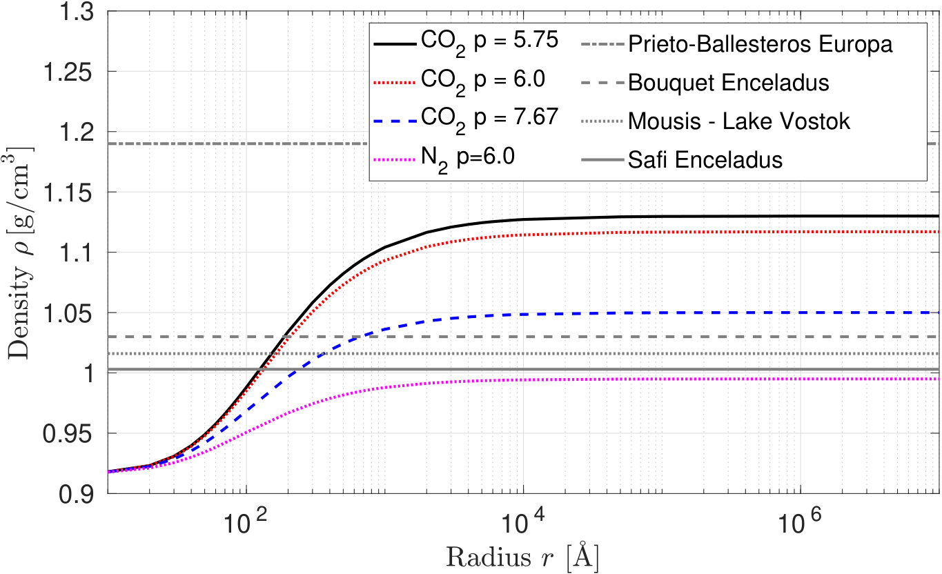 Figure 1
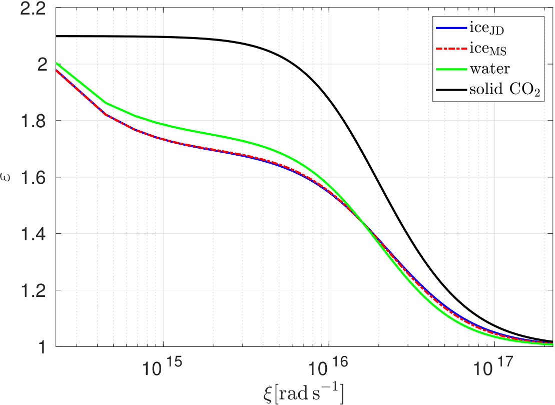 Figure 2
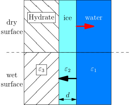 Figure 1
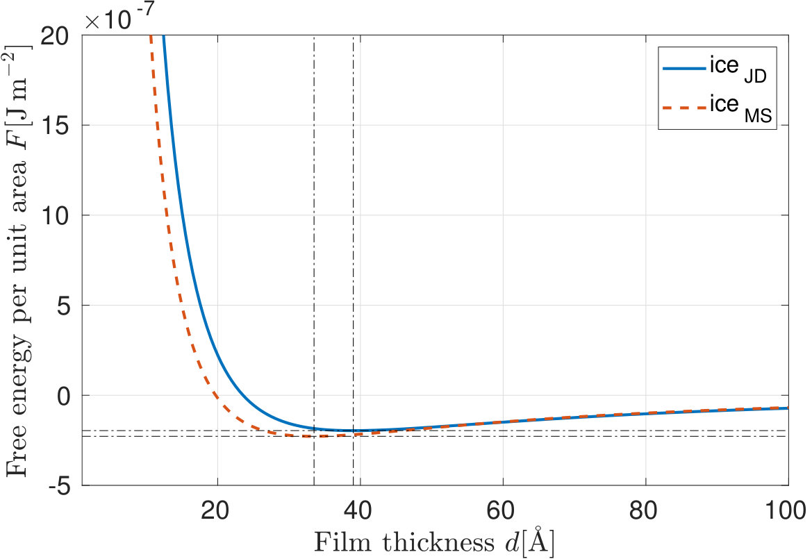 Figure 4
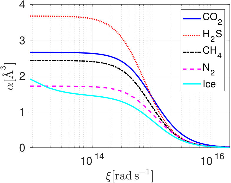 Figure 5
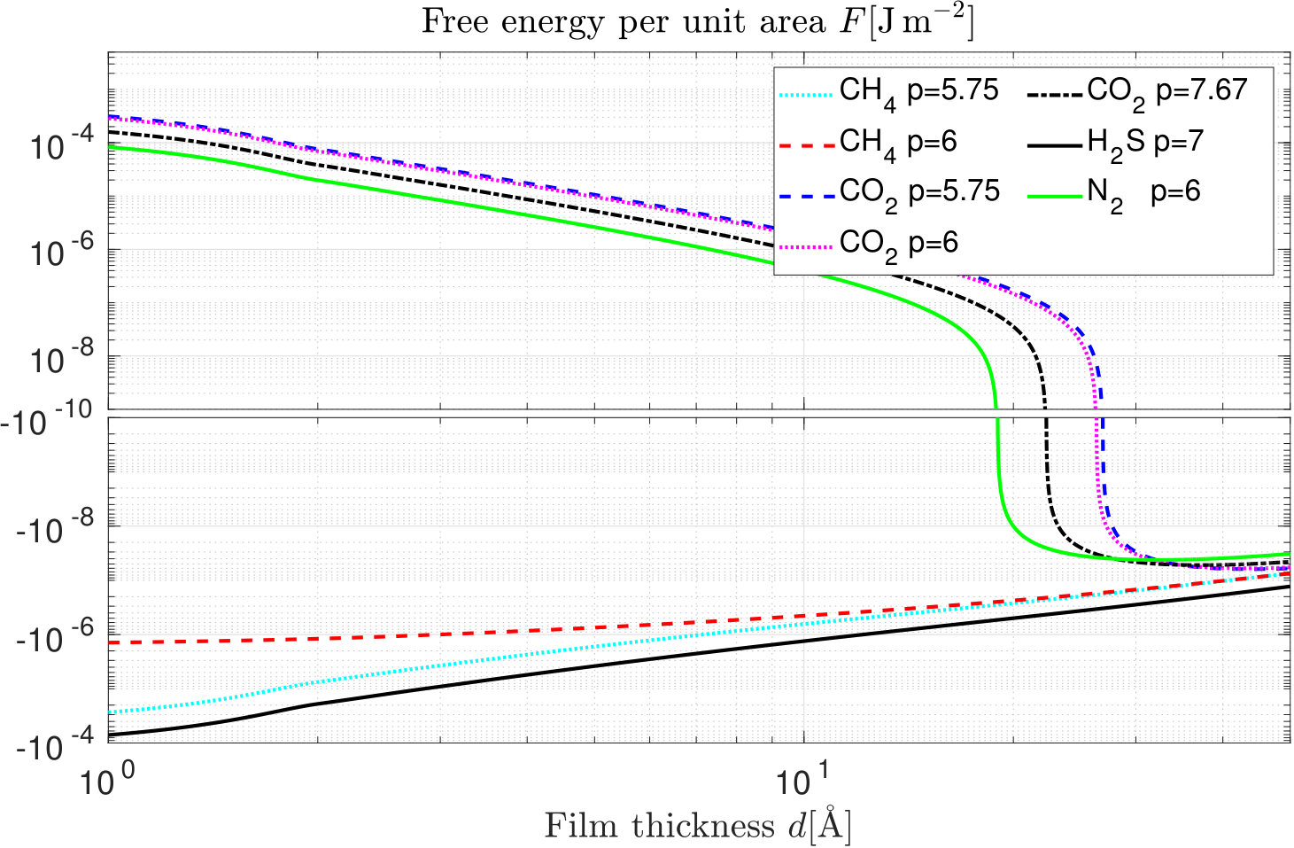 Figure 6
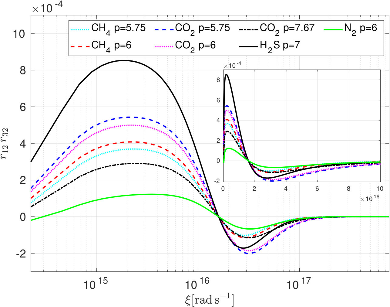 Figure 7
Peer Reviews
No public reviews on file for this paper yet. If you reviewed it on a platform where reviews are public (OpenReview, ICLR, NeurIPS, ICML), you can paste yours below so the community can read it here.
Videos
No videos yet. Explain this paper in a talk, walkthrough, or lecture? Add one.
Dispersion forces stabilise ice coatings at certain gas hydrate interfaces which prevent water wetting
M. Boström
Department of Energy and Process Engineering
Norwegian University of Science and Technology
NO-7491 Trondheim, Norway
[email protected] \AndR. Corkery
Surface and Corrosion Science
Department of Chemistry
KTH Royal Institute of Technology
SE 100 44 Stockholm, Sweden
[email protected] \AndE. R. A. Lima
Programa de Pós-graduação em Engenharia Química
Universidade do Estado do Rio de Janeiro
CEP 20550-013, Rio de Janeiro RJ, Brazil \AndO. I. Malyi
Centre for Materials Science and Nanotechnology
Department of Physics
University of Oslo
P. O. Box 1048 Blindern
NO-0316 Oslo, Norway \AndS. Y. Buhmann
Physikalisches Institut
Albert-Ludwigs-Universität Freiburg
Hermann-Herder-Str. 3
79104 Freiburg, Germany \AndC. Persson
Centre for Materials Science and Nanotechnology
Department of Physics
University of Oslo
P. O. Box 1048 Blindern
NO-0316 Oslo, Norway \AndI. Brevik
Department of Energy and Process Engineering
Norwegian University of Science and Technology
NO-7491 Trondheim, Norway \AndD. F. Parsons
School of Engineering and IT
Murdoch University
90 South St
Murdoch, WA 6150, Australia
[email protected] \AndJ. Fiedler
Physikalisches Institut
Albert-Ludwigs-Universität Freiburg
Hermann-Herder-Str. 3
79104 Freiburg, Germany
[email protected] Centre for Materials Science and Nanotechnology, Department of Physics, University of Oslo, P. O. Box 1048 Blindern, NO-0316 Oslo, NorwayApplied Physical Chemistry, KTH Royal Institute of Technology, SE 100 44 Stockholm, SwedenFreiburg Institute for Advanced Studies, Albert-Ludwigs-Universität Freiburg, Albertstr. 19, 79104 Freiburg, GermanyCentre for Materials Science and Nanotechnology, Department of Physics, University of Oslo, P. O. Box 1048 Blindern, NO-0316 Oslo, Norway
Abstract
Gas hydrates formed in oceans and permafrost occur in vast quantities on Earth representing both a massive potential fuel source and a large threat in climate forecasts. They have been predicted to be important on other bodies in our solar systems such as Enceladus, a moon of Saturn. CO2-hydrates likely drive the massive gas-rich water plumes seen and sampled by the spacecraft Cassini, and the source of these hydrates is thought to be due to buoyant gas hydrate particles. Dispersion forces cause gas hydrates to be coated in a 3-4 nm thick film of ice, or to contact water directly, depending on which gas they contain. These films are shown to significantly alter the properties of the gas hydrate clusters, for example, whether they float or sink. It is also expected to influence gas hydrate growth and gas leakage.
K****eywords Gas hydrates Interfacial ice formation Buoyancy Lifshitz interactions Dispersion forces
1 Introduction
Gas hydrates are systems consisting of water and gas molecules forming a solid ice structure. Such systems can naturally be found in ice-cold water [1]; in particular, they can occur in permafrost [2], sediments [3], and below the oceans in the seabed [4]. For the latter, there are particularly interesting examples where gas hydrates are considered important in connection with planetary processes and the implications for life. The aqueous ocean-bearing moons Europa and Enceladus are perhaps the best examples in our solar system beyond Earth where gas hydrates are formed in salty oceans that are favourable for life [5]. On Mars, methane distribution is associated with subterranean water, implying the presence of methane hydrates [6]. On Enceladus giant plumes of erupted gases are observed and the composition directly measured to be water, salts and volatile gases including CO2, CO, N2, H2S and methane [7, 8]. Several hypotheses consider gas hydrates to be important for the creation of volatile enriched plumes and for the composition of ice layers beneath and/or entrained into, or sprayed onto the outer surface of Enceladus [9, 10, 11]. In particular, type II gas hydrates on Enceladus and Europa are calculated to be less dense than water and can float in their respective oceans. They are thereby available for incorporation into the overlying thick ice layer of each icy moon. Type I CO2 hydrates are at a density where their positive or negative buoyancy is uncertain [12, 13, 14, 15, 9]. However, if a layer of water ice forms on these gas hydrates in the presence of ice cold liquid water, then the growth of such hydrate crystals may be limited by the capping effect. This may have an impact on their buoyancy, and thus on the hypothesized composition of the ice layers in Enceladus and Europa, with obvious implications for the composition of their plumes and their potential to sample the underlying oceans and any harboured life.
On Earth, methane hydrates occur naturally and in engineered situations. Large reservoirs of methane hydrates occur in sediments of deep oceans basins, at shallower depths in the sediments of arctic sea shelves, and in deep permafrost regions. In all these cases, the understanding of whether a layer of ice forms on the hydrate has implications for exploration and production of fossil fuels, and also for understanding the potential for methane contribution to greenhouse gases as the planet becomes warmer.
In all of the contexts above, hydrates are usually surrounded by ice cold water. Depending on the gas hydrate structure with respect to contributions and volume fractions, it turns out that some hydrates form an ice interface to water, whereas others do not. The latter have a wet surface. The ones with a gas hydrate-ice interface may be considered to have a dry surface. The prediction of the wet or dry surface cannot be made easily. In the present paper we address this issue by considering a planar three-layer system, as depicted in Fig. 1, namely a gas hydrate layer, an ice sheet, and a water layer. Thus, we assume that initially all hydrates are covered by an ice interface. We estimate the Casimir force acting on the outside at the ice-water interface, i.e., the pressure acting on the system. Depending on the sign of the Casimir force, it will work towards growth or melting of the thin ice sheet. We assume that the temperature is at the triple point of water. An attractive pressure acting on the ice layer thus results in a melting of the ice sheet [16, 17, 18]. It will simply vanish. This kind of consideration is not new. In the past, ice melting at the triple point with a nano-sized film of water was discussed [19]. It was found that a thin water film is energetically favourable up to a certain thickness where it has an energy minimum [19, 20, 21, 22, 23]. The inclusion of retardation resulted in incomplete melting while a non-retarded approximation predicted complete melting for an ice surface at the triple point of water [19].
Here we apply Lifshitz theory to estimate the energy of the hydrate-ice-system as a function of ice thickness, and show that for some gas hydrates the ice film is stabilised at a thickness of 3-4 nm, while for other gas hydrates the ice film is unstable, resulting in direct wetting.
2 Materials and Methods
2.1 Dispersion forces between solid bodies
The Casimir interaction energy (also known as Lifshitz free energy) per unit area between material 1 (water) with dielectric function and material 3 (gas hydrate), , separated by the distance across medium 2 (ice), as depicted in Fig. 1 can be written at temperature as [24, 25, 26, 27]
[TABLE]
where (TX=TM, TE) denotes the trace over the scattering for transverse magnetic (TM) and transverse electric (TE) Green’s function. This fundamental solution comes from the vector Helmholtz equation for the electric field. The primed sum denotes that the term is weighted by a factor one half. At finite temperature these functions are evaluated at the discrete Matsubara frequencies [28]. The systems in this study, as mentioned, are all studied at the triple point of water. For the considered three layer system, the traces over the scattering Green’s functions, including multiple reflection in the center layer, can be written (in cgs units) as
[TABLE]
with , and the Fresnel reflection coefficients are
[TABLE]
for TM waves and
[TABLE]
for TE waves. We have introduced the imaginary part of the transverse wave vector . We assume nonmagnetic media.
2.2 Material Modelling
Dielectric functions (at imaginary frequencies) were taken from Elbaum and Schick [19] using the data from Daniels [29] and labeled by iceJD and from Seki et al.[30] (iceSM) for ice () and from Elbaum and Schick[19] for water (). These dielectric functions are for a system at the triple point of water, close to zero degrees Celsius at low pressure. The final results for ice melting [19, 20, 21, 22, 23, 31, 32] and water freezing [33, 34] are sensitive to the dielectric functions of ice and water since these are extremely similar when the water is in equilibrium with the ice. We show in Fig. 2 the dielectric functions for crystalline CO2, water and ice.
A model for the dielectric function of a gas hydrate () is derived using the Lorentz-Lorenz model [35] with the mixing scheme specifically for gas hydrates taken from Bonnefoy et al.[36, 37]
[TABLE]
with
[TABLE]
which means that the dominating factors for the dielectric function of gas hydrates are the ice polarisability weighted by density of water in the hydrate relative to pure ice, and the polarisabilities of different gas molecules weighted by their corresponding densities. The mass density of water in pure ice is 0.9167 g/cm3 [38], giving the number density of water molecules in pure ice as Å*-3*. The number densities of gas molecules () and water molecules () in different gas hydrate structures are tabled in Tab. 1 with the water/gas number density ratio
[TABLE]
Quantum chemical calculations of dynamic polarisabilities at discrete frequencies were represented at arbitrary imaginary frequencies by fitting to the oscillator model,
[TABLE]
A 5-mode fit has previously been found to describe the dynamic polarisability accurately to a 0.02% relative error [41]. The adjusted parameters for a 5-mode model for CO2, CH4, N2, and H2S are given in our recent work [42]. Quantum calculations on which the fits were based were taken at a coupled-cluster singles and doubles (CCSD) level of theory [43] using aug-cc-pVQZ basis sets [44].
2.3 Product of Reflection Coefficients
As can be observed in Eq. (2), the Casimir force is determined by the product of reflection coefficients at both interfaces, summed over all frequencies. Thus, the magnitude and sign is given by the balance of areas enclosed by these curves above and below the frequency axis. This behaviour is illustrated in Fig. 3, where the products of the non-retarded Fresnel coefficients (TM mode) are shown each given by
[TABLE]
One can get insights from this quantity also in cases where retardation matter. Negative values for the product shown in Fig. 3 (larger in magnitude for CO2 hydrates than for CH4 hydrates) for high frequencies contribute to repulsion. The crossing point at where corresponds to the frequency where the dielectric function of ice crosses that of pure water, seen in Figure 2. For nonretarded, small film thicknesses, the respective sum over all frequencies (with many more terms for high frequencies than for low frequencies) gives the net sign for the free energy of very thin ice films. Retardation favours the small-frequency contributions and hence screens out high frequency (repulsive) contributions for thicker ice films. It turns out that already for film thicknesses as thin as a few nanometers retardation is important for ice-water related systems [19]. The net sign in our case is not trivial, and we will demonstrate later that CO2 and N2 hydrates in water behave differently from CH4 and H2S hydrates in water.
3 Results
3.1 Gas hydrate specific ice formation
While it is well known that water can start to freeze from its surface when the temperature goes to zero degrees Celsius, Elbaum and Schick [33] predicted that dispersion forces do not play a role in this mechanism. In fact, they found that a thin ice film on the surface would have its energy minimum for zero ice film thickness which would not result in surface freezing on open water surfaces. The underlying mechanism for why ice growth actually occurs at the surface is that large ice structures float with a certain fraction above a water surface due to the lower density of ice. In contrast to their results, we have found that buoyancy combined with dispersion and double layer forces establish an equilibrium where large ice particles float on the surface while small (micron-sized) ice particles are trapped at a distance below a water surface [45]. Further, it was shown that ice formation can be induced by dispersion forces near silica-water interfaces (where silica can be used as a model for rock material) [34].
Before presenting the gas hydrates, we first use the dielectric functions shown in Fig. 2 to perform calculations for the free energy for an ice film growing on an interface between crystalline CO2 and ice cold water. We see in Fig. 4 that this three layer system has an energy minimum corresponding to an equilibrium ice film with thickness () between 3.3 nm and 3.9 nm, depending on the model for the dielectric function of ice. In the remainder of this letter, we use iceJD, the Daniels [29] model for ice, since both models give very similar results. The thicknesses correlate with the frequency where the dielectric functions of ice and water have a crossing [34].
Figure 5 shows the free energy as a function of ice film thickness for different gas hydrates in ice cold water. Ice films are predicted for CO2 hydrates (=44, 43 and 37 Å for volume fractions 5.75, 6 and 7.67, respectively) and for the N2 hydrate ( Å) but not for any of the CH4 or H2S hydrates. In the former cases, retardation plays a role at the nanometer scale as it is the reason for the change in the sign of the Lifshitz energy. This model is sensitive to the various dielectric functions which are involved in the system [46]. While the results are model dependent for the specific combination of materials used, the clear trend is that interfacial ice caps can exist at some gas hydrates in ice cold water, but not for others.
The stark difference in behaviour between CO2 or N2 hydrates and CH4 or H2S hydrates can be understood from differences in gas polarisability in the optical/UV spectrum, combined with the difference in the dielectric spectra of water and ice. These are expressed in the maximum and minimum seen in the product of reflection coefficients in Figure 3. The positive value of the product at low frequencies contributes to stabilisation of the water interface towards the hydrate interface, i.e., wetting, with removal of the ice layer. Negative values at high frequencies destabilise the water interface, i.e., stabilise the ice layer. The overall behaviour is a balance between these two regimes. As discussed above, the positive and negative regimes ultimately derive from the reflection coefficient between liquid water and ice, that is from the crossing in the dielectric functions of ice and cold water at seen in Figure 2. The effect of the hydrate (via reflection coefficient ) is to strengthen or attenuate . Figure 3 shows that the high frequency stabilisation of the ice layer is weaker for CH4 and N2 than for CO2 at all hydrate ratios, while H2S is only weaker than CO2 at higher water/gas ratios. At low frequencies, destabilisation of the ice layer is much stronger for H2S than CO2, while weaker for N2. In the balance between low frequency destabilisation and high frequency stabilisation of the ice layer, high frequencies dominate for CO2, but are insufficiently weak for CH4. In the case of N2, low frequency behaviour is weaker than for other gases, so again high frequency stabilisation of ice dominates. In the case of H2S, low frequency destabilisation of the ice layer is stronger than for CO2 and dominates over high frequency stabilisation. These patterns follow the underlying polarisabilities of the gas molecules, see Figure 6: the polarisability of CH4 is weaker than CO2 at all frequencies. The polarisability of H2S is significantly stronger than CO2 at low frequencies, but drops rapidly at high frequencies, crossing CO2 to respond similarly to CH4 in the UV spectrum. The polarisability of N2 is much weaker than other gas molecules, in particular, is much closer to the polarisability of a water molecule. The polarisability per ice molecule is shown in Figure 6 for comparison. This results in an N2 gas hydrate dielectric function closer to that of ice, leading to a smaller reflection coefficient. Stabilisation of the ice layer at a hydrate surface is determined predominantly from the polarisability of the gas molecule relative to a water molecule in the optical spectrum around (stabilising water wetting) and in the UV spectrum around (stabilising the ice layer).
3.2 Size dependence for floating of gas hydrate clusters
Buoyancy of gas hydrate particles is of considerable importance for understanding the distribution and composition of ices, water and gases in subglacial water bodies in Antarctica and on ocean bearing moons of our solar systems and extra solar planets. Buoyancy of gas hydrates on these water bodies depends on hydrate density and assumed ocean densities.
Lake Vostok, located 4 km below the Antarctic surface, is an analogue of deeper subglacial oceans the Jovian and Saturnian moons and is a notable target for astrobiological studies. McKay et al. [12] suggest the observed lack of gas hydrates accreted at the top of Lake Vostok in Antarctica (density 1.016 g cm*-3*) is consistent with formation of relatively dense CO2 clathrate hydrates that sink to the lake floor. Mousis et al. (2013) later estimated the densities of type I and II clathrate CO2 hydrates in Lake Vostok, concluding that CO2-containing type I clathrates sink above a critical CO2 composition in the lake.
Prieto-Ballesteros et al. [13] considered buoyancy of type I CO2, SO2, CH4 and H2S gas hydrates (space group 223) on Europa, where two extreme models for the density of the ocean water were considered, namely a eutectic brine of composition MgSO4-H2O system with density 1.19 g cm*-3* and a low salinity water ocean of density 1.0 g cm*-3*. Safi et al. [15] discuss the buoyancy of CO2 hydrates using two further density estimates of the oceans of Europa (density 1.016 g cm*-3*) and Enceladus (1.003 g cm*-3*) and used measured gas hydrate densities. Bouquet et al. [9] consider the buoyancy of multiple guest clathrates on Enceladus using a calculated high pressure sea water density of 1.030 g cm*-3*, concluding the type I clathrates are marginally denser (1.040 g cm*-3*) than the sea water and type II significantly lighter (0.970 g cm*-3*).
Figure 7 shows the average densities of gas hydrate particles of varying radius, each compositional variant coated in a layer of ice of thickness determined by the polarizability and amount of the entrapped gas species. These were calculated using equation 10 below. The equilibrium ice film thicknesses and densities are given in the text immediately below Figure 5. The value used for the density of pure ice was 0.9167 g cm*-3*. Horizontal lines represent the estimated or measured density of the ocean/sea water on the various bodies.
It is quite apparent that for CO2 gas hydrate particles, which are otherwise denser than most models for the water on Enceladus or in Lake Vostok, an equilibrium ice layer of the order of several nm has a significant impact on the buoyancy of the particles. When the radii of these is below approximately 20-100 nm, the average density drops below values estimated for the ocean water density on Enceladus and consequently will float. We use the following simple expression for the average density of a ice coated gas hydrate cluster (approximated as a sphere),
[TABLE]
Here is the average density of mixed particle comprising a clathrate hydrate core and a shell of water ice, densities are given in Tab. 1 for different gas hydrates, is given for ice above, and the radius of a gas hydrate cluster. Finally, is the approximate thickness of each ice film at planar water-CO2 gas hydrate and water-N2 gas hydrate interfaces given above.
4 Conclusions
In analogy to the premelting layers of ice [19, 23, 22], we found that freezing of gas hydrates in ice cold water is caused by an energy minimum in dispersion energies. This is not expected at water surfaces [33] but predicted to occur at some water-solid interfaces [34]. We find that a significant difference between different gas hydrate surfaces in water lies in whether they are coated with a nano-sized interfacial ice cap or not. The result is sensitive to the details in the dielectric functions of the materials involved. However, our results indicate that some hydrates are more likely to have interfaces that are kept dry by an interfacial ice cap. We have seen this trend for three different volume fractions of CO2 hydrates in water as well as for N2 hydrate and crystalline CO2 in water. Other hydrates, CH4 hydrate in water, are more likely to stay wet and have no interfacial ice cap.
A review [47] a few years ago asked the question if gas hydrate surfaces in air are dry or wet. Our results are consistent with gas hydrate surfaces that are in equilibrium with water molecules in vapor phase. If a film of water is adsorbed on a gas hydrate surface, much thicker than say 10 nm, then our calculations can be extended to predict that a fraction of that water will form an interfacial ice layer between the water film and the surface of the CO2 (or N2) hydrates but not so for CH4 (or H2S) hydrates. These differences for materials, whether their interfaces stay dry or wet, are expected to influence the fluxes of gas molecules into the liquid water and then further towards the surrounding atmosphere. Further, as we discussed above a dry surface may affect the growth and overall density of gas hydrate crystals. The density of type I CO2 hydrate crystal densities are similar to that predicted for different ice coated ocean waters on Earth, Enceladus and Europa [12, 13, 14, 15, 9]. The density values in Tab. 1 for CO2 hydrate suggest a water ice cap layer could make a significant difference in buoyancy when hydrate crystals have diameters in the range of approximately 20-100 nm, based on the 3-4 nm ice films we predict. Indeed if a layer of interfacial ice cap grows on a hydrate crystal early after nucleation, its growth may be restricted to such small sizes, leading to the formation of nanoscale, ice-capped CO2 hydrate crystals with positive buoyancy.
Besides the requirement of accurate dielectric functions for quantitative predictions of such ice layer thicknesses, the restriction to interactions caused by dispersion forces yields a source of uncertainties. For non-polar systems, it would be sufficient to neglect electrostatic effects. However, water is a polar medium, thus interactions caused by permanent dipole moments will also play a role and will shift this theory to a more precise one. The extension of the theory of dispersion forces to include permanent dipole moments is of current interest for several groups and will also be part of further investigations. However, a simple estimation of such effects shows a small contribution to the dispersion forces which is smaller than in the vacuum case due to the shielding effect of the environmental medium.
We have notably shown that the above-mentioned density dependence of the gas hydrates induce a sinking or floating of the particles which is important for carbon capture and storage via gas hydrates [48]. The creation of an interfacial ice layer modify the average density of the particle, thus the buoyancy that determines the floating or sinking of the particle. When studying very small gas hydrates, the particle’s curvature may be expected to play a role. It can easily be incorporated into theory by changing the geometry from a planar to a spherically layered system. However, since the size of the gas hydrate clusters are much larger than the predicted ice film layer a planar approximation is expected to give useful estimates. Such investigations will also effect the description of crystallization processes in particular for cloud creation [49] by treating the gas hydrate as cloud condensation nuclei.
Acknowledgement
We gratefully acknowledge support from the Research Council of Norway (Project 250346), the German Research Council (grant BU 1803/6-1, S.Y.B. and J.F., BU 1803/3-1, S.Y.B.), the Research Innovation Fund by the University of Freiburg (S.Y.B., J.F.), the Freiburg Institute for Advanced Studies (S.Y.B.), and FAPERJ (JCNE E-26/203.223/2016). DFP acknowledges the grant of resources from the National Computational Infrastructure (NCI), which is supported by the Australian Government. Data available from authors.
Disclaimer
This document is the unedited Author’s version of a Submitted Work that was subsequently accepted for publication in ACS Earth and Space Chemistry, copyright © American Chemical Society after peer review. To access the final edited and published work see:
The reference list from the paper itself. Each links out to its DOI / PubMed record.
- 1[1] Gerald R. Dickens and Mary S. Quinby-Hunt. Methane hydrate stability in seawater. Geophysical Research Letters , 21(19):2115–2118, 1994.
- 2[2] M. D. Max, editor. Natural Gas Hydrate in Oceanic and Permafrost Environments . Kluwer Academic Publishers, Washington DC, USA, 2003.
- 3[3] Tae-Hyuk Kwon, Gye-Chun Cho, and J. Carlos Santamarina. Gas hydrate dissociation in sediments: Pressure-temperature evolution. Geochemistry, Geophysics, Geosystems , 9(3), 2008.
- 4[4] Nariman Mahabadi, Xianglei Zheng, and Jaewon Jang. The effect of hydrate saturation on water retention curves in hydrate-bearing sediments. Geophysical Research Letters , 43(9):4279–4287, 2016.
- 5[5] F. Nimmo and R. T. Pappalardo. Ocean worlds in the outer solar system. Journal of Geophysical Research: Planets , 121:1378–1399, 2016.
- 6[6] S. Fonti and G. A. Marzo. Mapping the methane on Mars. Astronomy and Astrophysics , 512(A 51):1–6, 2010.
- 7[7] J. H. Jr. Waite, M. R. Combi, W. H. Ip, T. E. Cravens, R. L. Jr. Mc Nutt, W. Kasprzak, R. Yelle, Luhmann J., Niemann H., D. Gell, B. Magee, G. Fletcher, Lunine G., and W. L Tseng. Cassini ion and neutral mass spectrometer: Enceladus plume composition and structure. Science , 311(5766):1419–1422, 2006.
- 8[8] F. Postberg, J. Schmidt, Hillier J., S. Kempf, and R. Srama. A salt-water reservoir as the source of a compositionally stratified plume on Enceladus. Nature , 474(7353):620–622, 2011.