Megapixel Photon-Counting Color Imaging using Quanta Image Sensor
Abhiram Gnanasambandam, Omar Elgendy, Jiaju Ma, and Stanley, H. Chan

TL;DR
This paper introduces the first megapixel color Quanta Image Sensor capable of high-resolution, low-light photon counting, achieved through a novel joint demosaicing-denoising algorithm that effectively reconstructs color images from extremely sparse photon data.
Contribution
The paper presents a pioneering megapixel color QIS with a specialized reconstruction algorithm, enabling high-resolution color imaging in extremely low-light conditions.
Findings
Successful demonstration of 1024x1024 color QIS imaging
Effective reconstruction at a mean exposure of a few photons per pixel
Superior low-light color imaging performance
Abstract
Quanta Image Sensor (QIS) is a single-photon detector designed for extremely low light imaging conditions. Majority of the existing QIS prototypes are monochrome based on single-photon avalanche diodes (SPAD). Passive color imaging has not been demonstrated with single-photon detectors due to the intrinsic difficulty of shrinking the pixel size and increasing the spatial resolution while maintaining acceptable intra-pixel cross-talk. In this paper, we present image reconstruction of the first color QIS with a resolution of pixels, supporting both single-bit and multi-bit photon counting capability. Our color image reconstruction is enabled by a customized joint demosaicing-denoising algorithm, leveraging truncated Poisson statistics and variance stabilizing transforms. Experimental results of the new sensor and algorithm demonstrate superior color imaging performance…
Click any figure to enlarge with its caption.
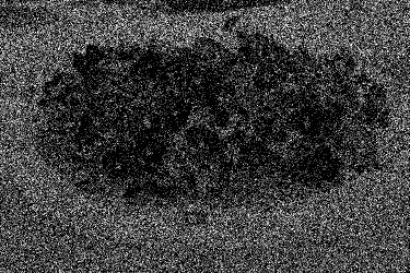 Figure 1
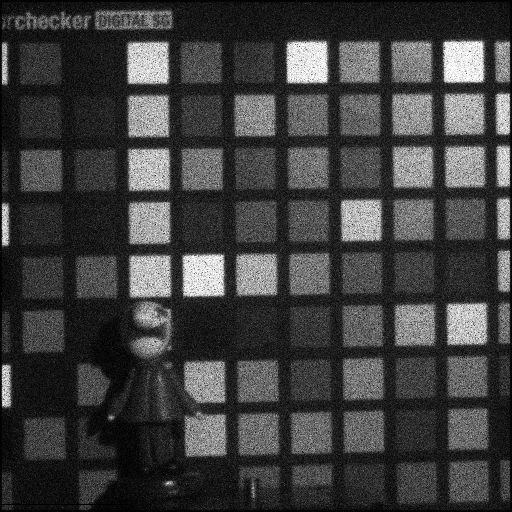 Figure 2
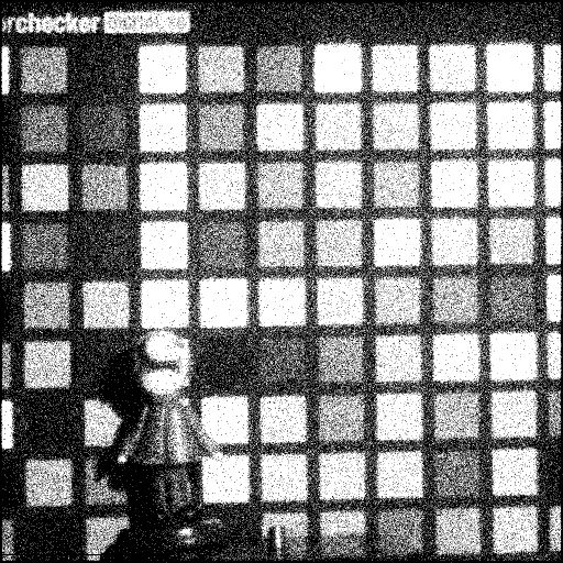 Figure 3
 Figure 4
 Figure 5
 Figure 6
 Figure 7
 Figure 8
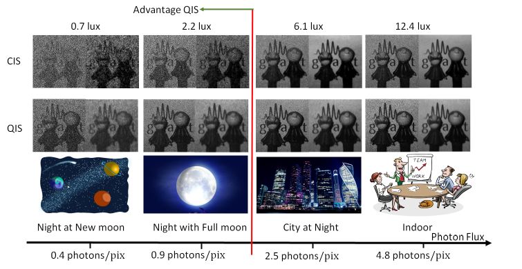 Figure 9
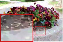 Figure 10
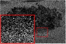 Figure 11
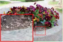 Figure 12
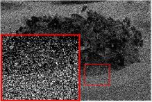 Figure 13
 Figure 14
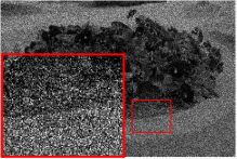 Figure 15
 Figure 16
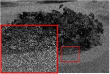 Figure 17
 Figure 18
 Figure 19
 Figure 20
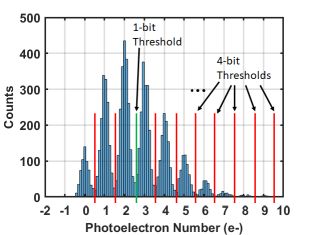 Figure 21
 Figure 22
 Figure 23
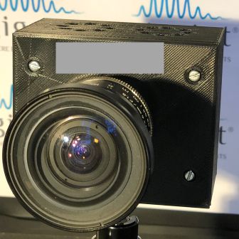 Figure 24
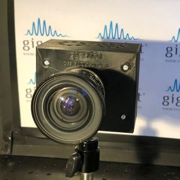 Figure 25
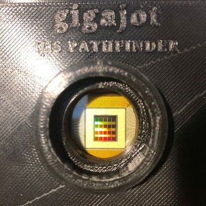 Figure 26
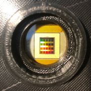 Figure 27
 Figure 28
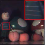 Figure 29
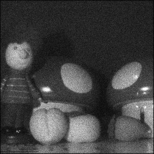 Figure 30
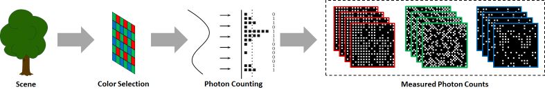 Figure 31
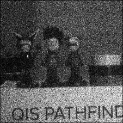 Figure 32
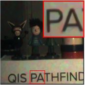 Figure 33
 Figure 34
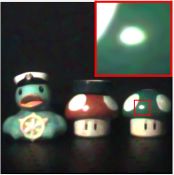 Figure 35
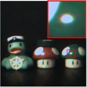 Figure 36
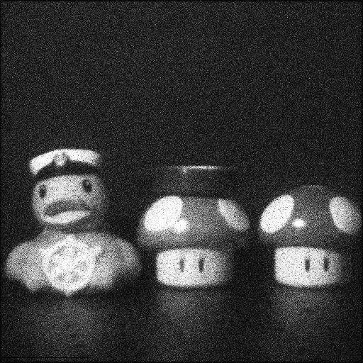 Figure 37
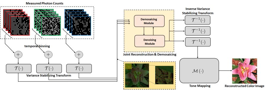 Figure 38
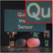 Figure 39
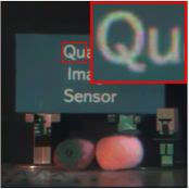 Figure 40
Peer Reviews
No public reviews on file for this paper yet. If you reviewed it on a platform where reviews are public (OpenReview, ICLR, NeurIPS, ICML), you can paste yours below so the community can read it here.
Videos
No videos yet. Explain this paper in a talk, walkthrough, or lecture? Add one.
Megapixel photon-counting color imaging using quanta image sensor
Abhiram Gnanasambandam
\authormark1,* Omar Elgendy
\authormark1 Jiaju Ma
\authormark2 and Stanley H. Chan\authormark1
\authormark1School of Electrical and Computer Engineering, Purdue University, West Lafayette, IN 47907, USA
\authormark2 Gigajot Technology Inc., Pasadena, CA 91107, USA
\authormark* [email protected]
Abstract
Quanta Image Sensor (QIS) is a single-photon detector designed for extremely low light imaging conditions. Majority of the existing QIS prototypes are monochrome based on single-photon avalanche diodes (SPAD). Passive color imaging has not been demonstrated with single-photon detectors due to the intrinsic difficulty of shrinking the pixel size and increasing the spatial resolution while maintaining acceptable intra-pixel cross-talk. In this paper, we present image reconstruction of the first color QIS with a resolution of pixels, supporting both single-bit and multi-bit photon counting capability. Our color image reconstruction is enabled by a customized joint demosaicing-denoising algorithm, leveraging truncated Poisson statistics and variance stabilizing transforms. Experimental results of the new sensor and algorithm demonstrate superior color imaging performance for very low-light conditions with a mean exposure of as low as a few photons per pixel in both real and simulated images.
††journal: oe††articletype: Research Article
\homepage
https://engineering.purdue.edu/ChanGroup/
1 Introduction
Quanta image sensor (QIS) is a concept proposed by E. Fossum in 2005 aiming to overcome the limited sensor performance with the continuously shrinking pixel size [1, 2]. In a CMOS image sensor [3], images are acquired by accumulating hundreds to thousands of photoelectrons in each pixel and converting the charges to voltages and then to digital signals. As pixel size shrinks, the amount of photons that fall on individual pixels drops. Under low-light (or high-speed imaging) conditions, photon shot noise dominates the acquisition process. As the photon becomes scarce, eventually the signal-to-noise ratio will drop to a point that no meaningful images can be generated. Small pixel also reduces the full-well capacity which limits the dynamic range. QIS overcomes the problem by spatial-temporally oversampling the scene. In a QIS, each “image pixel” is partitioned into a group of smaller pixels called jots, and each jot is sensitive enough for photon counting. Over the past decade, numerous studies have demonstrated the feasibility of QIS, with a few prototypes developed [4, 5, 6, 7, 8]. On the image reconstruction side, various methods have also been proposed [9, 10, 11, 12].
Despite the advances in QIS hardware and image reconstruction algorithms, one important open problem is the color imaging capability of QIS. Color imaging in low light is important for many computer vision applications such as night-vision. It is also important in biological studies, where using brighter light may lead to degradation of the biological matter. While active color imaging have been demonstrated using SPAD in [13] passive color imaging using QIS is difficult for two reasons. First, the resolution of a typical single-photon detector array is not high, e.g., pixels [14], or most recently pixels [8]. If a color filter array such as the standard Bayer pattern is implemented, the effective resolution will be halved to or . For detection/tracking applications [15] this might be sufficient; but for photography the resolution could be low compared to the mainstream CMOS image sensors. Second, the color reconstruction of QIS data is different from CMOS image sensors because the QIS data is acquired under sparse-photon conditions with much lower signal-to-noise ratio. The demosaicing algorithm of QIS data needs to overcome the photon shot noise and accurately reproduce the color information. As we will discuss, QIS requires a joint reconstruction and demosaicing on top of the truncated Poisson statistics, a problem that has not been studied.
In this paper, we report the first demonstration of QIS color imaging. The QIS Pathfinder camera module developed at Gigajot Technology (as shown in Fig. 4) was used in this demonstration. The camera sensor has the same core design as the sensor described in [5], but has a Bayer pattern color filter array implemented on-chip. It has a spatial resolution of , single-bit and multi-bit photon-counting outputs, and up to fps speed in single-bit mode. Figure 1 shows a snapshot of the work presented in this paper. The key innovation, besides the sensor, is a new customized image reconstruction algorithm which enables joint reconstruction and demosaicing of raw QIS data. Our method leverages a few recently developed techniques in the QIS literature, including the transform-denoise method [10] and the Plug-and-Play Alternating Direction Method of Multipliers (ADMM) [16]. We demonstrate both our new sensor and the new algorithm on real data, and make quantitative evaluation based on synthetic data.
2 Megapixel quanta image sensor
When the concept of QIS was first proposed, the two mainstream design methodologies to realize single-photon detection were the electron-multiplying charge-coupled device (EMCCD) [6] and the single-photon avalanche diode (SPAD) [17, 18]. Both devices amplify the signal from a single photoelectron with a physical phenomenon called electron avalanche multiplication, where high electrical voltage (typically higher than 20V) is used to accelerate the photoelectron to produce more free electrons through collision. SPAD is more widely adopted in consumer applications because of its excellent low-noise performance and temporal resolution. The SwissSPAD [19, 20, 8] and the SPAD developed at University of Edinburgh [7, 14] are two better known examples. However due to its fabrication technology SPAD often has to make compromise in at least one of the three factors - low dark current, high quantum efficiency, and small pixel pitch. The QIS we use in this paper is based on a new type of single-photon detector proposed by Ma et al. [4, 21, 2, 5, 22]. The approach is to enhance the voltage signal generated by a single photoelectron by reducing the capacitance of the pixel output node so that the single-photon signal can overcome the background thermal noise.
Table 1 shows a comparison between a conventional CMOS image sensor, SPAD, and the prototype QIS used in this work. Among the listed different sensor parameters, the most noticeable difference between the QIS and SPADs is the small pixel pitch, where the QIS realized 1.1 m pixel size, but SPADs typically have a pitch size around 5-20 m. The smaller pixel size makes high spatial resolution (e.g. 10s or 100s of megapixel) possible with a small optical format (e.g. 1/4”). Another advantage of QIS over SPADs is the high quantum efficiency. Quantum efficiency measures the percentage of photons that are detectable by the sensor, which is critical for low-light imaging. SPAD cameras generally have a low quantum efficiency (e.g. 50%), because of low fill-factor and low photon detection capability normally called photon detection efficiency aka PDE. While low fill factor can be alleviated to an extent by using optical solutions such as microlens light-pipe. This reduces the photosensitive areal percentage in the SPAD pixels and limits the quantum efficiency. In contrast, since electron avalanche gain is not required in the QIS device, it has a quantum efficiency over 80% within the visible wavelengths.
Figure 2 shows comparison between real QIS image and a simulted CIS image. We note that we assume that the CIS no dark current. Even without considering the advantages of a lower dark current, the performance of QIS in photon starved regime is much better than the CIS.
3 QIS color imaging model
The imaging model of a color QIS is illustrated in Fig. 3. Relative to the previous QIS imaging models, e.g., [12, 10, 11], the new model considers a color filter array which allows us to select wavelengths and multiple color channels. There are a few essential components in the model.
Spatial oversampling. We represent the discretized scene image as a column vector , where is the number of pixels, , , and are the light intensities of the red, green and blue channels, respectively. QIS was originally designed as a spatial-temporally oversampling device which samples each pixel using jots spatially. This means every pixel has measurements, and totally there are measurements. Thus, the model of this oversampling process is
[TABLE]
where represents the -fold upsampling and interpolation filtering. The constant is a gain factor. In our current prototype, the oversampling factor is as we want to maximize the spatial resolution. In this case, we have , and .
Color filter array. To obtain color information, a color filter is placed on the top of each jot to collect light for only one of the RGB colors, and filter out the remaining two colors. This process is represented by three mutually exclusive diagonal matrices or masks: , and for the red, green and blue channels, respectively. These matrices contain either zeros or ones on the diagonal, and .
Incorporating the color filter array, the light exposure on the jots of QIS is represented by
[TABLE]
We call the mosaiced image. If we let , then and are related by
[TABLE]
Photon arrival. The photon arrival of QIS is modeled as a Poisson process. Let be a non-negative random integer denoting the number of photons arrived at each jot during one integration period. Then, the probability of observing is
[TABLE]
For single-bit QIS, we put a voltage comparator to threshold the arrived photon count into a binary decision. Thus, the read out of each jot is a binary random variable with if and if , where is a threshold.
For multi-bit QIS, we use an -bit quantizer to quantize the measurement. In this case,
[TABLE]
In other words, we count the photons until the number reaches a threshold. When the threshold is reached, we report the maximum number before saturation.
Assumptions. While the above model is theoretically tractable, we made three assumptions. The first is regarding the read noise associated with . If read noise is present, the measured photon count will become where is typically i.i.d. Gaussian. We assume that the read noise is negligible compared to the photon count, and can be eliminated by the thresholding process. We find that this is often the case with the QIS device used in this paper, which provides ultra-low read noise (0.24e- rms at room temperature) and accurate photon-counting capability. See Fig. 5 for an actual measurement of the photon count.
The second assumption we make is that the multi-bit saturation does not happen. That is, during the multi-bit sensing, we will never reach the upper threshold and so , which is a standard Poisson random variable. In terms of hardware, this can be achieved by implementing an automatic exposure control scheme so that the threshold is increased when the scene is too bright. We will leave this to a follow up paper as it is outside the scope of this work.
The third assumption we make is that the camera is fast enough to catch up the scene movement, and the scene remains static during the multiple temporal samplings. This allows us to utilize multiple independent measurements over time to improve the statistics. In this case, the probability distribution of becomes
[TABLE]
where is the Poisson count at pixel in time .
4 QIS color image reconstruction
The task of image reconstruction is to recover color scene from the measurements . In the gray-scale setting, we can formulate the problem as maximum-likelihood and solve it using convex optimization tools [25, 12, 9, 11]. We can also use learning-based methods, e.g., [26, 27, 28, 29] to reconstruct the signal. The method we present here is based on the transform-denoise approach by Chan et al. [10]. We prefer transform-denoise because it is a physics-based approach and is robust to different sensor configurations. For example, in learning-based approaches, if we change the number of frames to sum, we need to train a different model or neural network.
4.1 Reconstruction pipeline
The pipeline of the proposed reconstruction algorithm is shown in Fig. 6. Given the random variable with realizations , we first sum the frames to generate a single image :
[TABLE]
In the future, this step can be integrated into the hardware of the camera, so that the output of the camera will be the sum of multiple frames. Depending on whether we are using the single-bit mode or the multi-bit mode, the statistics of follows either a Binomial distribution or a Poisson distribution. In single-bit mode, the distribution of is
[TABLE]
where is the probability of obtaining a zero in the binary variable . As shown in [11] is the incomplete Gamma function. In multi-bit mode, since a sum of Poisson remains a Poisson, the distribution of is
[TABLE]
If we assume that there is no processing of the bits besides temporal summation, then a simple maximum-likelihood of the probability will return us the solution:
[TABLE]
The operation can be interpreted as a tone-mapping.
4.2 Variance stabilizing transform
Now, we want to process the data besides just summing the frames. However, in either single-bit or multi-bit mode, the Binomial or the Poisson statistics are not easy as the variance changes with the mean. This prohibits the use any off-the-shelf algorithms that are based on i.i.d. Gaussian assumptions, e.g., denoising or inpainting.
The variance stabilizing transform (VST) is a statistical technique that tries to alleviate the changing variance problem [30, 31, 32]. Among the different types of VSTs, we are particularly interested in the two transforms originally proposed by F. Anscombe in 1948 [33]:
[TABLE]
Here, the first transform is called the Anscombe Binomial, and the second is called the Anscombe Poisson. Both transforms are pixel-wise, meaning that we can apply the transform to each pixel independently. As proved in [10] and [33], the variance of is 1/4 for both the single-bit and the multi-bit case. The inverse is simply the algebraic inverse (or the unbiased inverse if we follow [34]).
The important question for color imaging is now that the photon count is the result of applying a color filter array matrix . That is, instead of observing the full color , we only observe a subsampled version . However, since is point-wise and is a concatenation of three non-overlapping binary matrices, it holds that
[TABLE]
Consequently, if we define as the observed measurement (which is available from the sensor) and treat as the unknown quantity to be determined, then the problem can be formulated as
[TABLE]
where is some regularization function controlling the smoothness of . Note that (12) is a standard demosaicing-denoising problem assuming i.i.d. Gaussian noise.
4.3 Joint reconstruction and demosaicing
The optimization problem in (12) is a standard least squares with regularization function . Thus, most convex optimization algorithm can be used as long as is convex. In this paper, we adopt a variation of the alternating direction method of multiplier (ADMM) by replacing with an off-the-shelf image denoiser. Such algorithm is coined the name Plug-and-Play (PnP) [35] (and different versions thereafter [16]).
For the particular problem in (12), the PnP ADMM algorithm iteratively updates the following two steps:
Demosaicing Module:
[TABLE]
Denoising Module:
[TABLE]
and updates the Lagrange multiplier by . Readers interested in the detailed derivation can consult, e.g., [16]. Here, is an internal parameter that controls the convergence. The operator is an off-the-shelf image denoiser, e.g., Block-matching and 3D filtering (BM3D) or deep neural network denoisers. The subscript denotes the denoising strength, i.e., the hypothesized “noise variance”. Since is a diagonal matrix, the inversion is pointwise.
4.4 Non-iterative algorithm
The m pixel pitch of the proposed QIS can potentially lead to a spatial resolution as high as or even higher than a conventional CMOS sensor. When this happens, in certain applications we can trade-off the color reconstruction efficiency and the resolution. For example, instead of using one jot for one pixel, we can use four jots for one pixel as shown in Fig. 7.
Using four jots for one pixel allows us to bypass the iterative ADMM steps because there is no more missing pixel problem. In this case, the matrix will become , and hence (12) is simplified to a denoising problem with different noise levels for the three channels. In particular, the green channel has half of the variance of the red and the blue. For implementation, we can modify a denoiser, e.g., BM3D to accommodate the different noise variances. Since there is no more ADMM iteration, the algorithm is significantly faster. While we have used BM3D to demonstrate the results, any off the shelf denoiser which is used in CIS based cameras can be used to denoise the image for the four-jot to one-pixel method. We would also like to stress on the fact that both the Anscombe transform and the transform can be implemented as a look up table. So, this method can be as fast a current denoiser being used in a CIS based camera.
4.5 Comparisons
We compare the proposed method with several existing methods on a synthetic dataset shown in Fig. 8. We simulate the raw color QIS data by assuming a Bayer pattern and using the image formation pipeline described in the previous section. We demosaic the images using: (a) a baseline method using MATLAB’s demosaic preceded by gray-scale BM3D denoising of , , and channels and followed by color BM3D denoising; (b) Least-squares luma-chroma demultiplexing (LSLCD) method [36], which has a built-in BM3D denoiser; (c) Hirakawa’s PSDD method [37, 38], which does joint denoising and demosaicing for Poisson noise; and (d) the proposed method using BM3D with . We apply variance stabilizing transform, except for PSDD which is designed for Poisson noise. The results show that the proposed method has a significantly better performance, both in terms of Peak Signal to Noise Ratio (PSNR) and visual quality.
5 Experimental results
5.1 Synthesized QIS data
We conduct a synthetic experiment to provide a quantitative evaluation of the performance of the proposed algorithm. To this end, we simulate the image formation pipeline by passing through color images to generate the QIS raw input data, with different number of bits. Figure 9 shows one example, and in the Supplementary Report we have additional examples.
In our simulation, we assume that the number of QIS frames is , and the average number of photon per pixel is , , and photons / frame for 1-bit, 2-bit, 3-bit and 4-bit QIS, respectively. On the measurement side, we generate single-bit and multi-bit data by thresholding the raw sensor output. To reconstruct the image, we use the proposed method with PnP and BM3D. The parameters are set as and and for 1-bit, 2-bit, 3-bit and 4-bit QIS, respectively. With as low as 1-bit, the reconstructed image in Fig. 9 is already capturing most of the features. As the number of bits increases, the visual quality improves.
5.2 Real QIS data
We first show the reconstruction of an image of the Digital SG chart. We generate two sets of measurements: (a) a set of 50 one-bit frames, quantized with a threshold , and (b) a set of 10 five-bit frames. We use PnP and BM3D with and for the 1-bit and 5-bit data, respectively. After reconstruction, the results are multiplied by a color correction matrix to mitigate any color cross-talk. This matrix is generated by linear least square regression of the 24 Macbeth color patches that lies inside the SG ColorChecker chart. The results in Fig. 1 suggest that while 1-bit mode has color discrepancy with the ground truth, the 5-bit mode is producing a reasonably-high color accuracy.
Next, we show the result of imaging real scenes. See Fig. 10. In this experiment, the exposure time for each frame is set to 50s. The average number of photons per pixel is approximately 4.2 photons for the ”QIS” sign image, 3 photons for the Pathfinder image, 1.9 photons for the duck image, and 2.9 photons for the mushroom image. For all images, we collect the data using a 5-bit QIS.
We demonstrate two algorithms: (i) the proposed transform-denoise framework using PnP + BM3D, and (ii) assuming four-jots to one-pixel scenario by trading half of the spatial resolution. The typical runtime on an unoptimized MATLAB code is approximately 4 minutes for PnP, and 10 seconds for the four-jot to one-pixel method. An interesting observation is that even in the lower-resolution case, the details are not significantly deteriorated unless we zoom-in. However, the speed up we get is substantial.
6 Conclusion and discussion
We demonstrated the first color imaging for a mega-pixel Quanta Image Sensor (QIS). We designed a joint reconstruction-demosaicing algorithm for the quantized Poisson (and Poisson) statistics of the sensor data. Our solution involves a variance stabilizing transform and an iterative (and a non-iterative) algorithm. By integrating the sensor and the new algorithm, the sensor is able to acquire color images at a photon level as low as a few photons per pixel, a level that would be difficult for standard CMOS image sensors.
7 Acknowledgement
The authors thank Prof. Eric Fossum for many valuable feedback. The 1Mjot color Quanta Image Sensor used in the demonstration was designed by J. Ma, S. Masoodian, and D. Starkey at Dartmouth College Advanced Image Sensor Laboratory led by Dr. Eric Fossum. The sensor was manufactured by Taiwan Semiconductor Manufacturing Company (TSMC). The camera module developed at Gigajot Technology was partially supported by National Science Foundation SBIR program. A Gnanasambandam, O. Elgendy and S. H. Chan are supported, in part, by the U.S. National Science Foundation under Grant CCF-1718007.
The reference list from the paper itself. Each links out to its DOI / PubMed record.
- 1[1] E. R. Fossum, “Some Thoughts on Future Digital Still Cameras,” in Image Sensors and Signal Processing for Digital Still Cameras, (CRC, 2006), 305–314.
- 2[2] E. R. Fossum, “Gigapixel digital film sensor (DFS) proposal,” in Nanospace Manipulation of Photons and Electrons for Nanovision Systems, The 7th Takayanagi Kenjiro Memorial Symposium and the 2nd International Symposium on Nanovision Science, Hamamatsu, Japan, (2005).
- 3[3] E. R. Fossum, “Active pixel sensors: Are CC Ds dinosaurs?” in Charge-Coupled Devices and Solid State Optical Sensors III, vol. 1900 (International Society for Optics and Photonics, 1993), 2–15.
- 4[4] J. Ma and E. R. Fossum, “A pump-gate jot device with high conversion gain for a quanta image sensor,” \Journal Title IEEE Journal of the Electron Devices Society 3 (2015).
- 5[5] J. Ma, S. Masoodian, D. A. Starkey, and E. R. Fossum, “Photon-number-resolving megapixel image sensor at room temperature without avalanche gain,” \Journal Title Optica 4 (2017).
- 6[6] J. Hynecek, “Impactron-a new solid state image intensifier,” \Journal Title IEEE Trans. Electron Devices 48 (2001).
- 7[7] N. A. W. Dutton, L. Parmesan, A. J. Holmes, L. A. Grant, and R. K. Henderson, “320x 240 oversampled digital single photon counting image sensor,” in Proceedings of IEEE 2014 Symposium on VLSI Circuits Digest of Technical Papers, (IEEE, 2014).
- 8[8] C. Bruschini, S. Burri, S. Lindner, A. C. Ulku, C. Zhang, I. M. Antolovic, M. Wolf, and E. Charbon, “Monolithic SPAD arrays for high-performance, time-resolved single-photon imaging,” in Proceedings of International Conference on Optical MEMS and Nanophotonics, (IEEE, 2018).