A Spring Propelled Extreme Environment Robot for Off-World Cave Exploration
Steven Morad, Thomas Dailey, Leonard Vance, Jekan Thangavelautham

TL;DR
This paper introduces SPEER, a low-cost spring-propelled microbot system designed for exploring off-world caves and pits, overcoming access limitations of traditional rovers with disposable, lightweight spherical microbots.
Contribution
The paper presents a novel, cost-effective microbot design and launch system for off-world cave exploration, enabling access to previously unreachable geological formations.
Findings
Feasibility demonstrated through simulation of lunar pit exploration.
Microbots can be built for under $500 using commercial components.
The system allows for lightweight, disposable exploration microbots with onboard sensors.
Abstract
Pits on the Moon and Mars are intriguing geological formations that have yet to be explored. These geological formations can provide protection from harsh diurnal temperature variations, ionizing radiation, and meteorite impacts. Some have proposed that these underground formations are well-suited as human outposts. Some theorize that the Martian pits may harbor remnants of past life. Unfortunately, these geo-logical formations have been off-limits to conventional wheeled rovers and lander systems due to their collapsed ceiling or 'skylight' entrances. In this paper, a new low-cost method to explore these pits is presented using the Spring Propelled Extreme Environment Robot (SPEER). The SPEER consists of a launch system that flings disposable spherical microbots through skylights into the pits. The microbots are low-cost and composed of aluminium Al-6061 disposable spheres with an…
Click any figure to enlarge with its caption.
 Figure 1
 Figure 2
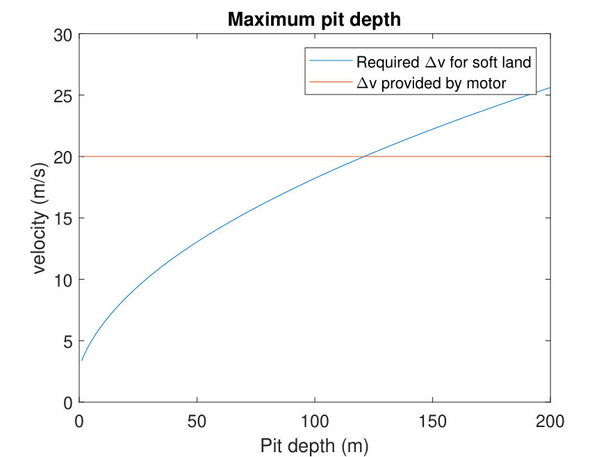 Figure 3
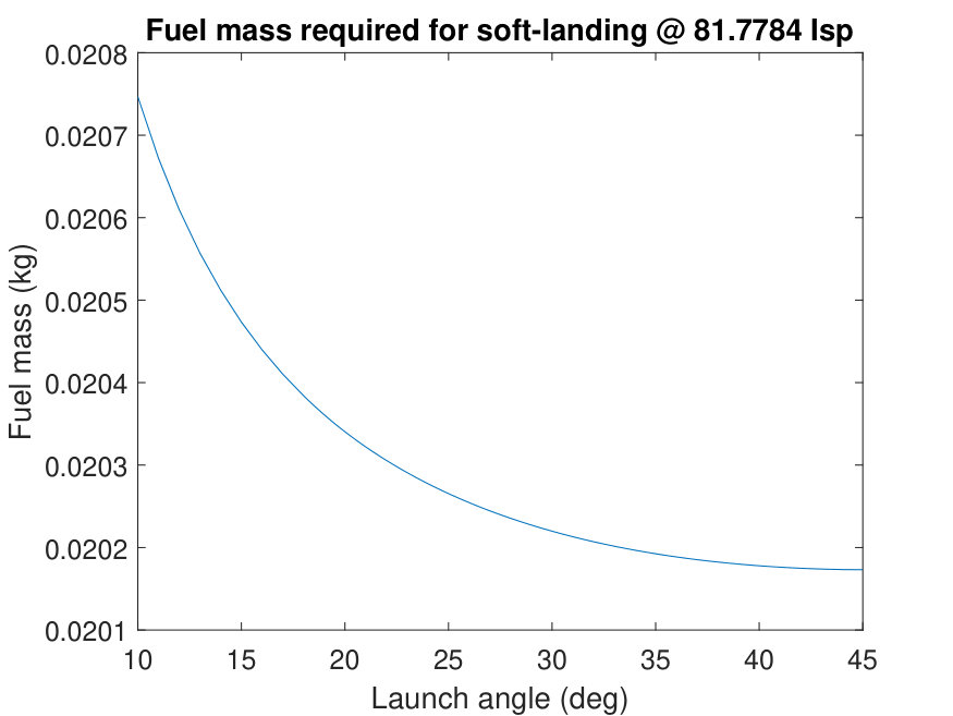 Figure 4
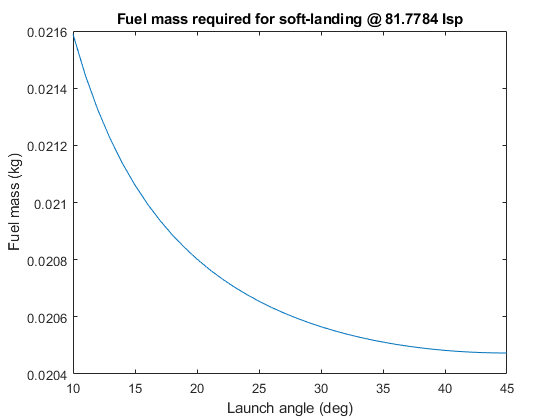 Figure 5
 Figure 6
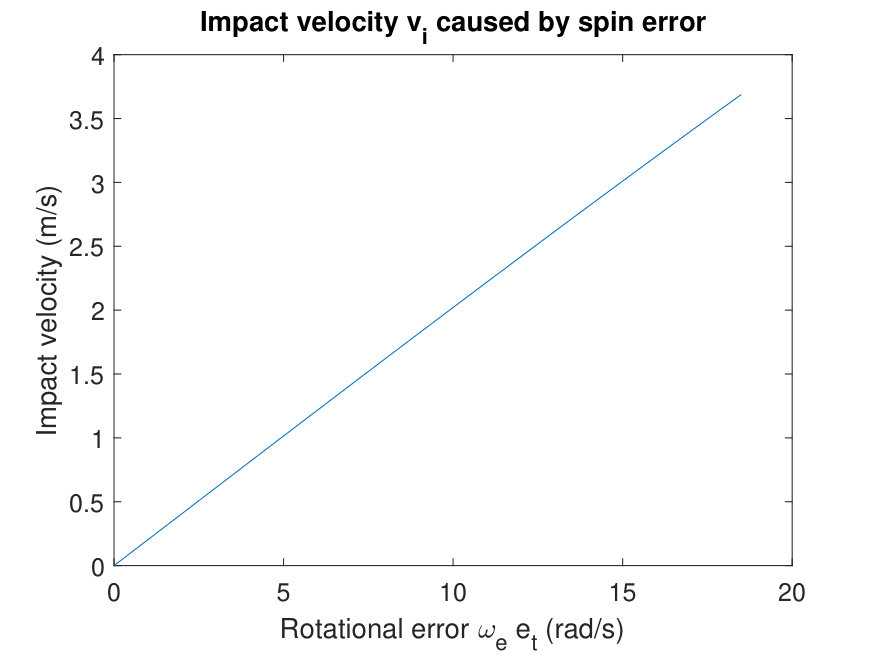 Figure 7
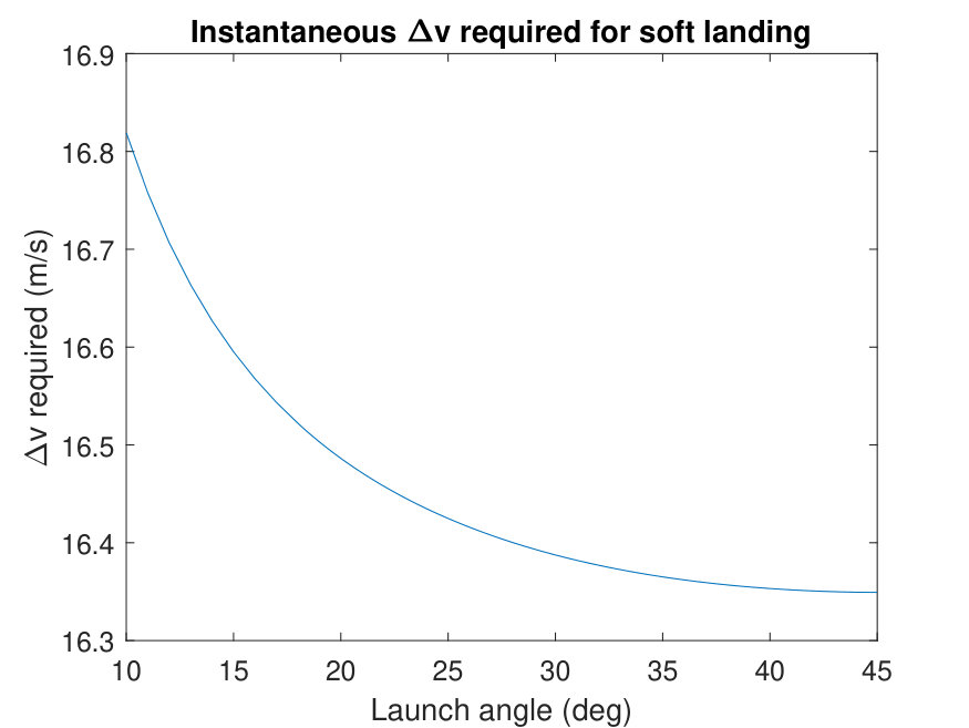 Figure 8
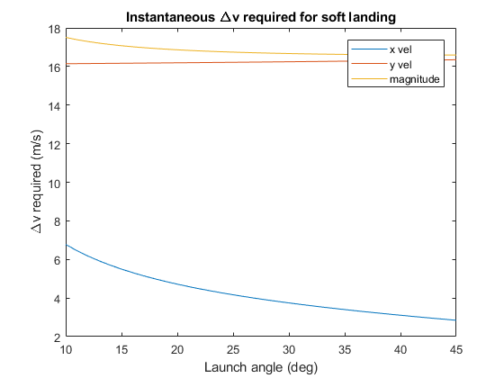 Figure 9
 Figure 10
 Figure 11
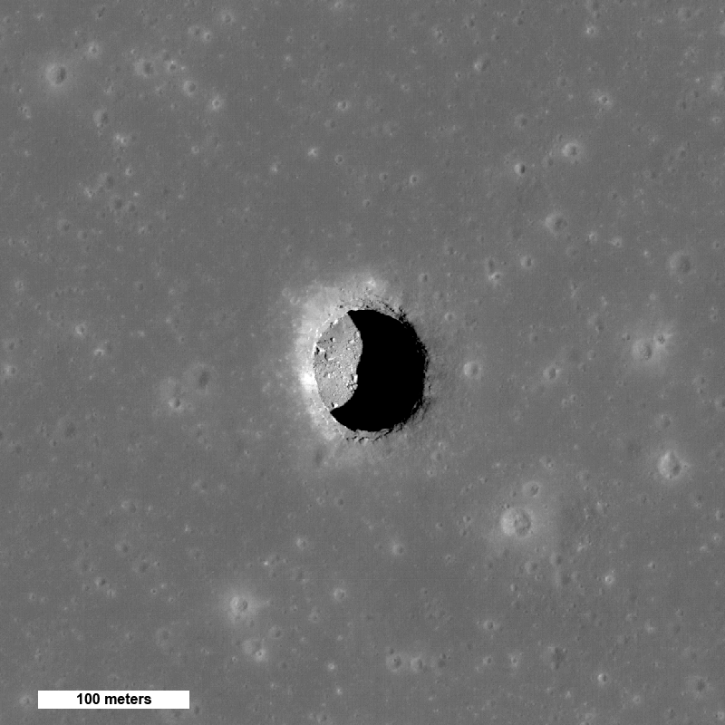 Figure 12
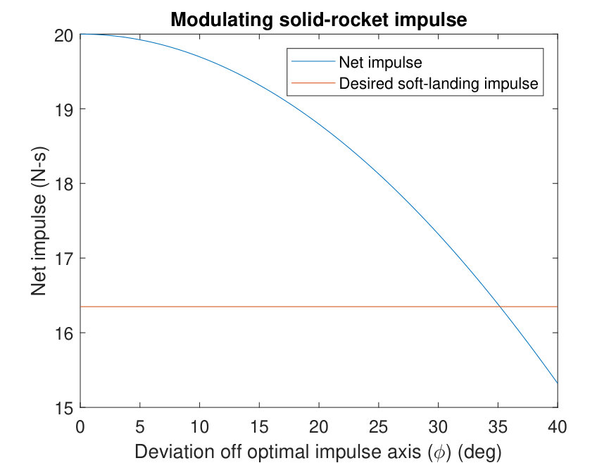 Figure 13
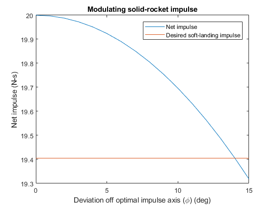 Figure 14
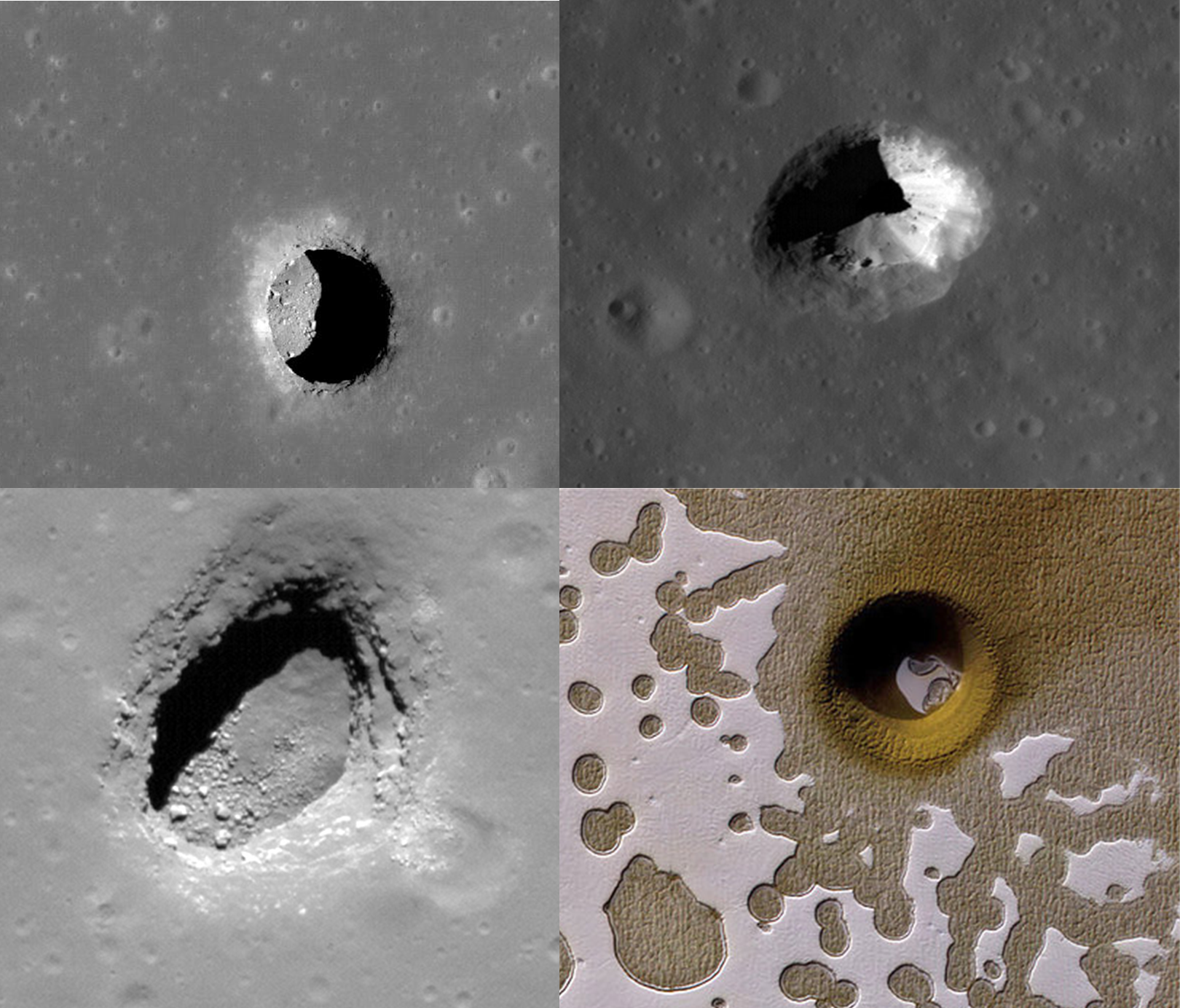 Figure 15
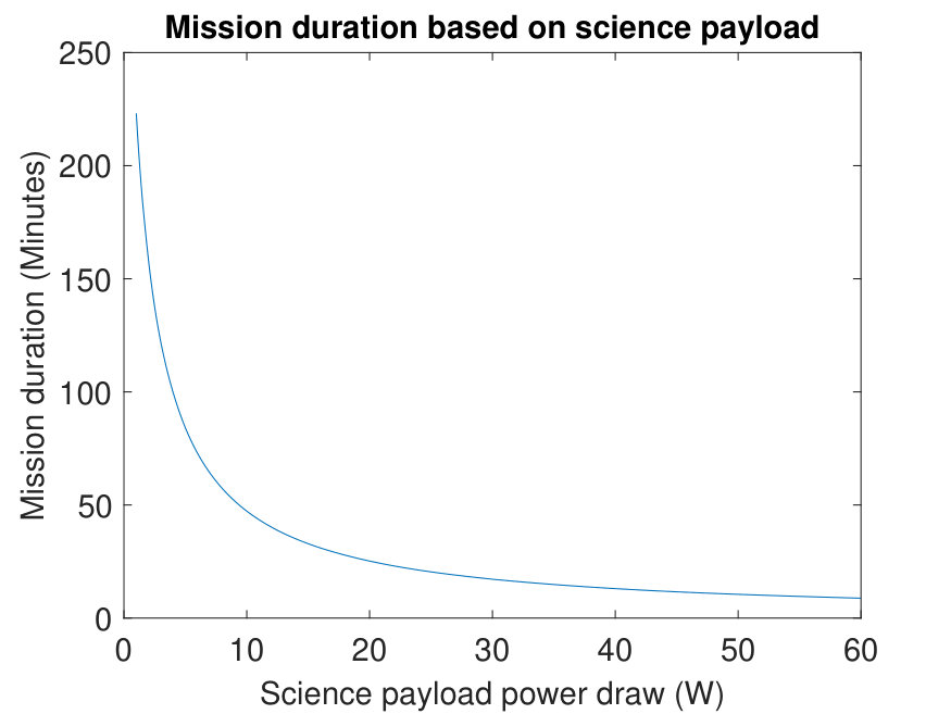 Figure 16
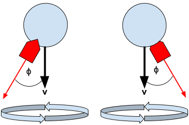 Figure 17
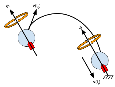 Figure 18
 Figure 19
 Figure 20
 Figure 21
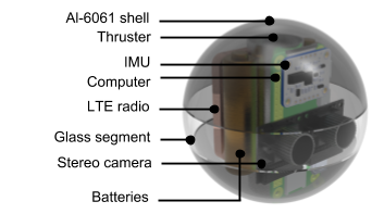 Figure 22
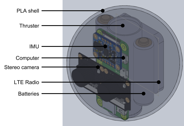 Figure 23
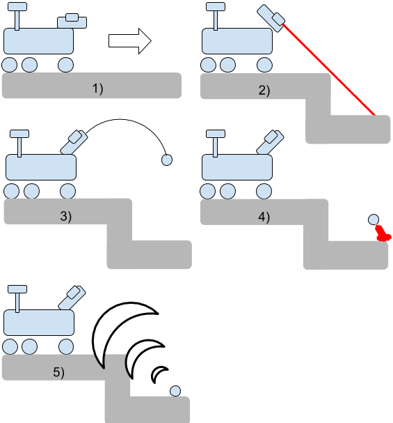 Figure 24
 Figure 25
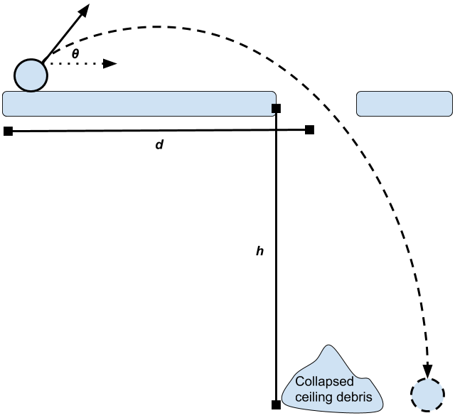 Figure 26
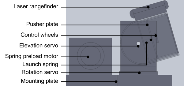 Figure 27
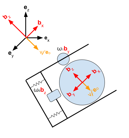 Figure 28
 Figure 29
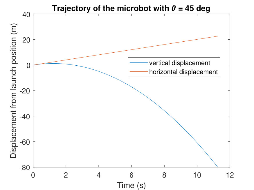 Figure 30
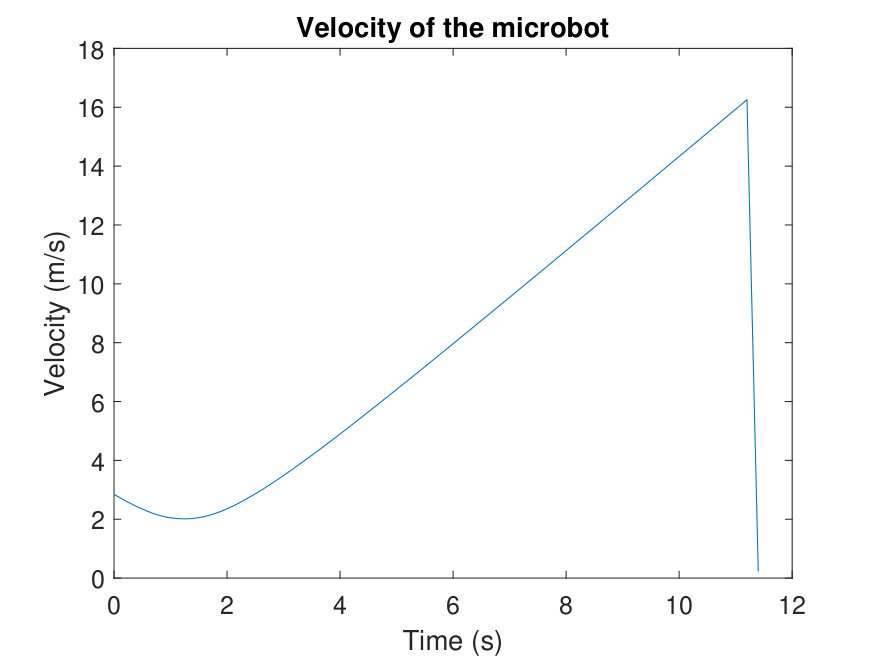 Figure 31
| Symbol | Meaning |
|---|---|
| Matrix | |
| Vector | |
| Lunar acceleration (1.625 m/s2) | |
| Bot mass (1 kg) | |
| Force | |
| Impulse | |
| Net impulse | |
| Launch spring displacement | |
| Time | |
| Time at launch | |
| Time to move | |
| Time of terrain impact | |
| Launch speed | |
| Speed just before impact | |
| Impact speed | |
| Launch angle | |
| Inertial frame | |
| Body-fixed bot frame | |
| Horizontal distance to pit opening | |
| Pit depth | |
| Rotation matrix from to | |
| Rotation matrix from to | |
| Optimal impulse vector | |
| Tangent vector to | |
| Desired impulse vector | |
| Angle between and | |
| Error in | |
| Angular speed of wheel 0 | |
| Angular speed of wheel 1 | |
| Angular speed for spin stabilization | |
| Angular speed for impulse modulation | |
| Net angular speed | |
| Error angular speed | |
| Actual angular speed | |
| Unit vector for | |
| Unit vector for | |
| Unit vector for | |
| Impulse duration of thruster |
| Component | Mass (g) |
|---|---|
| 2mm thick Al-6061 shell | 102 |
| 2mm thick borosilicate glass | 19 |
| Estes D12-3 20N-s solid rocket engine | 42 |
| 2Energizer L91VP 4.5 Wh lithium battery | 29 |
| Raspberry-pi zero computer | 9 |
| 2Pi camera module | 6 |
| Adafruit 6-axis IMU | 3 |
| Sixfab 4G LTE radio | 18 |
| Wiring | 3 |
| Systems subtotal | 231 |
| Science payload | 769 |
| Total | 1000 |
| Component | Mass (g) |
|---|---|
| cm aluminum pusher plate | 17 |
| Steel frame for pusher plate | 20 |
| PC105 4012 N/m spring | 5 |
| STP-MTRH stepper motor | 3800 |
| Pololu 1501MG high torque servo | 120 |
| Parallax 120RPM continuous servo | 84 |
| 1m of 0.25 inch steel cable | 160 |
| JSumo 13.25mm radius silicone wheel | 26 |
| Margin for mounting plates and brackets | 300 |
| Raspberry-pi zero computer | 9 |
| Lightware SF11 laser rangefinder | 35 |
| Pi camera module | 6 |
| Total | 4592 |
| Component | Energy (mWh) |
|---|---|
| 2LV91VP Lithium battery | 9000 |
| Raspberry-pi zero computer | 120 |
| 2Pi camera module | 200 |
| Sixfab 4G LTE Radio | 1100 |
| Science Payload | variable |
Peer Reviews
No public reviews on file for this paper yet. If you reviewed it on a platform where reviews are public (OpenReview, ICLR, NeurIPS, ICML), you can paste yours below so the community can read it here.
Videos
No videos yet. Explain this paper in a talk, walkthrough, or lecture? Add one.
ieee-aero-2018
steven_morad
Steven D. Morad
Space and Terrestrial Robotic Exploration
(SpaceTREx) Laboratory
Dept. of Aerospace and Mechanical Eng.
University of Arizona
Thomas Dailey
Space and Terrestrial Robotic Exploration
(SpaceTREx) Laboratory
Dept. of Aerospace and Mechanical Eng.
University of Arizona
Leonard Dean Vance
Space and Terrestrial Robotic Exploration
(SpaceTREx) Laboratory
Dept. of Aerospace and Mechanical Eng.
University of Arizona
Jekan Thangavelautham
Space and Terrestrial Robotic Exploration
(SpaceTREx) Laboratory
Dept. of Aerospace and Mechanical Eng.
University of Arizona
(September 2018)
A Spring Propelled Extreme Environment Robot for Off-World Cave Exploration
steven_morad
Steven D. Morad
Space and Terrestrial Robotic Exploration
(SpaceTREx) Laboratory
Dept. of Aerospace and Mechanical Eng.
University of Arizona
Thomas Dailey
Space and Terrestrial Robotic Exploration
(SpaceTREx) Laboratory
Dept. of Aerospace and Mechanical Eng.
University of Arizona
Leonard Dean Vance
Space and Terrestrial Robotic Exploration
(SpaceTREx) Laboratory
Dept. of Aerospace and Mechanical Eng.
University of Arizona
Jekan Thangavelautham
Space and Terrestrial Robotic Exploration
(SpaceTREx) Laboratory
Dept. of Aerospace and Mechanical Eng.
University of Arizona
(September 2018)
Abstract
Pits on the Moon and Mars are intriguing geological formations that have yet to be explored. These geological formations can provide protection from harsh diurnal temperature variations, ionizing radiation, and meteorite impacts. Some have proposed that these underground formations are well-suited as human outposts. Some theorize that the Martian pits may harbor remnants of past life. Unfortunately, these geological formations have been off-limits to conventional wheeled rovers and lander systems due to their collapsed ceiling or ”skylight” entrances. In this paper, a new low-cost method to explore these pits is presented using the Spring Propelled Extreme Environment Robot (SPEER). The SPEER consists of a launch system that flings disposable spherical microbots through skylights into the pits. The microbots are low-cost and composed of aluminium Al-6061 disposable spheres with an array of adapted COTS sensors and a solid rocket motor for soft landing. By moving most control authority to the launcher, the microbots become very simple, lightweight, and low-cost. We present a preliminary design of the microbots that can be built today using commercial components for under 500 USD. The microbots have a total mass of 1 kg, with more than 750 g available for a science instrument. In this paper, we present the design, dynamics and control, and operation of these microbots. This is followed by initial feasibility studies of the SPEER system by simulating exploration of a known Lunar pit in Mare Tranquillitatis.
Contents
1 Introduction
Pits on the Moon and Mars are geological mysteries that could provide valuable insight into past geo-history and shelter future humans (Fig. 1). Daga et al. discusses the reasoning for the exploration of these pits in a planetary science decadal survey report [1]. These pits are one of the most promising locations for future research outputs, because they shield inhabitants from solar radiation, micrometeorites, and temperature variations of hundreds of degrees [2], [3]. On the Moon and Mars, some of these pits are believed to remnants of lava tubes. On the Moon, some of these pits are in polar permanently shadowed regions and may contain water-ice. On Mars, they offer protection from UV light, provide nearly constant temperatures, and potentially nutrient-rich volcanic regolith. This makes lava tubes one of the likely candidates for past life on Mars [4]. These pits are relatively untouched by surface processes and are time capsules that can tell us about the early formation of the solar system.
Robots have not been sent inside an off-world pit, due to the difficulty and risk of vertically descending into a dark, unknown environment. To better understand if these pits harbor past-life or water, satellite observation is not sufficient [1]. Missions are required that provide in-situ measurements.
Entering these pits consists of surviving a vertical drop on the order of one hundred meters [6]. The floor near the opening is covered with rubble, causing mobility challenges. The ceiling entrances may not be structurally sound, and may collapse as a heavy rover drives up to the edge. Most pit exploration platforms fall into one of two categories: a tethered rappelling robot such as AXEL [7], or microbots [8], including the SphereX platform [9] [10] [11] [12].
Whittaker discusses both microbot and tethered robot approaches in his Nasa Innovative Advanced Concepts (NIAC) proposal on the robotic exploration of these pits [13]. Tethered robots allow for a power and communications relay to be situated at the edge of the skylight, while a robot descends into the pit. JPL is currently pursuing this avenue with the AXEL and MoonDiver projects [7]. There are concerns that the tether may cause issues. Upon ascent a tethered robot could get lodged under a rock, causing a mission failure. That being said, tethers are a versatile approach that allow for extended time in the pits because of their ability to transfer solar energy from the surface. Many recent robotic platforms for Lunar pit exploration have started to converge towards the tethered design.
Microbots offset the risks of one expensive rappelling robot by allowing multiple microbots to fail, without sacrificing the mission [8]. Microbots would make their way to the opening of the pit, jump into the pit, and softly land using thrusters. Whittaker’s concern with microbots is that they require extremely small components, that are decades away and may never actually exist. Designs like the SphereX microbot [9] [10] [11] [12] require fast reaction wheels and multiple microthrusters to land inside the pit. While these components now exists thanks to wide availability of CubeSat components, they are still more expensive than initially envisioned. For these reasons, we set out to design a simple and low-cost microbot for Lunar and Martian pit exploration. Our intention is to have platforms of various costs to be tailored to specific missions.
2 Design
We propose the Spring Propelled Extreme Environment Robot (SPEER) system to develop a truly low-cost and disposable microbot. The SPEER system is a package consisting of a spring powered launcher and multiple microbot projectiles. The launcher uses a jack-in-the-box spring system to deploy one microbot at a time. Control happens before the bot leaves the launcher. A ballistic trajectory is computed and the bot is spin-stabilized by two wheels in the launcher before launch.
The microbot projectile is a AL-6061 (aluminium) sphere, 4 cm in radius with a solid-rocket motor, IMU, batteries, camera, and LTE radio (Fig. 2, Table 2). Other options were considered for propulsion including use of water-electrolysis propulsion [14] and water steam propulsion [15]. Both provide additional advantages including increased control authority, however the water waste product makes it inappropriate for science mission where the focus is to find water ice in the pits.
The electronics are rated to survive the estimated -20 oC environment of a Lunar pit [16]. Note that there is no reaction control system, which drastically cuts down on the mass of each microbot. The bot has room for science instruments, but other than that, it is a very simple system. By shifting all control to the launcher, large mass margins are afforded for science instruments and secondary payloads inside the bot.
A rover would drive a safe distance from the edge of a pit and launch a SPEER bot. As the bot flies into the cave, it collects valuable terrain data by fusing its stereo camera and IMU measurements. The bot then uses its solid-thruster to safely land. Stereo imagery and video is streamed in real-time to the rover, in case landing fails. This ensures even if the bot is destroyed on impact, valuable imagery of the pit is broadcasted on time. After landing, the microbot can unpack and utilize the onboard science instrument and transmit findings back to Earth via the rover (Fig. 5).
2.1 Spin Stabilization
The Lunar pits are on the order of one hundred meters deep, so a free-falling bot will impact at around 18 m/s. This is too fast to survive, so a powered descent is required. The bot will need to orient its thruster to soft-land. In spacecraft orientation this is usually done using a control moment gyro or with three separate reaction wheels. CubeSat-grade gyros and reaction wheels are heavy, slow and expensive.
Reaction wheels and gyros were not always available. Explorer-1 was the first satellite launched by the United States back in the 1950’s but reaction wheels were not in use until the 1960’s [17]. Explorer-1 utilized a method known as spin stabilization to orient itself. Spin stabilization is where a satellite spins along an axis to keep it pointed in a certain direction. The gyroscopic effect keeps the craft pointed toward its target, even with disturbances. We use spin stabilization to keep the SPEER oriented correctly.
The SPEER launcher has a camera and laser rangefinder to find a landing site for the bot. Given the range and elevation of the landing site, we can compute the bot trajectory before launch (Eq. 5). We find , the velocity vector at the moment before impact (Eq. 11). A spin imparted along right before launch ensures the thruster stays pointed in the correct direction for a soft landing (Fig. 6, Eq. 16). This removes the need for any reaction control system in the microbot itself.
2.2 Soft Landing with a Solid-Fuel Engine
Efficient soft landing is difficult. Electric CubeSat thrusters do not provide enough force to counteract gravity on the Moon or Mars. Liquid-fuelled CubeSat engines have a mass of over one kilogram, partially due to the heavy pressurized fuel container and flow control system. Some liquid-fuel engines also require additional power to heat or cool the propellant before use. Solid-fuel engines used in model rockets do not have these requirements and are therefore very simple and light. They consist of a propellant and oxidizer packaged in a tube that is ignited by running current through a resistor.
The issue with using a solid-fuel engine is that they have a set impulse that cannot be changed. The engine cannot be easily shutdown and we do not know exactly how much v the SPEER bot will need before inspecting the cave. This would normally make solid-fuel engines unsuitable for soft-landing application, but in our case the thruster can be modulated by adding a torque-free precession to the bot using the launcher. The launcher uses powered wheels to create a precession by imparting a secondary angular velocity , orthogonal to . This allows us to reduce the net impulse by pointing the thruster away from (Fig. 7, Eq. 21).
3 Ballistics Analysis
We derive the equations of motion for the bot. Since the majority of the bot’s flight is unpowered, it’s motion is mostly ballistic with a soft-landing impulse . The trajectory of the bot is illustrated in Fig. 8.
The bot leaves the launcher at time with launch velocity at angle . The compression of the launch spring is computed as a function of using the following well established equation:
[TABLE]
The entire trajectory is in one plane so we can use planar dynamics. The acting forces are just gravity and an impulsive thrust.
[TABLE]
[TABLE]
Integrating we find
[TABLE]
[TABLE]
The impulse is instantaneous at , so it can be ignored for most trajectory calculations. We compute the required launch velocity from the time to move ,
[TABLE]
[TABLE]
[TABLE]
[TABLE]
We can compute the velocity right before the instantaneous impulse,
[TABLE]
[TABLE]
Plugging into Eq. 4
[TABLE]
[TABLE]
4 Rotational Analysis
Now that the ballistics equations are derived, we analyze the rotation required for a soft landing. We must ensure the thruster is pointed correctly, resulting in the impulse cancelling out the velocity such that . The mass of the bot is distributed in such a way that the center of mass is in the center of the sphere. The thrust vector will always point through the center of mass, which means the thrust will not apply a moment or affect the rotation.
We define the negative of our optimal impulse vector in the inertial frame as
[TABLE]
and attach a body-fixed frame to the bot such that the thruster points along the axis. Two wheels, are used to orient the bot and apply angular velocities to the bot.
4.1 Applying Spin Stabilization
We want the bot to be robust against noise that would point the thruster () away from , so we spin stabilize about . We use to align with
[TABLE]
Now that is aligned with We can spin wheel 0 at to impart an angular velocity of to the bot. Let be the radius of the wheel and be the radius of the bot. Assuming no-slip between the wheel and bot, we have
[TABLE]
Using Eq. 16, we show how to apply a spin stabilization of to keep the thruster pointing towards (Fig. 10).
4.2 Applying a Precession
Because of the nature of solid-fuel thrusters, we want to be able to modulate our net impulse by creating a torque-free precession of angle about (Fig. 7). is our desired impulse while is the impulse rating of the thruster.
[TABLE]
[TABLE]
With , we construct rotation matrix . We can use this to compute our desired impulse magnitude and desired impulse vector
[TABLE]
[TABLE]
After wheel 0 has spin stabilized the bot, wheel 1 rotates at along to create a precession to modulate the thruster impulse.
[TABLE]
Eq. 21 tells us how fast to spin wheel 1 to apply a precession.
4.3 Nulling the Horizontal Components
To ensure that the horizontal components of the velocity are nulled, we need to make sure that the thruster completes full rotations over the impulse duration. One can imagine a case where the entire impulse happens over one quarter of a rotation, which would produce a nonzero impulse in the plane. We will find an expression for the magnitude , such that the impulse happens over a multiple of .
To complete full rotations over a given impulse duration we have
[TABLE]
So the angular velocity magnitude is constrained by the impulse duration
[TABLE]
A thruster that burns over one second would require of .
4.4 The Effect of Noise on Impact Velocity
We generally want to pick the largest we can. This reduces the divergence between the desired thruster direction and the noise present in the actual thruster direction , ultimately reducing the impact velocity. We analyze how spin stabilization reduces the impact velocity , to make for a softer landing. Let the actual spin be a sum of the desired spin and some error .
[TABLE]
We can express the vectors geometrically with the resulting rotation vector deviating from by angle (Fig. 9).
We can find using the definition of the dot product
[TABLE]
Thus, we can see how the optimal thruster direction changes to with noise .
We show exactly how this noise effects impact velocity . Let , , and be the unit vectors for the respective ’s, with being the instantaneous thruster impulse. Then we have
[TABLE]
We want zero landing velocity so
[TABLE]
We find the impact magnitude as
[TABLE]
[TABLE]
[TABLE]
4.5 Putting it all Together
With spin stabilization component and impulse modulation component , we can find an equation for the total angular velocity of the bot (Fig. 10).
[TABLE]
5 Discussion
One possible application of the SPEER robots is to probe lunar pits to determine if ice resides in them. As the temperature in the pits remains stable at around -20 oC, the conditions could be ideal for ice accumulation. To determine if there is ice in these pits, each SPEER would need to carry a science payload such as a compact neutron generator and detector. The other possibility is to just a carry a neutron generator and have the neutron detector on the rover. This would require line-of-sight between the rover and SPEER.
5.1 Science Payload
Large pieces of ice can be identified using the cameras, but that is not the case for smaller ice crystals dispersed in the regolith. NASA’s curiosity rover carried an experiment called Dynamic Albedo of Neutrons (DAN). This experiment used a 14 MeV neutron generator to detect water and hydrated minerals up to 1m below the surface. Sandia National Labs recently designed a compact neutron generator, called the ”neutristor”. The neutristor was designed to be placed near tumors to allow cancer patients to continue their radiation therapy at home. As such, the neutristor was built to be powered by a single battery, with a compact 1.5 3cm form factor [18].
Like the DAN experiment, the neutristor also has an output energy of 14 MeV. Due to its low power usage and small size, it can easily fit inside a SPEER bot. In addition, the SPEER bot would ideally carry the neutron detector. Like the bots, the neutristor is disposable, with an operational time of 1000 seconds. Multiple bots can be launched to different places in the pit to find the areas with the highest concentration of ice or hydrated minerals.
5.2 Dynamics
Using the equations presented in the analysis, we can compute flight parameters for the pit discovered by Haruyama et al. Haruyama estimates the depth of the pit in the Mare Tranquillitatis as 80m [19]. We want to throw the bot in from distance so that the rover doesn’t drive up to the unstable opening. We assume the bot is launched m from the cave opening, and that the depth of the cave is m (Fig. 8). Optimizing for maximum depth, the bot can soft-land after drops as large as 123.5m. For deeper pits, 14g of the science payload mass can be allocated for the larger 30 N-s thruster variant (Fig. 11(a)).
We look at various launch angles . Since is small, the difference in final velocities is also small (Fig. 12(a)). This translates to a small change in the fuel required (Fig. 12(b)).
In a typical scenario, we select a launch angle of and compute the trajectory of the bot using Eq. 5, plotted in Fig. 13. This results in a desired launch velocity m/s. Using spring stiffness N/m, we use Eq. 1 to compress the spring cm to obtain our launch velocity.
6 Conclusion
We have proposed the SPEER system, which is made entirely of commercial components. The SPEER microbot costs under 500 USD each, with a total mass of 1 kg including up to 770 g of science payload. The components selected are capable of surviving the modest temperatures and low-radiation conditions of a Lunar or Martian pit. We have simulated a deployment of the SPEER architecture for exploration of a Lunar pit in the Marius hills and have provided numerical solutions for a soft touchdown. We have made some simplifying assumptions, but the values show that this is a feasible approach to off-world pit exploration.
SPEER better addresses the problem of microbot designs relying on small components that do not yet exist or are expensive. Certain components, like reaction wheels and liquid-fuel thrusters face reliability challenges due to miniaturization. We remove the need for the reaction wheels by externally spin stabilizing the bots. We add a second spin for impulse control, removing the need for a liquid-fuel thruster. This transfer of control authority from the microbot to the launcher allows for significant mass savings.
In-situ measurements provide a better picture of the inside of these pits than is possible with state-of-the-art recon satellites such as the Lunar Reconnaissance Orbiter (LRO). Lunar and Martian pits provide protection from radiation and diurnal temperature variations. On the Moon, they may contain water ice. On Mars, they may hold remnants of past life. Until we send robots inside them, we will not know. The SPEER system is a cost-effective, low-risk pathway for us to get a first look inside these off-world pits.
7 Future Work
The details of how the SPEER bots are packaged on the rover is not discussed. Some ideas are to place three of them to be packaged in an internally modified 3U PPOD, which would act like a magazine on a firearm.
We are working on building a SPEER prototype. We plan to experimentally test the performance of SPEER in the rugged environments of Arizona and New Mexico. If testing goes well, we plan to look into operating a SPEER system in a practical capacity on Earth. Mapping abandoned mine shafts too small for quadcopters or squeezing through tight crevasses to find trapped mountain climbers are just two Earth-based applications of the SPEER.
The reference list from the paper itself. Each links out to its DOI / PubMed record.
- 1[1] Andrew W Daga et al. “Lunar and martian lava tube exploration as part of an overall scientific survey” In Annual Meeting of the Lunar Exploration Analysis Group 1515 , 2009, pp. 15
- 2[2] J.-P. Williams, D.A. Paige, B.T. Greenhagen and E. Sefton-Nash “The global surface temperatures of the Moon as measured by the Diviner Lunar Radiometer Experiment” In Icarus 283 , 2017, pp. 300–325
- 3[3] Cassandra R Coombs and BRAY Hawke “A search for intact lava tubes on the Moon: Possible lunar base habitats”, 1992
- 4[4] Richard J Léveillé and Saugata Datta “Lava tubes and basaltic caves as astrobiological targets on Earth and Mars: a review” In Planetary and Space Science 58.4 Elsevier, 2010, pp. 592–598
- 5[5] “New Views of Lunar Pits” In NASA Photojournal NASA, 2010
- 6[6] GE Cushing, TN Titus, JJ Wynne and PR Christensen “THEMIS observes possible cave skylights on Mars” In Geophysical Research Letters 34.17 Wiley Online Library, 2007
- 7[7] L Kerber et al. “Moon Diver: A Discovery Mission Concept for Understanding the History of the Mare Basalts Through the Exploration of a Lunar Mare Pit” In New Views of the Moon 2-Asia 2070 , 2018
- 8[8] S. Dubowsky et al. “A Concept Mission: Microbots for Large‐Scale Planetary Surface and Subsurface Exploration” In AIP Conference Proceedings 746.1 , 2005, pp. 1449–1458