Fabric Soft Poly-Limbs for Physical Assistance of Daily Living Tasks
Pham H. Nguyen, Imran I. B. Mohd, Curtis Sparks, Francisco L., Arellano, Wenlong Zhang, Panagiotis Polygerinos

TL;DR
This paper introduces a soft, fabric-based wearable robotic limb that provides physical assistance for daily tasks, featuring systematic design rules, validated performance, and practical demonstrations of manipulation and load-carrying capabilities.
Contribution
The work presents a novel fabric soft poly-limb with systematic design guidelines, validated performance, and practical integration for wearable assistance.
Findings
Can safely carry loads 10.1 times its body weight
Demonstrates effective manipulation and load-carrying in experiments
Design rules enable highly compliant soft robotic limbs
Abstract
This paper presents the design and development of a highly articulated, continuum, wearable, fabric-based Soft Poly-Limb (fSPL). This fabric soft arm acts as an additional limb that provides the wearer with mobile manipulation assistance through the use of soft actuators made with high-strength inflatable fabrics. In this work, a set of systematic design rules is presented for the creation of highly compliant soft robotic limbs through an understanding of the fabric based components behavior as a function of input pressure. These design rules are generated by investigating a range of parameters through computational finite-element method (FEM) models focusing on the fSPL's articulation capabilities and payload capacity in 3D space. The theoretical motion and payload outputs of the fSPL and its components are experimentally validated as well as additional evaluations verify its…
Click any figure to enlarge with its caption.
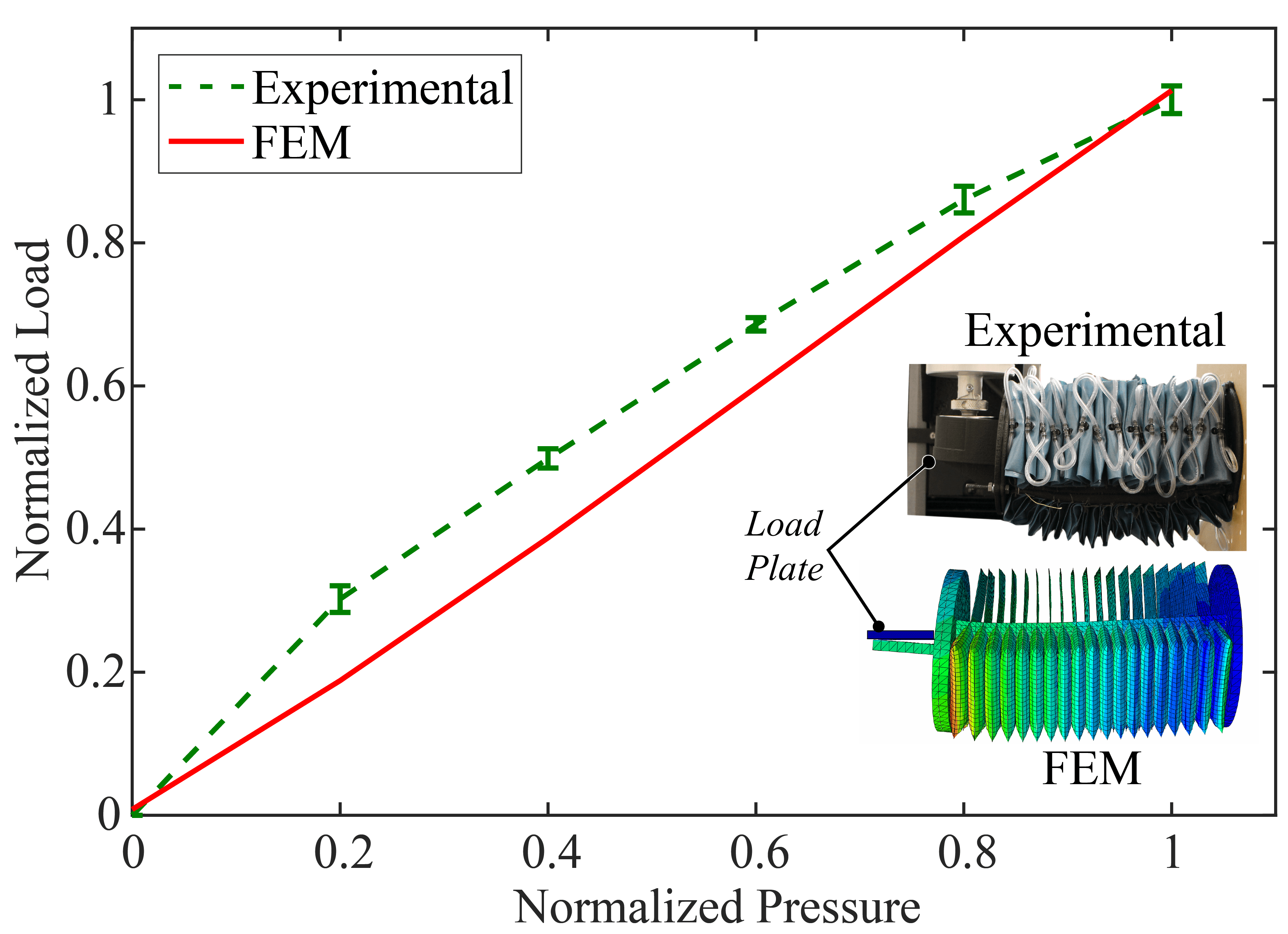 Figure 1
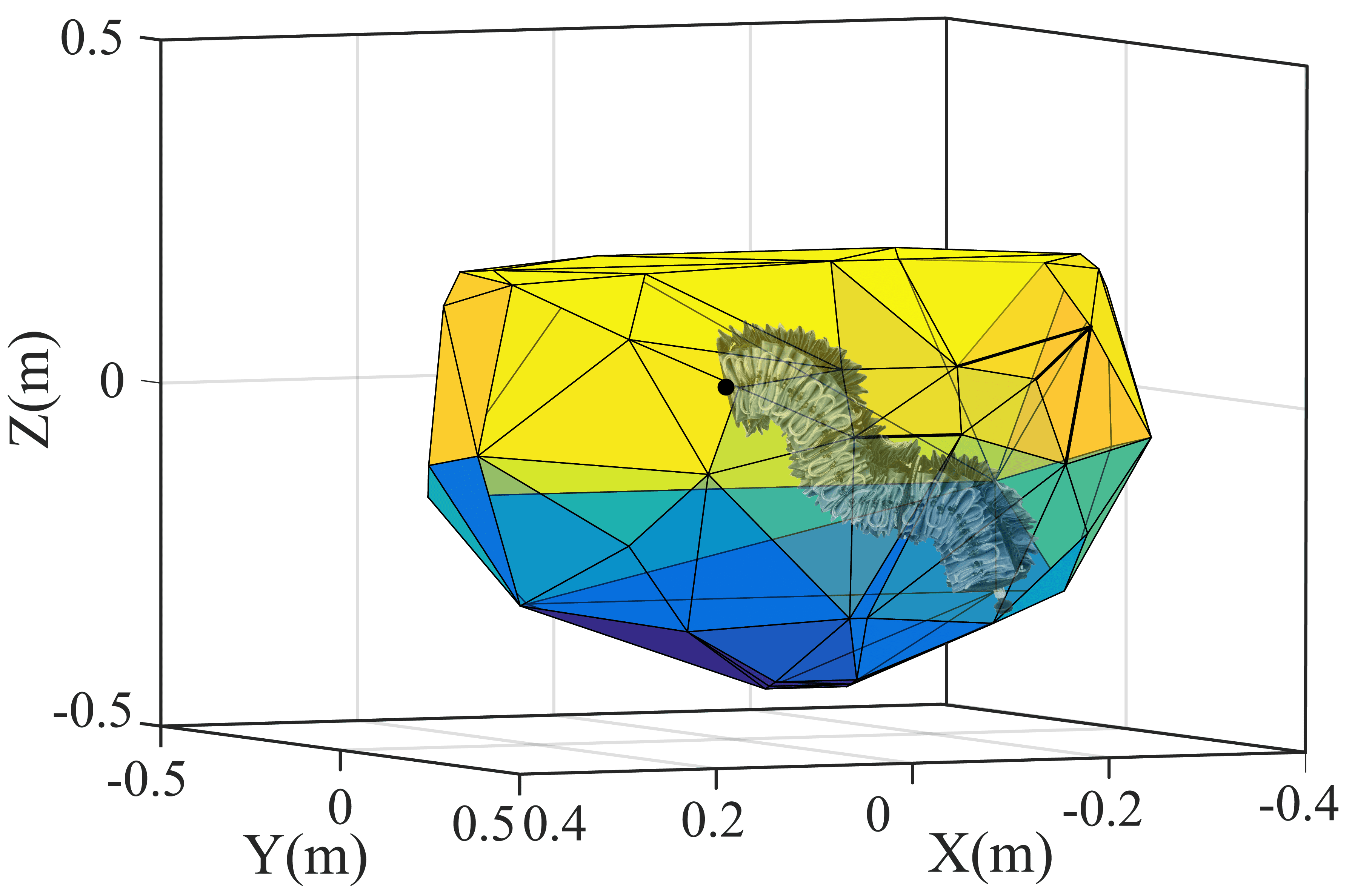 Figure 2
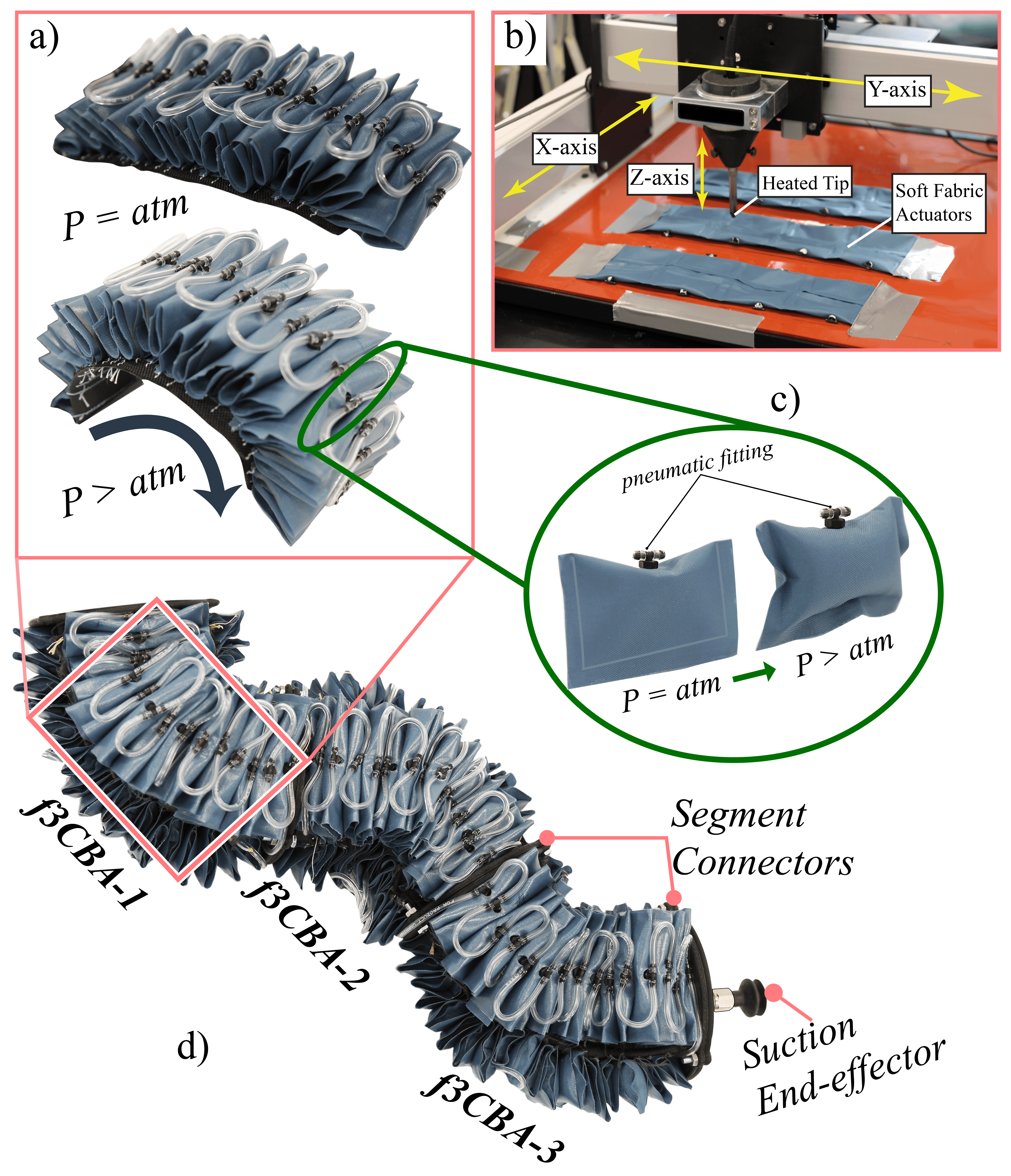 Figure 3
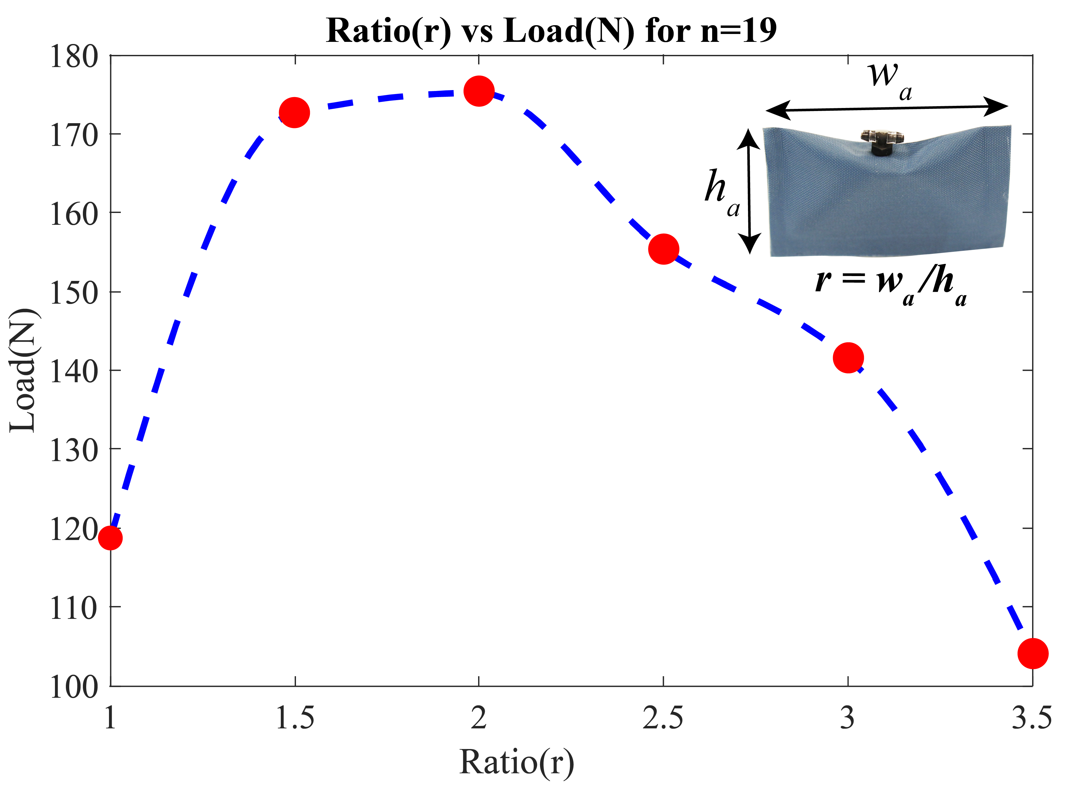 Figure 4
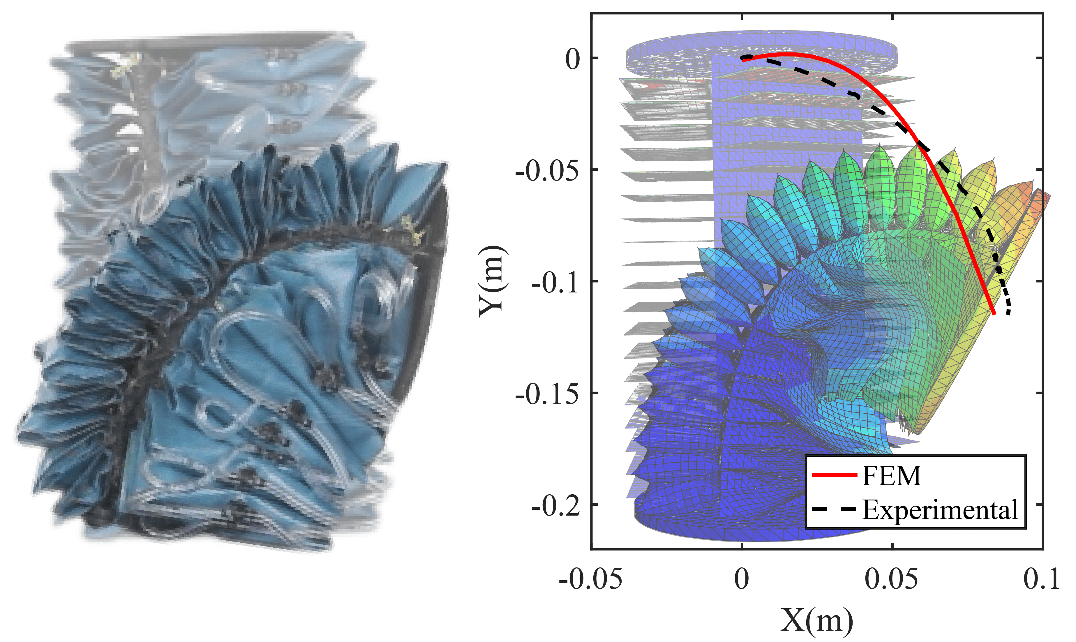 Figure 5
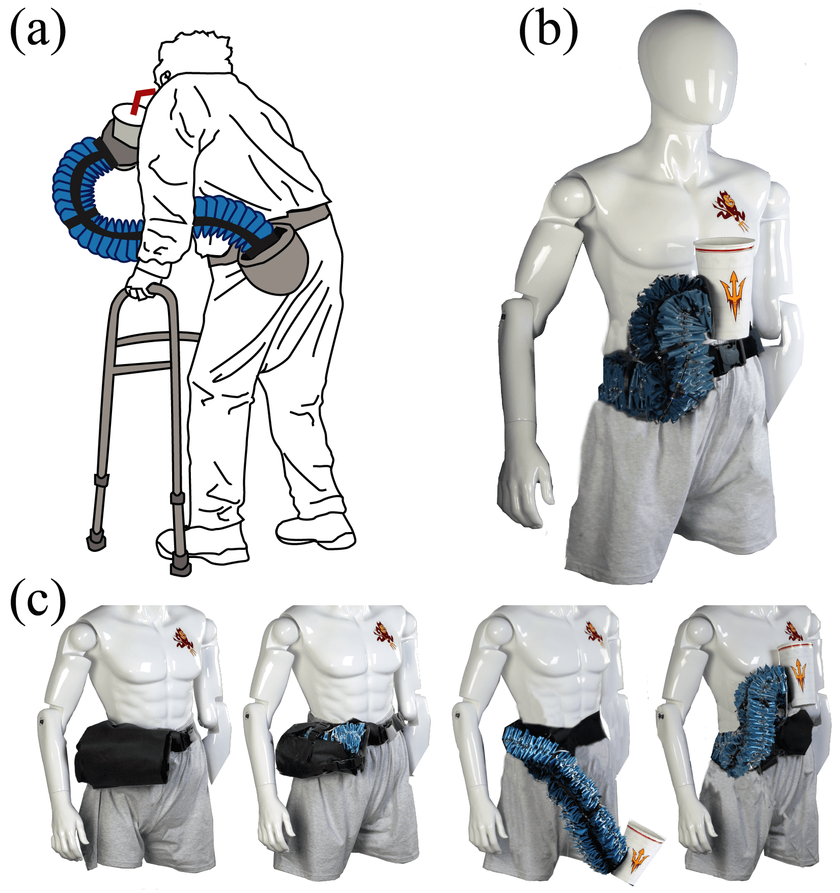 Figure 1
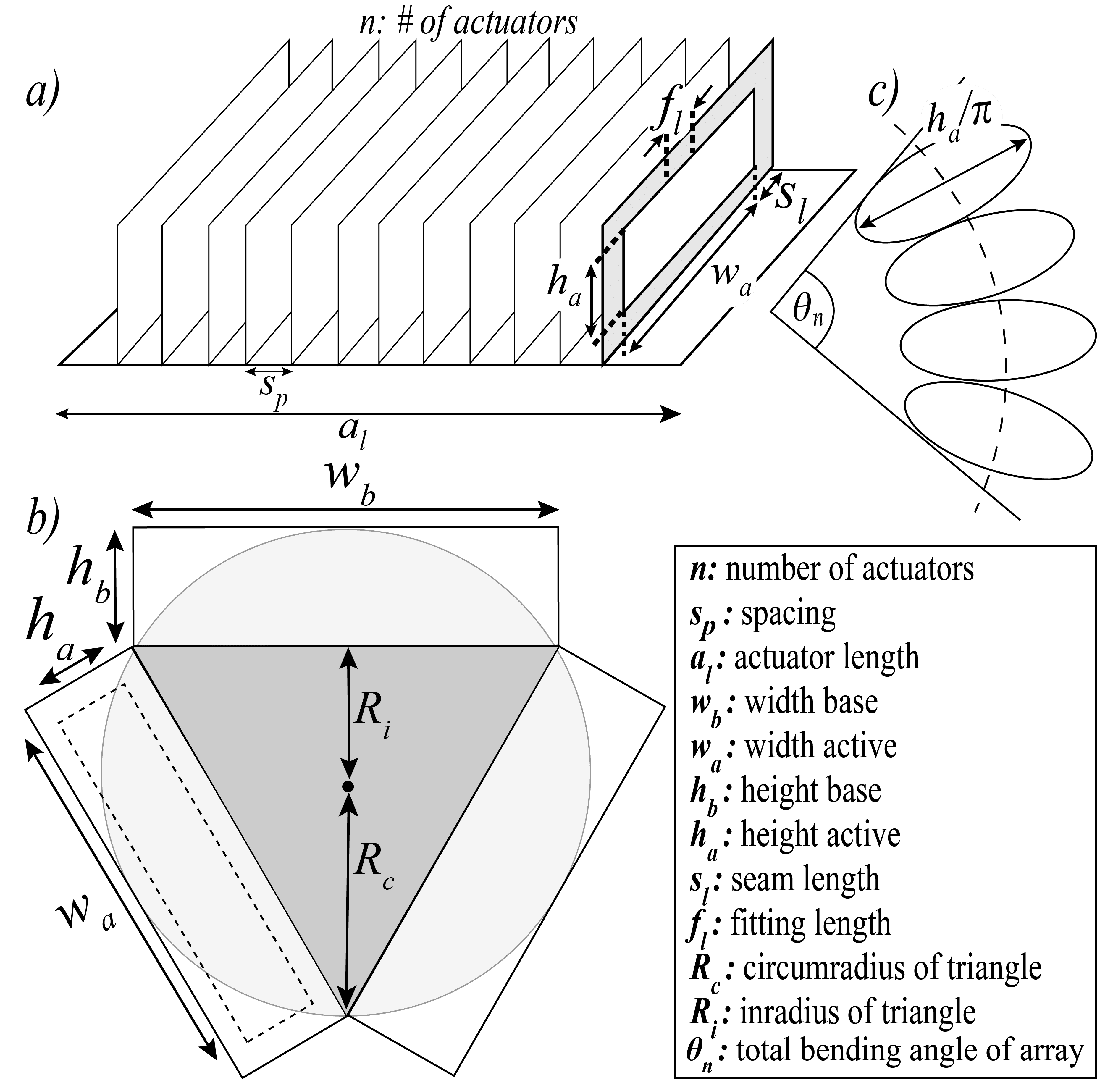 Figure 7
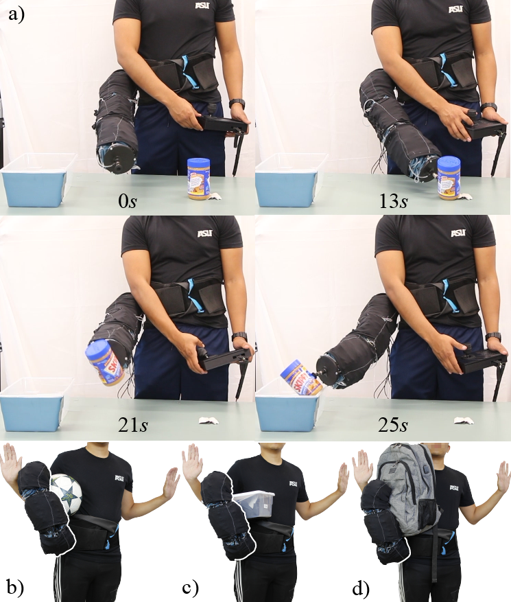 Figure 8
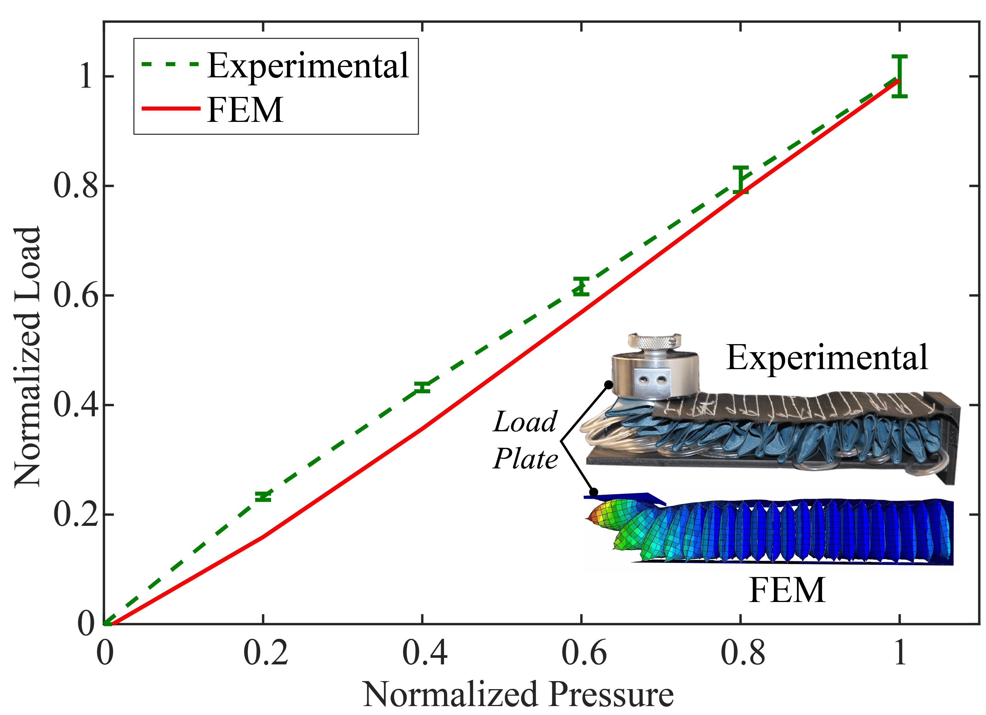 Figure 9
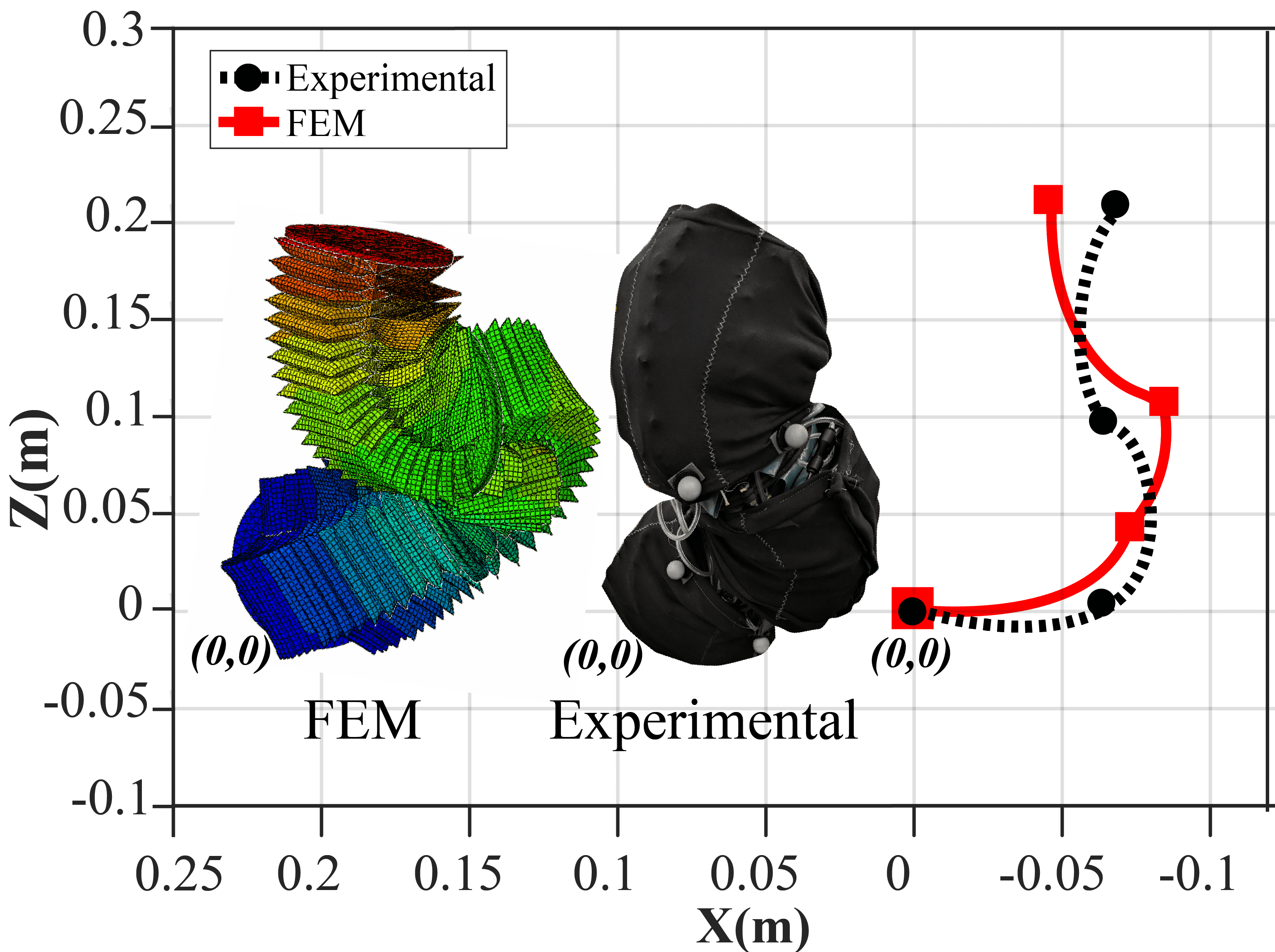 Figure 10
| Characteristics | Requirements |
|---|---|
| Weight of Device | Approx. 1.0 |
| Profile of fSPL | Less than 100 diameter |
| Payload (fully extended) | Approx. 1 |
| Payload (whole-body grasp) | 2x the weight of device |
| Max. Reach Length | Length of male arm (0.59) |
| Min. Retraction Length | Half of fully stretched SPL |
| Safety | Easy to don-and-doff |
| Does not interfere with | |
| biological limb’s movement | |
| Degrees-of-Freedom (DOF) | Infinite DOF (continuum) |
| Degrees of Curvature of Each Segment | 180∘ |
| Material | Density | Seal Strength | Burst |
|---|---|---|---|
| (kg/m3) | (N) | Strength | |
| (MPa) | |||
| Rockywoods 200D | 840.00 | 168.35 | 0.530.04 |
| Outdoor Oxford 200D | 757.58 | 183.68 | 0.480.03 |
| Ripstop 200D | 758.62 | 192.19 | 0.400.017 |
| Seatle Diamond 200D | 892.86 | 164.75 | 0.360.026 |
| DIY Packraft 400D | 982.46 | 155.32 | 0.200.026 |
| DIY Packraft 1000D | 1000.00 | 236.17 | 0.110.02 |
| Taffeta 70D | 700.00 | 150.59 | 0.0480.008 |
| Component | UTM Payload | Free-space Loading | |
|---|---|---|---|
| (N) | Payload (N or kg) | ||
| Exp. | FEM | ||
| Actuator Array | 174.736.37 | 177.2 | – |
| f3BA | 53.731.04 | 56.9 | 58.8 or 6.0 |
| fSPL | 14.910.93 | 20.0 | 14.7 or 1.5 |
| Users | Attempt | Attempt | Attempt | Attempt | Attempt |
|---|---|---|---|---|---|
| 1 | 2 | 3 | 4 | 5 | |
| 1 | 53.28 | 37.28 | 27.17 | 25.16 | 24.70 |
| 2 | 45.34 | 33.88 | 22.33 | 21.43 | 20.79 |
| 3 | 27.68 | 21.89 | 19.60 | 17.00 | 13.12 |
Peer Reviews
No public reviews on file for this paper yet. If you reviewed it on a platform where reviews are public (OpenReview, ICLR, NeurIPS, ICML), you can paste yours below so the community can read it here.
Videos
No videos yet. Explain this paper in a talk, walkthrough, or lecture? Add one.
Fabric Soft Poly-Limbs for Physical Assistance of Daily Living Tasks
Pham H. Nguyen, Student Member, IEEE, Imran I. B. Mohd, Curtis Sparks, Francisco L. Arellano,
Wenlong Zhang*∗*, Member, IEEE and Panagiotis Polygerinos, Member, IEEE Address all correspondence to this author.Pham H. Nguyen, Curtis Sparks, Wenlong Zhang and Panagiotis Polygerinos are with the Polytechnic School, Ira A. Fulton Schools of Engineering, Arizona State University, Mesa, AZ 85212, USA. [email protected]; [email protected]; [email protected] I. B. Mohd The School for Engineering of Matter, Transport and Energy, Ira A. Fulton Schools of Engineering, Arizona State University, Tempe, AZ 85281, USA. [email protected] L. Arellano The School of Biological Health Systems Engineering, Ira A. Fulton Schools of Engineering, Arizona State University, Tempe, AZ 85281, USA. [email protected]
Abstract
This paper presents the design and development of a highly articulated, continuum, wearable, fabric-based Soft Poly-Limb (fSPL). This fabric soft arm acts as an additional limb that provides the wearer with mobile manipulation assistance through the use of soft actuators made with high-strength inflatable fabrics. In this work, a set of systematic design rules is presented for the creation of highly compliant soft robotic limbs through an understanding of the fabric based component’s behavior as a function of input pressure. These design rules are generated by investigating a range of parameters through computational finite-element method (FEM) models focusing on the fSPL’s articulation capabilities and payload capacity in 3D space. The theoretical motion and payload outputs of the fSPL and its components are experimentally validated as well as additional evaluations verify its capability to safely carry loads 10.1x its body weight, by wrapping around the object. Finally, we demonstrate how the fully collapsible fSPL can comfortably be stored in a soft-waist belt and interact with the wearer through spatial mobility and preliminary pick-and-place control experiments.
I INTRODUCTION
Individuals with upper-limb impairments typically experience difficulty performing motor tasks, such as activities of daily living (ADLs). These populations could benefit from a soft wearable collaborative robotic device, such as the fabric-based, Soft-Poly Limb (fSPL) presented in this work.
Wearable robotics manipulators are devices that can be worn to provide an additional appendage to assist and support the user to perform tasks. These devices do not kinematically have to match the human body’s anatomy, like exoskeletons [1], or prosthetic devices [2]. Recent examples of different wearable collaborative robotic devices include robotic legs [3, 4], arms [5, 6, 7], fingers [8, 9, 10], ranging from industrial [5] to medical applications [10].
Wearable manipulators generally face limitations that originate from their rigid designs, like their weight, bulk, and the interaction between rigid elements and the human body [11]. Soft robotics has emerged as one of the solutions to tackle these aforementioned challenges. It has introduced a variety of soft continuum manipulators subdivided based on actuators that constitute them, including cable-driven [12, 13], pneumatic artificial muscles (PAMs) [14, 15, 16, 17], elastomeric [18, 19, 20, 21], origami [22], and inflatable-fabric [23, 24, 25, 26, 27, 28, 29] based manipulators.
The fusion of soft robotics and wearable manipulators has created a new category of robotics which we call, Soft Poly-Limbs (SPLs) [30]. Limited research has started to emerge in this category, Tiziani et al. [10] has introduced a soft poly-finger device, Liang et al. [27] have suggested a two-DOF fabric-based soft poly-arm device that would eventually be integrated as a wearable robot, but have not evaluated the device for this use case yet. Finally, we recently introduced an elastomeric SPL device [30] capable of wrapping around objects to lift approximately 2.35x its own weight.
In this paper, we have designed a novel, highly maneuverable, lightweight SPL capable of assisting users made entirely of fabric (Fig. 1) capable of lifting up to , while counteracting gravity in an outstretched position. We further investigate the mechanical behavior of the fabric-based SPL (fSPL) and its components by using a set of design parameters to optimize the payload capacity of the fSPL by using new computational finite element method (FEM) models that are validated experimentally. We also assess the large degrees of freedom of the fSPL through a workspace experiment and its ability to carry load, up to its body weight, by wrapping around an object. Finally, through a series of experiments we showcase the potential of the fSPL, capable of compressing to its entire length, to work safely around the wearer and assist with ADLs.
II Design and Fabrication of fSPL
II-A Functional Requirements
In order to provide long-term options to users who have lost/reduced function in their hands and arms we have laid out a soft robotic architecture with functional requirements, as summarized in Table I. We intend to provide the wearer with a full-length SPL that interacts safely with the user and the environment. Because of the inflatable fabric materials we intend to utilize for its structure and motion, we anticipate a lightweight (approximately 1) and slim body that can be collapsed, several times its original length, and stowed away in a pouch attached to a waist belt without adding bulkiness or impeding the user’s motion. In general, the hyperredundant SPL should be a highly maneuverable manipulator exceeding the biological arm capabilities by offering infinite number of kinematic DOFs. This can be achieved by utilizing soft continuum designs, which could also offer configurable and compliant motions. Considering manipulation of most daily living objects, the system should also be able to carry up to approximately 1 of payload at its end-effector while being fully-extended and positioned parallel to the ground. Finally, because of its soft and continuum nature, the arm would be able to achieve whole-body grasping and manipulate even higher loads by wrapping around objects and distributing the loads.
II-B Material Selection
The applicability and functionality of fabric bending actuator arrays have been highlighted in our previous work [31], where thin thermoplastic polyurethane (TPU) actuators encased in nylon fabric casings are able to withstand pressures higher than 0.3. Instead, in this work a variety of heat-sealable TPU-coated nylon fabric materials are explored to develop soft actuators that are robust to external environmental interactions, allow for a single-step fabrication process to save manufacturing time, and are capable of withstanding even higher pressures (up to 0.53), thus achieving higher bending and torque outputs.
A set of TPU-coated nylon fabrics with denier values ranging from 70D to a 1000D are characterized against seal strength peel and burst tests, as seen in Table II. It is noted that the dernier number indicates the fiber thickness of the filament used for their fabrication.
We perform a seal strength peel test, with the ASTM F88/F88M-15 protocol. We then further test them for the maximum pressure they could withstand until failure (burst test), using the ASTM F2054 protocol. Based on the results, the Rockywoods 200D heat-sealable fabric (6607, Rockywoods Fabric, Loveland, CO) is chosen for its highest burst strength of 0.53.
II-C Design, Fabrication and Integration
To meet the functional requirements, the length of the fSPL is designed to match the length of an average sized adult male arm, approximately 0.59 [32], from the tip of the shoulder to the center of the wrist. The fSPL is subdivided into three active segments called the fabric 3 bending actuators (f3BAs), as seen in Fig. 2d. Each segment further consists of three bending actuators arrays (shown in Fig. 2a arranged and sewn into an equilateral triangle prism to create the f3BA segment. Each bending actuator array is comprised of multiple high-strength, heat-sealed, TPU-coated nylon (200D) fabric actuators (shown in Fig. 2c, previously selected in Section II-B.
To develop the fabric actuators, the selected material is cut into a rectangular shape using a laser cutter (Glowforge Pro, Glowforge, Seattle, WA) and the pneumatic fittings are attached (5463K361, McMaster-Carr, Elmhurst, IL). A sealant is also added around the fittings to prevent air leakage (Seam Grip, Gear Aid, Bellingham, WA). The material is arranged on a customized CNC router (Shapeoko 3, Carbide Motion, Torrance, CA) with a soldering iron tip set at 230*∘*C and traced to seal the fabric actuators, as seen in Fig. 2b. This apparatus enables rapid heat-sealing of fabric soft actuator patterns accurately and repeatedly, up to 25 individual actuators at a time for this limb design.
Fabric pockets to slot the individual actuators are evenly sewn into a parallel array configuration onto a strain-limited fabric layer. The individual actuators as depicted in Fig. 2c, are inserted into the pockets, creating actuator arrays. When the actuators inflate, their interaction causes the actuator array to bend or even curl completely, as shown in Fig. 2a.
Modular 3D-printed connectors are sewn into the distal and proximal ends of each f3BA and used to connect all the segments, creating the complete fSPL (Fig. 2d). The modularity of the connector pieces allow for a variety of end-effectors to be mounted at the distal end of the fSPL, such as a suction cup (5427A636, McMaster-Carr, Elmhurst, IL). A zippered fabric pouch is designed to store the fSPL by collapsing its body to less than half its full length. To interface the fSPL with the human body, the fabric pouch is sewn onto a modified technical belt (S&F Deluxe Technical Belt, Lowepro, Petaluma, CA) as shown in Fig. 1c. This 0.5 waist belt, designed to be don-doff friendly, ensures that loads carried by the fSPL can be evenly distributed along the waist of the wearer without creating pressure points.
III fem-based Optimization of fSPL
An FEM modeling approach is used to predict the bending performance and tip payload force of the fSPL and its components throughout this work. It is also used to identify the geometrical parameters, as seen in Fig. 3, that maximize the tip force of the actuator array design. In this work, we introduce the use of ABAQUS/Explicit (Simulia, Dassault Systemes) and shell elements to model inflatable thin plastic films. Because of the large deformations and short dynamic response times observed amongst the fabric actuators, convergence of computational solutions can be only obtained through an explicit (dynamic) simulation environment.
The materials properties used in our simulations include the linear elastic modulus, determined with ASTM D882, of the TPU-coated nylon selected in Section II-B (Young’s modulus of E = 498MPa and Poisson’s ratio of v = 0.35), the properties for the inextensible fabric layer used to hold the actuators evenly-spaced in an array (E = 305MPa, v = 0.35), and the properties used for the PLA connector caps (E = 3600, v = 0.3). All the components of the actuators are modeled using shell explicit quadratic tetrahedral elements (C3D10M).
Although the explicit solution is a true dynamic procedure, it has the valuable capability of solving quasi-static contact problems as well. In our case, it would be the actuator arrays inflating to contact the force plate to measure the tip payload force. Because it is impractical to simulate the event in a natural time scale as it would be computationally demanding, the explicit solution would need to be accelerated, while still maintaining its dynamic equilibrium. The first requirement is to ensure loading is as smooth as possible, so not to introduce noise. This is achieved by controlling the loading rate of the analysis at 1% of the speed of the stress wave of the material. To verify if quasi-static conditions are achieved in the simulation, the requirement is to inspect that the total kinetic energy of the deforming material does not exceed 5% of its total internal energy (IE) throughout the simulation.
III-A *Geometrical Parameters of Fabric Actuators *
To study the payload and bending capabilities of the fSPL prior to fabrication, a set of geometrical parameters, as highlighted in Fig. 3, are studied. The three main geometrical parameters studied and optimized are the active (i.e. without the seam length) width and height of the actuators ( and ), and the number of actuators () based on their major contribution to the bending and payload capacity of the fSPL.
The active height () contributes to the bending capability, while the active width () contributes to the stability of the actuator array of length, . If is less than then the contact surface between consecutive actuators will be smaller and therefore the actuators will lose friction resulting in torsional motions and decreased force distribution.
Therefore, is set to be greater than by a ratio that is larger or equal to at least . The active width and height are also constrained by the diameter of the physical tube fitting that will be used, which is 6.2, and the heat seam width created by the heat sealer, which is 5. The spacing between the actuators () is limited to over because of sewing manufacturing limitations. Both the active width and height of the actuator are also constrained by , which defines the cross-sectional radius of the fSPL, constrained to 50. The angle of the inflated actuator array , is designed to achieve at least 180*∘* when fully inflated. The aforementioned physical constraints are summarized below:
[TABLE]
Using the number of actuators () and the spacing (), the active height () can be calculated as follows:
[TABLE]
From the circumradius () and inradius () of Fig. 3b, we can calculate the active width () as:
[TABLE]
III-B FEM Optimization of Geometrical Parameters
To find the geometrical parameters required to maximize the tip force of the bending actuator array, we use FEM simulations with varying parameters, the ratio () and the number of actuators (). The number of actuators () is varied based on the minimum and maximum . The maximum is determined from (2) by the minimum , which demonstrates that is the optimum number. The minimum is determined by the number of actuators required to generate significant tip force from the actuator array as . Thus from our study, more actuators in the actuator array, contributes to a larger tip force. By varying the ratio () between and , from to , we notice that the tip force increases with the increasing ratio until a ratio of is reached. After which the force decreases because the radius of the inflated actuator becomes smaller than the spacing () between the actuators. Therefore, the configuration that produces the highest tip force () and is less likely to to present actuator slippage is selected, with ratio (), as seen in Fig. 4.
IV Testing and Evaluation of fSPl
For the fSPL to be effective during everyday use, it is important to carry the desired payload and maneuver it effectively within the 3D workspace of the wearer. Therefore, to assess the capability of the fSPL, we explore experimental validations of the FEM models, various payload experiments, the workspace of the fSPL, and finally users’ ability to perform pick-and-place experiments.
IV-A Payload Capacity
We have designed two experiments to investigate payload capacity of the fSPL and its components; the actuator array and f3BA. The first experiment (UTM experiment) requires to have the soft components inflate upwards against a force sensor while mounted on a universal testing machine (UTM Instron 5944, Instron Corp., High Wycombe, United Kingdom). The force output (payload) is measured at small pressure increments of 0.069 until 0.34 is reached. The second experiment (free-space loading experiment) requires the components to lift a set of known weights mounted at the end-effector position from a deflated state until the parallel to the ground configuration is achieved, as verified using recorded video reference. The experiment is repeated with an increased load until this configuration can no longer be achieved. The results for both experiments are summarized in Table III. Each payload experiment is repeated 3 times for the SPL and its components.
IV-A1 Payload capacity of the actuator array
The FEM and experimental data comparison for the UTM experiment are seen in Fig. 5. Both present similar payload output trends with a root mean square error (RSME) of 9.087. As seen in Table III, the single actuator array is capable of producing 177.2 in the FEM simulation and 174.76.367 experimentally, demonstrating a discrepancy error of 1.4%.
IV-A2 Payload capacity of the f3BA
The load capacity when the bottom two adjacent actuator arrays of the f3BA are inflated, is shown in Fig. 6, with an RMSE calculated at 4.05 between FEM and experiment. The maximum payload for FEM simulation and experimental validation is 56.9 and 53.71.041, respectively. Investigating the payload capacity for the f3BA in the free-space loading experiment is found capable of lifting a maximum load of 5.5, approximately 15.1x its own weight of 0.37.
IV-A3 Payload capacity of the fSPL
For the UTM experiment, the payload from the fSPL FEM simulation and experimental validation is found to be 20 and 14.910.926, respectively. In this experiment, the lower adjacent chambers of the two proximal segments are pressurized up to 0.345 while the lower adjacent chambers of the distal segment are pressurized up to 0.207. Under the same pressurization scheme in the free-space loading experiment, the maximum payload capacity for the 1.1 fSPL is found to be 1.5, surpassing the desired payload goal of 1 set in Section II-A.
IV-B Motion Trajectory Tracking
IV-B1 f3BA Motion Trajectory
An experiment to compare the motion trajectory of a f3BA segment of the FEM model with this of the prototype is conducted. A set of passive reflective markers are attached to the distal end of the segment while motion capture cameras (Optitrack Prime 13W, NaturalPoint Inc., Corvallis, OR) are used to track their motion when one side of the segment is inflated to 0.345 quasi-statically, as seen in Fig. 7. The end-effector position of the f3BA, in the FEM simulation and physical experiment, differ by a Euclidean distance error of 6.8. The displacement error from the initial, unpressurized f3BA segment position is 3.9%.
IV-B2 fSPL Motion Trajectory
To study the FEM model’s ability to predict the non-linear motion behavior produced by the fSPL, a highly complex pose of the fSPL is generated arbitrarily and recorded using the motion capture system, as shown in Fig. 8. Markers are added at the proximal and distal end of every segment to create virtual rigid bodies. The pose is achieved by inflating the alternating bottom actuator arrays of each segment to 0.207 respectively in FEM. The experimental pose is achieved by inflating the same actuator sequence by 0.207, 0.241, and 0.172 subsequently. There is a slight variation in the inflation of the second and third segment by 0.0345 to compensate for the differences in FEM and reality, like manufacturing inconsistencies.The experimental Euclidean displacement error is calculated at 3.96 with FEM model estimated pose and had a 7.55% displacement error.
IV-C Pick-and-Place User Experiments
To test the motion performance of the fSPL when used in real-life situations, along with user controllability, a pick-and-place experiment is performed with a number of human participants (=3). For this experiment, a vacuum suction cup is used at the fSPL’s end-effector. The vacuum suction cup has a theoretical payload of 0.86 and is connected to a vacuum pump with depressurization rate of 1.42x10. The experiment is set up for the user to operate the fSPL using a joystick controller previously introduced [30], to pick a jar with peanut butter (0.3) on one end of a table and move it across and inside a target box (0.33x0.16x0.12) that is placed 0.45 away, as seen in Fig. 9. Three first-time users are timed while performing the task five times each. The timed results are shown in table IV demonstrating the gradual adoption and improvement in controlling a soft, external limb. A variety of other daily livings objects are also successfully picked and placed, including a hair spray canister (0.43) and a water bottle (0.88).
IV-D Whole-Body Continuum Grasping
Similar to an elephant using its trunk, the fSPL is also capable of manipulating objects, larger than the size of the end-effector, by wrapping itself around them. In order to identify the effective whole-body grasping tactic, a trial and error process was used. The most efficient grasping method to carry heavier and larger objects is shown in Fig. 9b, where the majority of the load is supported by the proximal segment, while creating a tight wrap around the object against the body of the user that is standing upright. To demonstrate this feature, the fSPL is attached to a belt worn by a user and inflated to wrap around various objects. The objects tested include a soccer ball (0.45), a box (1.75), and a backpack (initially 1.61), as seen in Fig. 9. The maximum payload capacity using this method is tested by gradually adding weights into the backpack resulting in a load of 11.13 (10.1x its own body weight) before the fSPL loses support.
IV-E Workspace
To evaluate the effective workspace, the fSPL is mounted parallel to the ground. Two sets of reflective markers are placed at the distal and proximal ends of the fSPL to create virtual rigid bodies. The position of the markers is recorded using a motion capture system. The individual actuator arrays of the limb are inflated in various configurations using a maximum pressure of 0.34 to cover their entire workspace. The workspace of the fSPL is generated from the collected end-effector positions shown in Fig 10. The fSPL is shown capable of reaching any point inside this workspace, where the shaded colors show the change in height in the Z-axis. Resulting in an effective volume of 0.123, with a maximum vertical range of 0.63 and maximum horizontal range of 0.695. This workspace provides enough vertical and horizontal range to support a user in ADL tasks in the coronal plane, based on how it is mounted. This orientation can be adjusted based on the task and user preference to optimize the effective workspace.
V Conclusion and Future Work
In this paper, the design, development, and evaluation of a novel, user-mounted, fabric Soft Poly-Limb (fSPL) was introduced utilizing high-strength inflatable fabrics. The highly-articulated, soft fSPL was designed towards supporting and assisting individuals to perform ADL. The fSPL’s geometrical parameters were optimized and preliminary experimentally validated using quasi-static computational FEM models, providing design guidelines for the community to design fSPLs based on the desired payload capacity and articulation performance.
Each fSPL segment was capable of effectively lifting 15.1x its own weight at 5.5 and the entire fSPL demonstrated the capacity to carry up to 1.5 of load (1.5x its total weight) while able to maneuver in space. By employing the whole body grasping methodology, the fSPL was shown able to wrap around and carry loads of up to 11.13, over 10.1 times it’s own body weight. Furthermore, the fSPL demonstrated its complex motion abilities by operating when worn by users while offering a large workspace and safely interacting with the environment.
Future work will introduce the exploration of multi-mounting positions and multiple interacting fSPLs on users to expand the workspace and capabilities of controlling multi-external limbs. Further exploration of various user-intent detection methods will also be explored to control the fSPL, hands-free. Implementation of on-board actuation and power supply systems that are capable of controlling such a complicated system are being explored. Future efforts are being made to control the SPL using distributed sensing and control methods [33] with the exploration of soft-distributed and embedded sensing technologies as well.
ACKNOWLEDGMENTS
This work was supported in part by the National Science Foundation under Grant CMMI-1800940.
The reference list from the paper itself. Each links out to its DOI / PubMed record.
- 1[1] R A R C Gopura, Kazuo Kiguchi, and D S V Bandara. A brief review on upper extremity robotic exoskeleton systems. In 2011 6th International Conference on Industrial and Information Systems , volume 8502, pages 346–351, aug 2011.
- 2[2] Robert Bogue and Robert Bogue. Exoskeletons and robotic prosthetics: a review of recent developments. Industrial Robot: the international journal of robotics research and application , 36(5):421–427, 2009.
- 3[3] Daniel A Kurek and H Harry Asada. The Mantis Bot: Design and Impedance Control of Supernumerary Robotic Limbs for Near-Ground Work. In 2017 IEEE International Conference on Robotics and Automation (ICRA) , pages 5942–5947, may 2017.
- 4[4] Federico Parietti, Kameron C. Chan, Banks Hunter, and H. Harry Asada. Design and control of Supernumerary Robotic Limbs for balance augmentation. In Proceedings - IEEE International Conference on Robotics and Automation , volume 2015-June, pages 5010–5017, may 2015.
- 5[5] Federico Parietti and H. Harry Asada. Supernumerary Robotic Limbs for aircraft fuselage assembly: Body stabilization and guidance by bracing. In 2014 IEEE International Conference on Robotics and Automation (ICRA) , pages 1176–1183, may 2014.
- 6[6] M H D Yamen Saraiji, Tomoya Sasaki, Reo Matsumura, Kouta Minamizawa, and Masahiko Inami. Fusion: Full Body Surrogacy for Collaborative Communication. In ACM SIGGRAPH 2018 Emerging Technologies , SIGGRAPH ’18, pages 7:1—-7:2, New York, NY, USA, 2018. ACM.
- 7[7] Vighnesh Vatsal and Guy Hoffman. Wearing Your Arm on Your Sleeve : Studying Usage Contexts for a Wearable Robotic Forearm. In 2017 26th IEEE International Symposium on Robot and Human Interactive Communication (RO-MAN) , pages 974–980, aug 2017.
- 8[8] Irfan Hussain, Gionata Salvietti, Giovanni Spagnoletti, Monica Malvezzi, David Cioncoloni, Simone Rossi, and Domenico Prattichizzo. A soft supernumerary robotic finger and mobile arm support for grasping compensation and hemiparetic upper limb rehabilitation. Robotics and Autonomous Systems , 93:1–12, 2017.