Varying-order NURBS discretization: An accurate and efficient method for isogeometric analysis of large deformation contact problems
Vishal Agrawal, Sachin S. Gautam

TL;DR
This paper introduces a varying order NURBS discretization method that improves the accuracy and efficiency of isogeometric analysis in large deformation contact problems by using higher-order NURBS selectively at contact boundaries.
Contribution
The paper proposes a novel varying order NURBS discretization approach that enhances isogeometric contact analysis by combining different NURBS orders for geometry and contact evaluation.
Findings
Achieves accurate solutions with coarse meshes.
Reduces computational cost compared to standard methods.
Maintains robustness and stability in large deformation contact problems.
Abstract
In this paper, a novel varying order NURBS discretization method is proposed to enhance the performance of isogeometric analysis within the framework of computational contact mechanics. The method makes use of higher-order NURBS for contact integral evaluations. Lower-orders NURBS capable of modelling complex geometries exactly are utilized for the bulk discretization. This unexplored idea provides the possibility to refine the geometry through controllable order elevation strategy for isogeometric analysis. To achieve this, a higher-order NURBS layer is used as the contact boundary layer of the bodies. The NURBS layer is constructed using the surface refinement strategies such that it is accompanied by a large number of additional degrees of freedom and matches with the bulk parametrization. The validity of the presented isogeometric mortar contact formulation with varying-order…
Click any figure to enlarge with its caption.
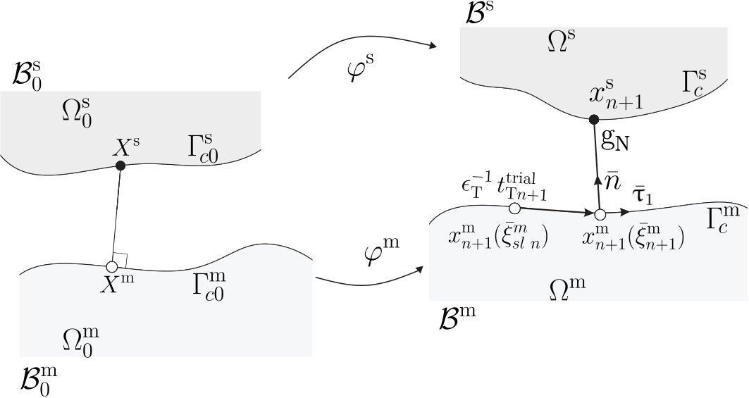 Figure 1
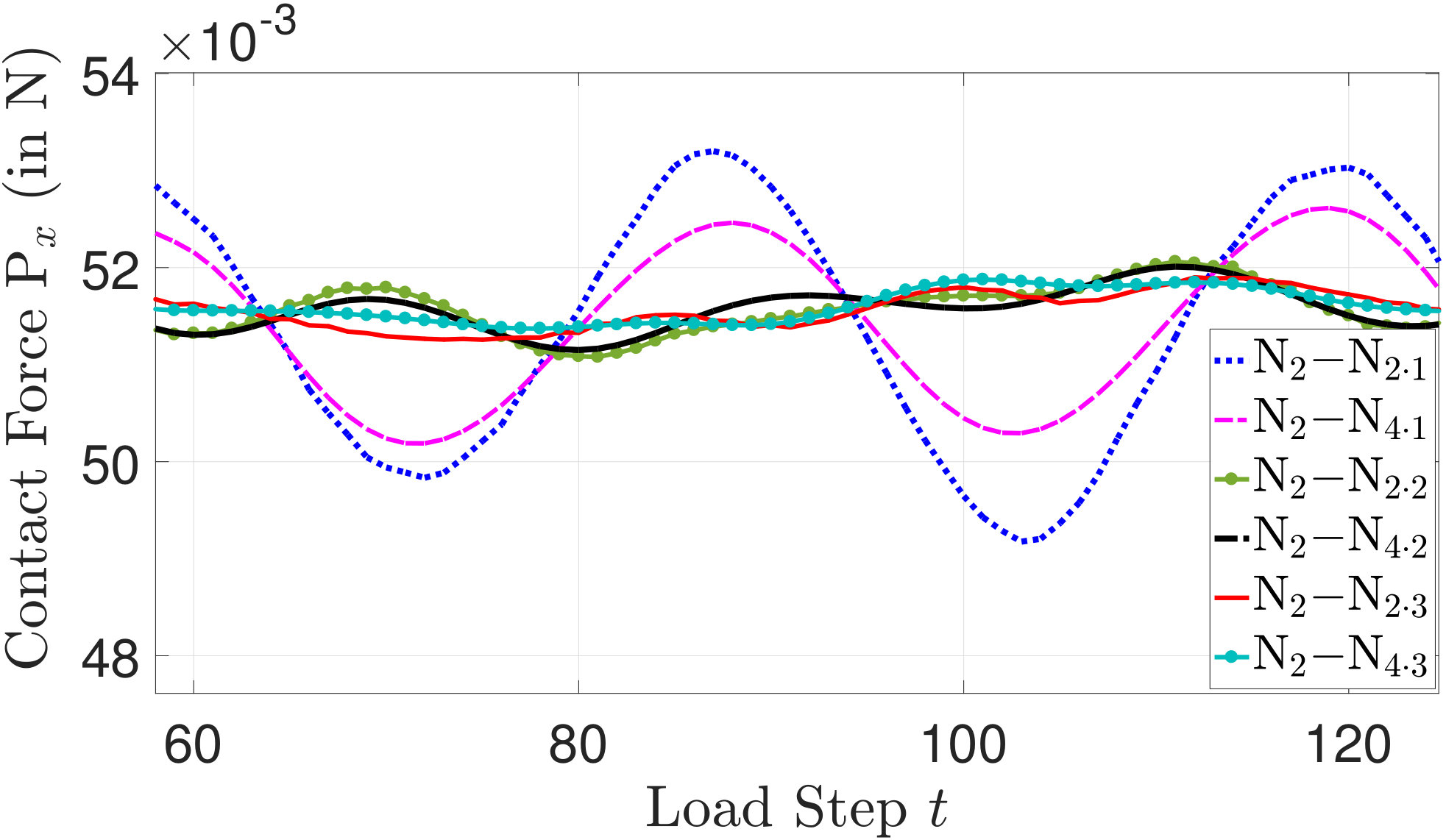 Figure 10
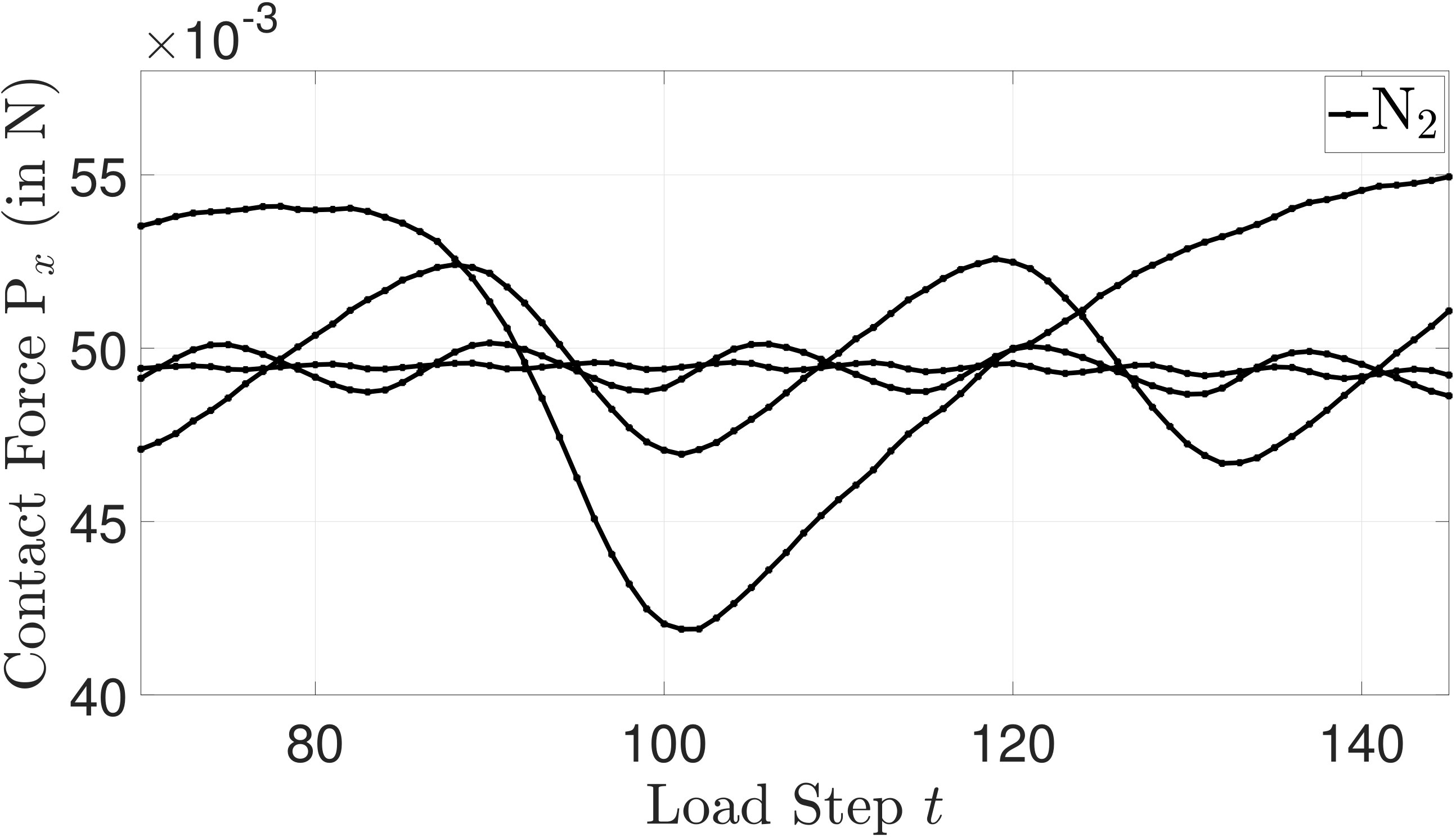 Figure 11
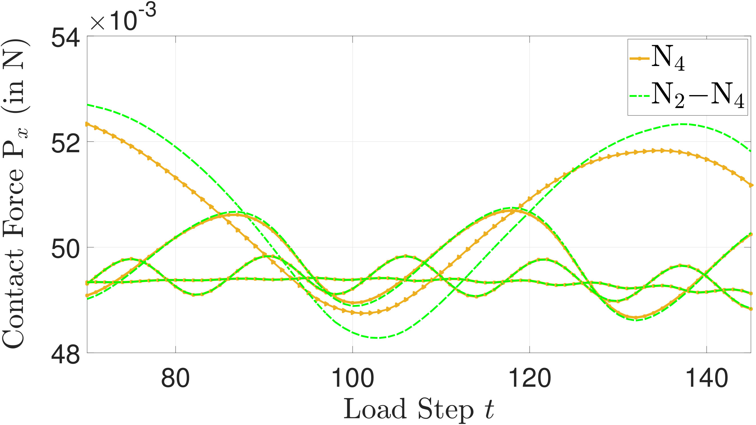 Figure 11
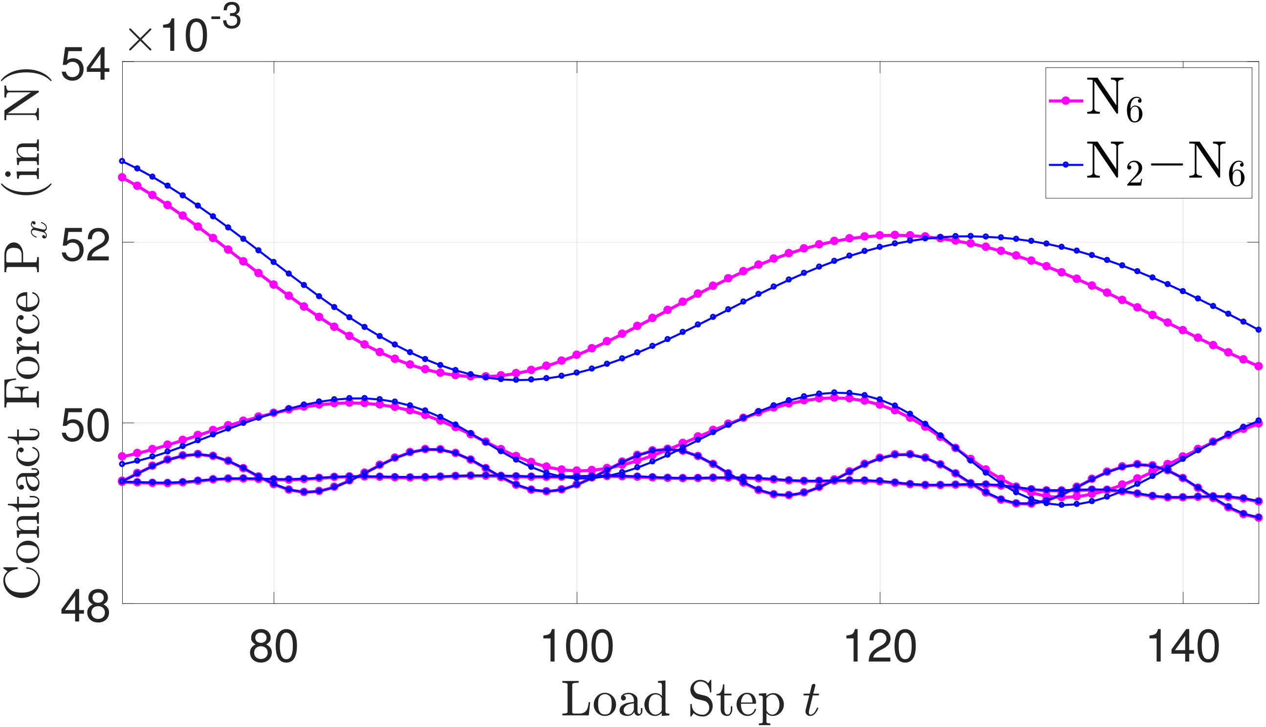 Figure 11
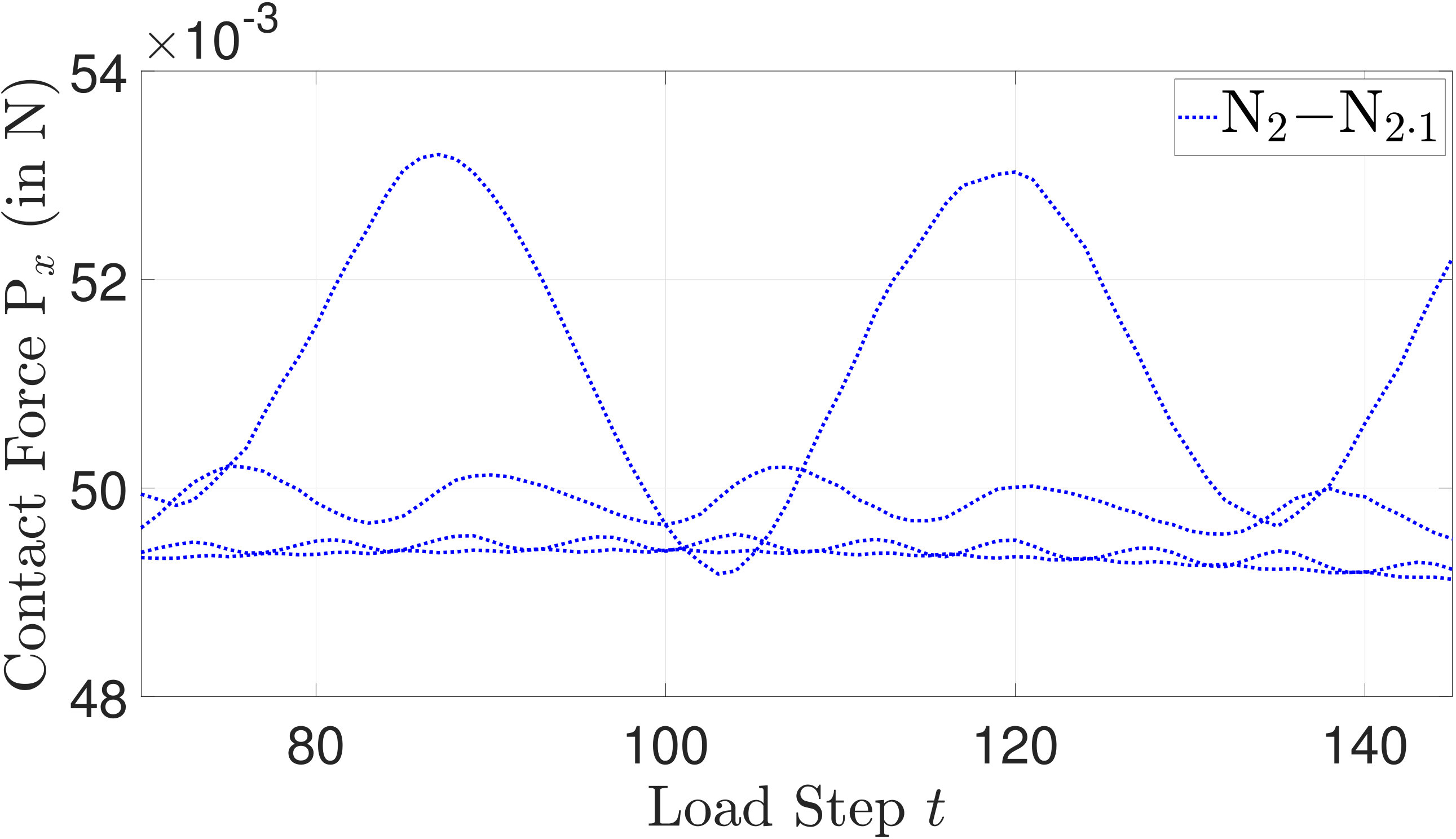 Figure 11
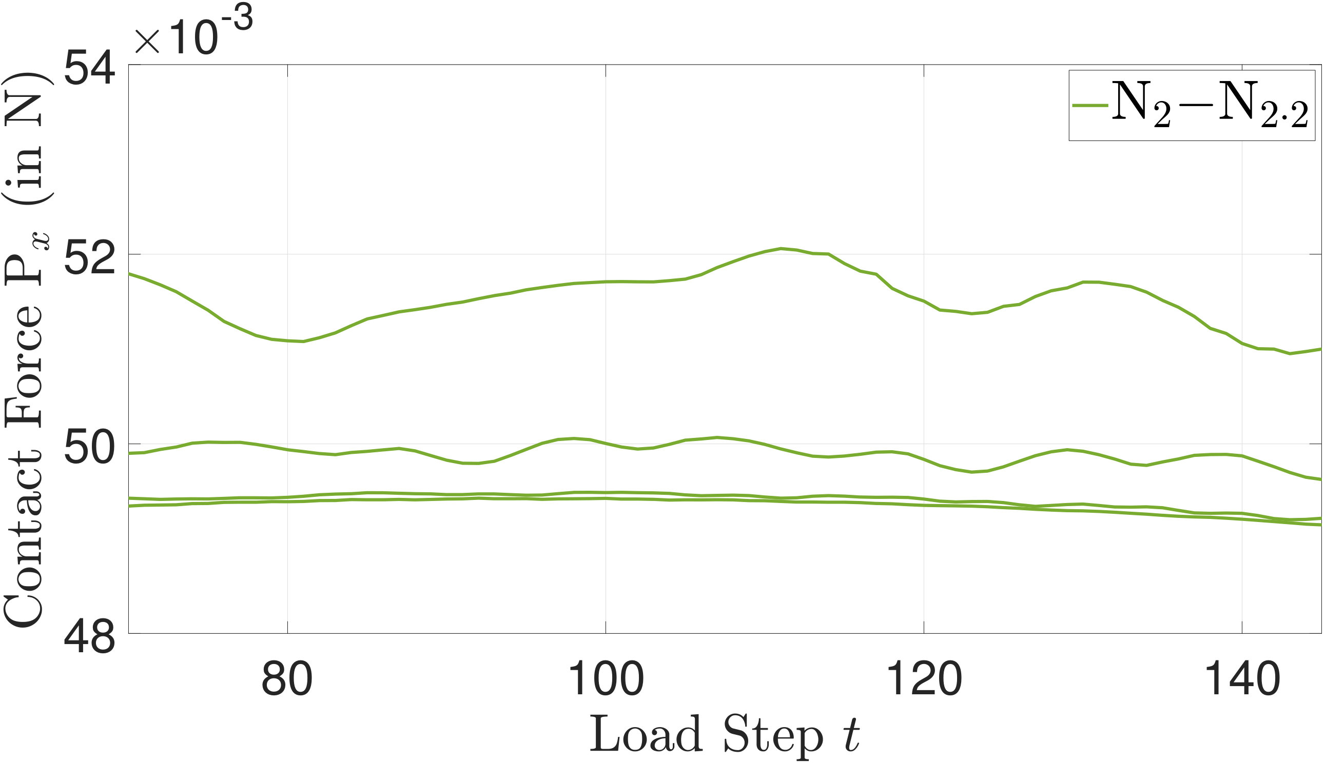 Figure 11
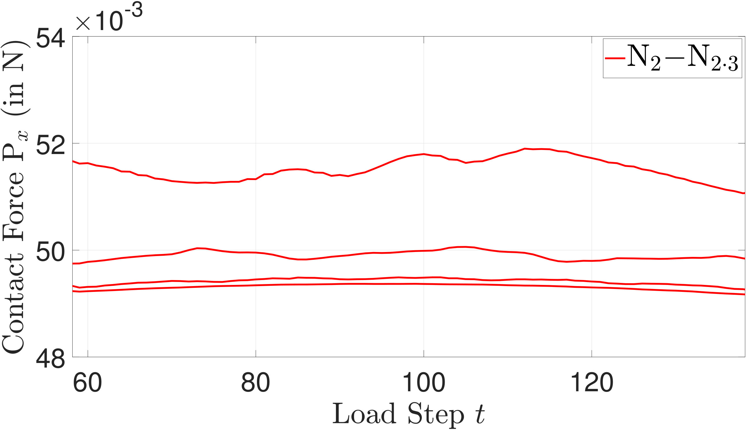 Figure 11
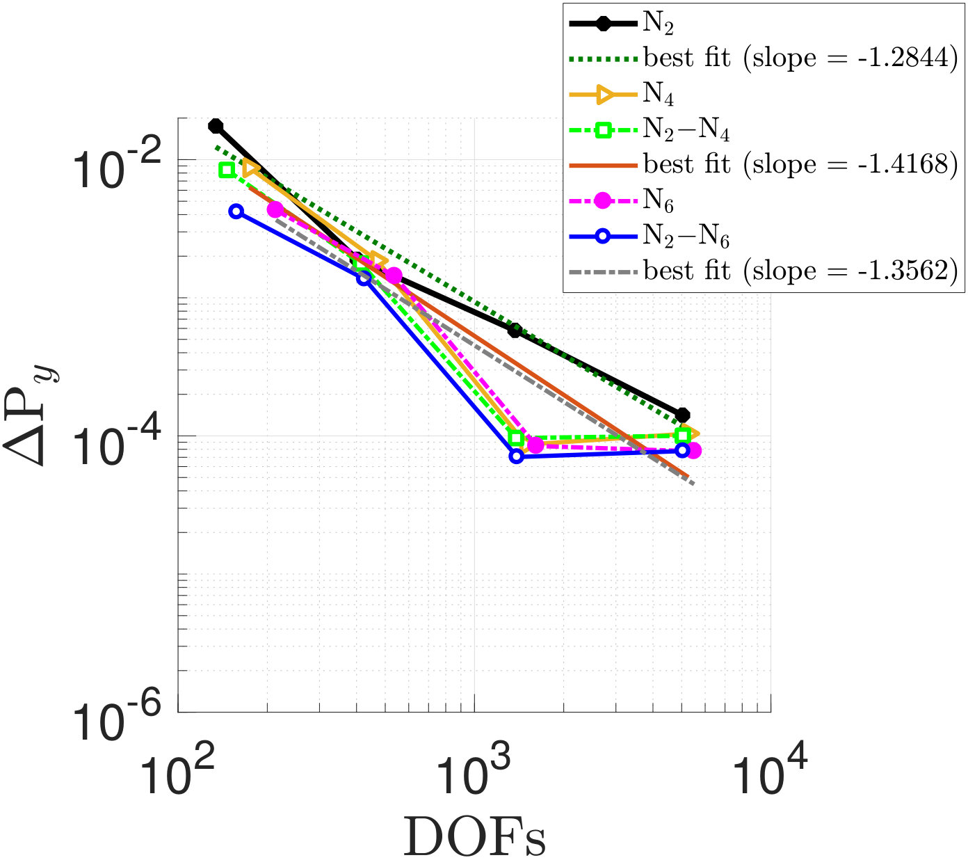 Figure 12
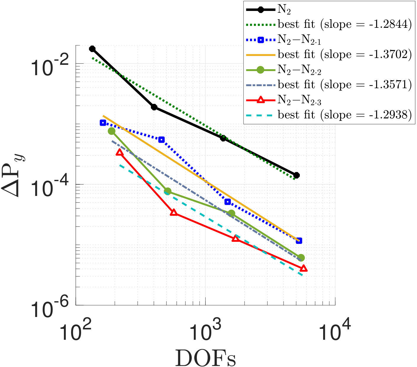 Figure 12
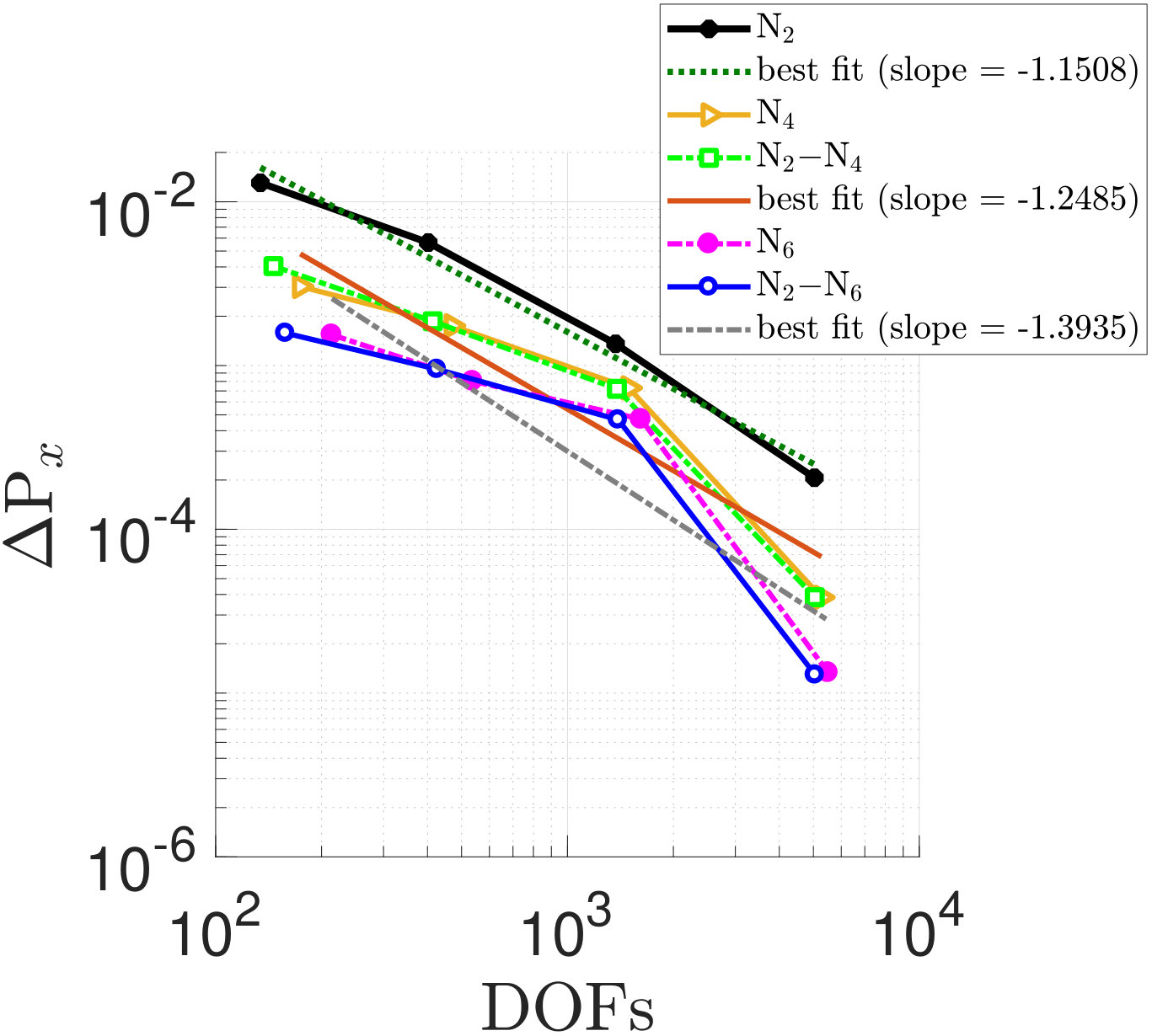 Figure 12
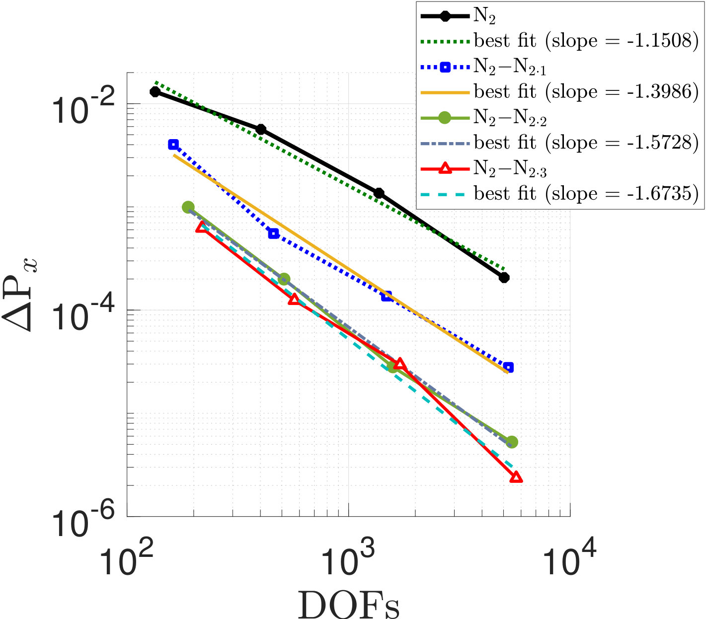 Figure 12
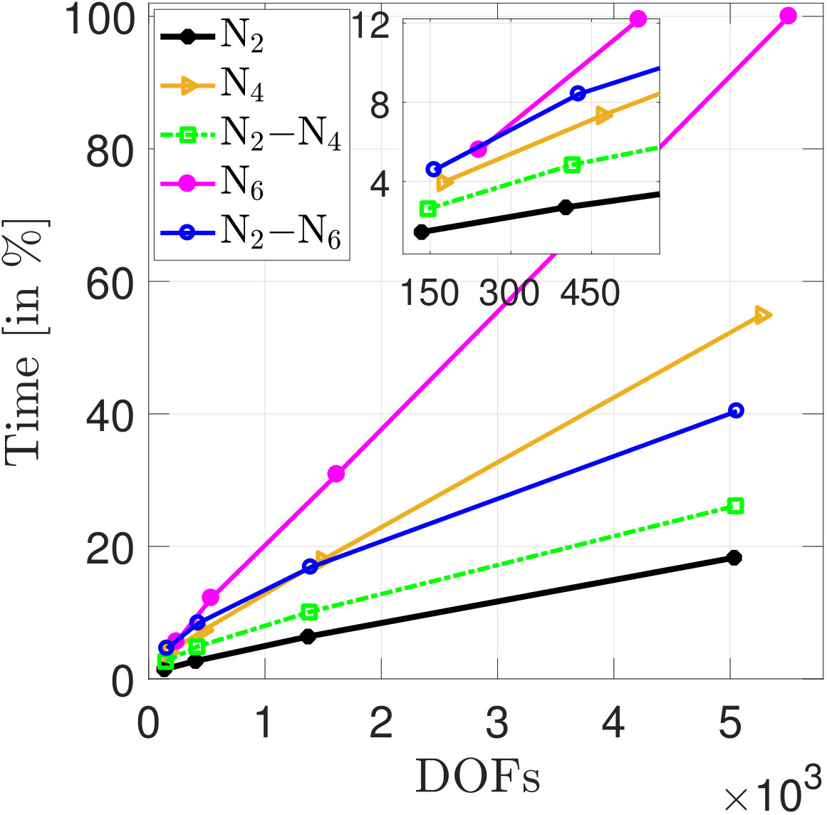 Figure 13
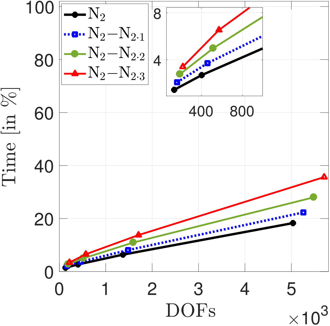 Figure 13
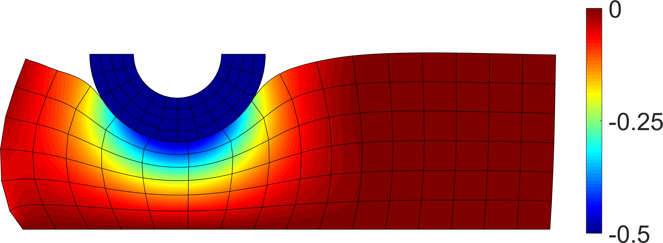 Figure 14
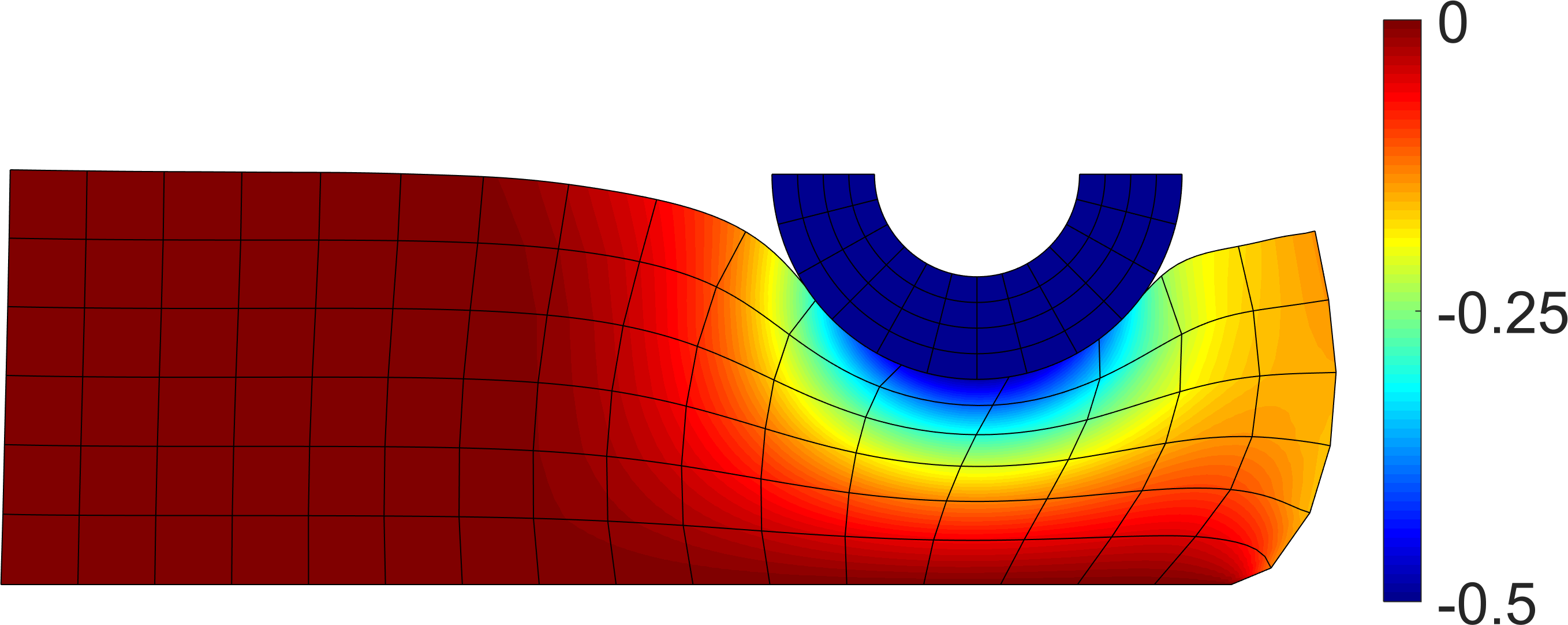 Figure 14
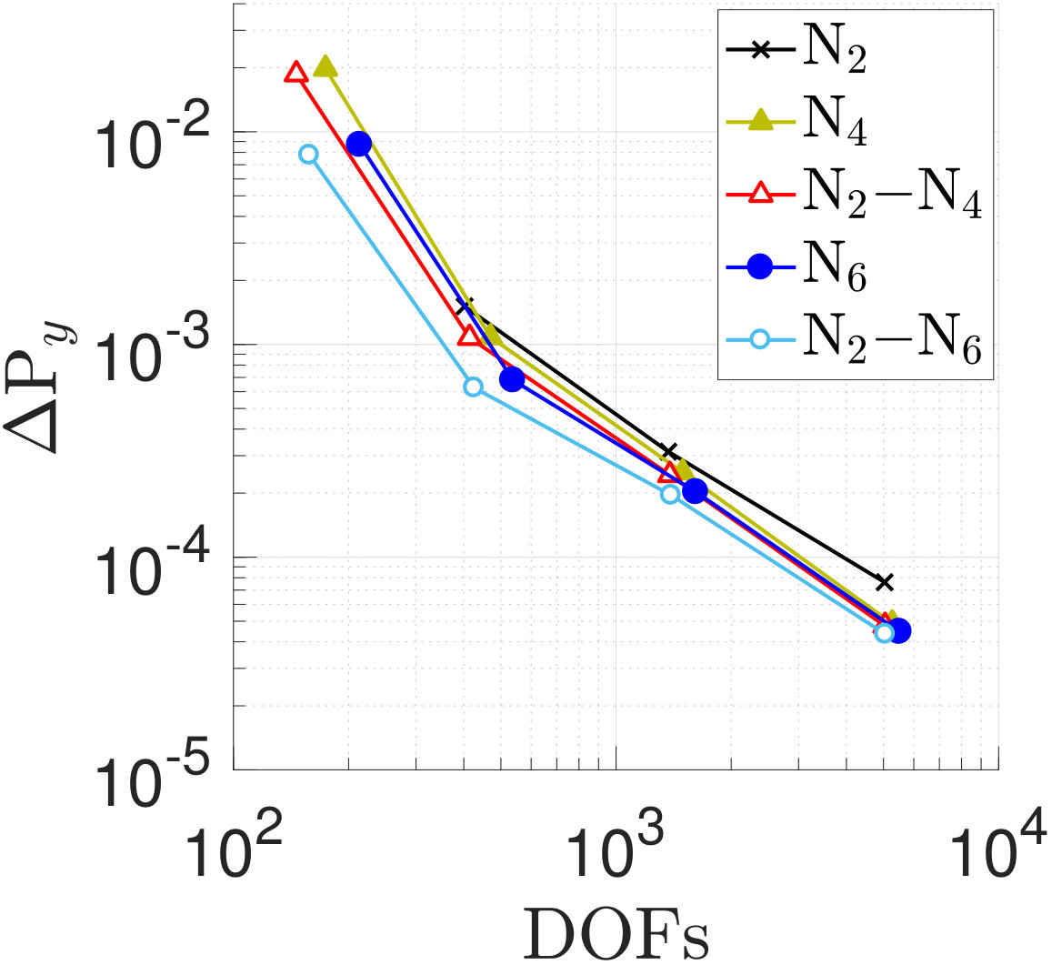 Figure 15
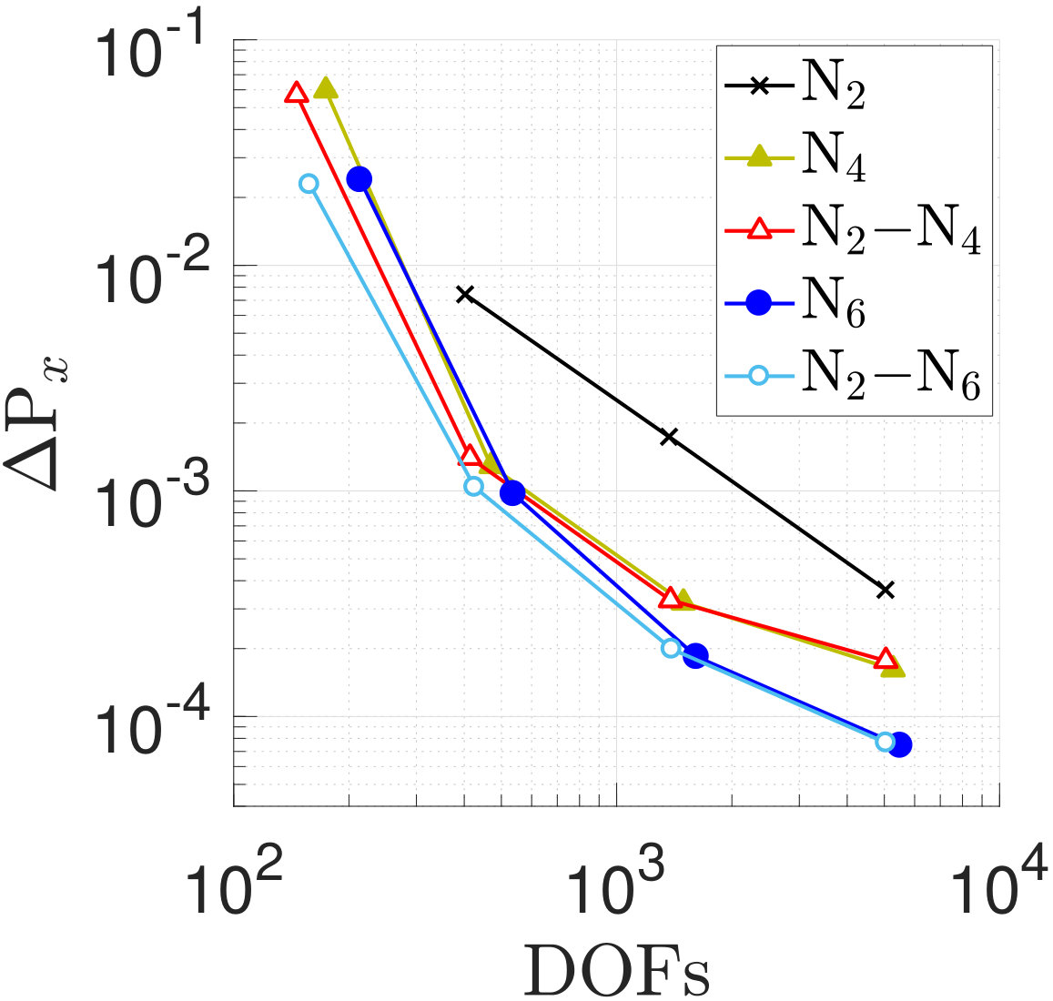 Figure 15
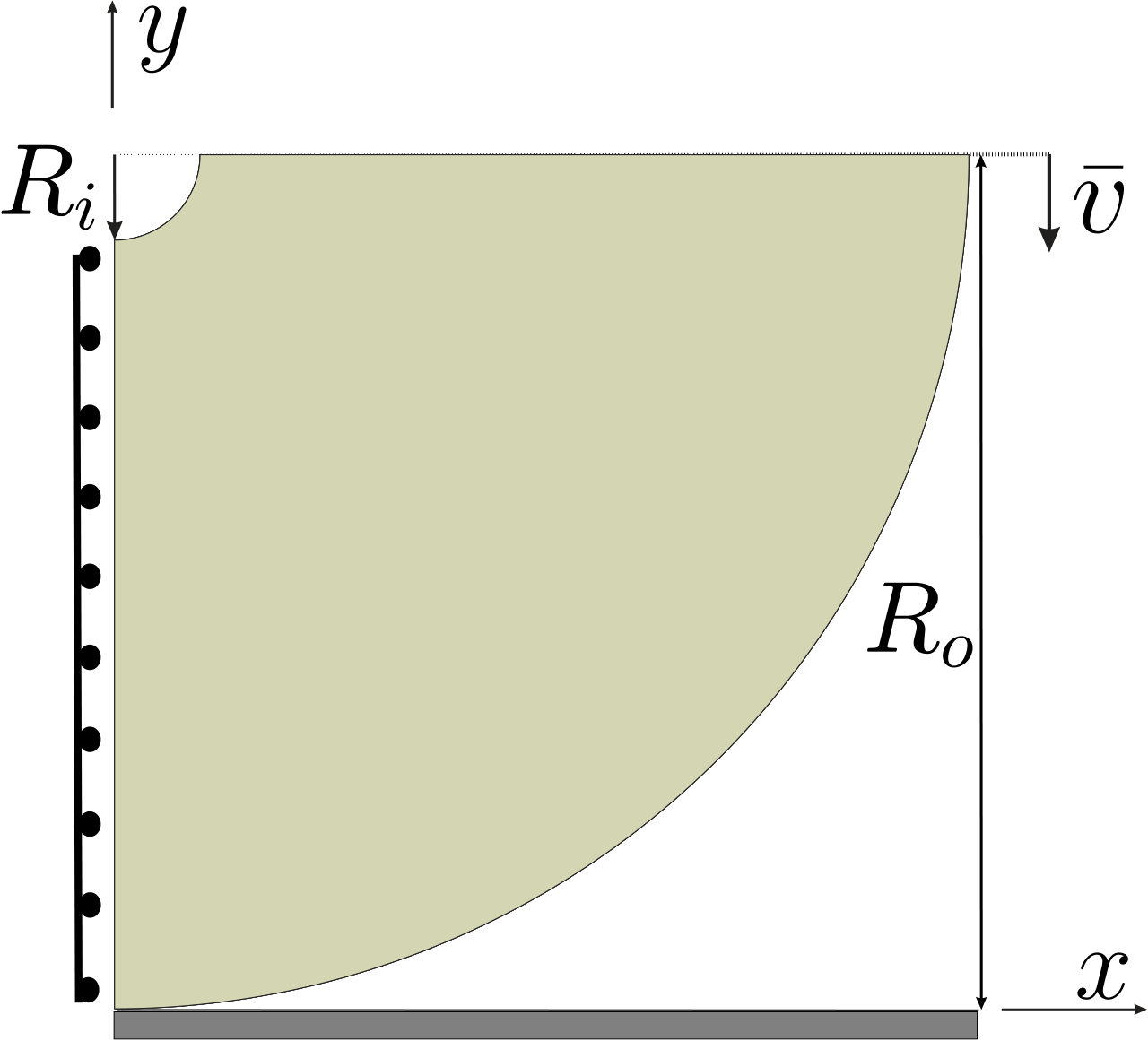 Figure 16
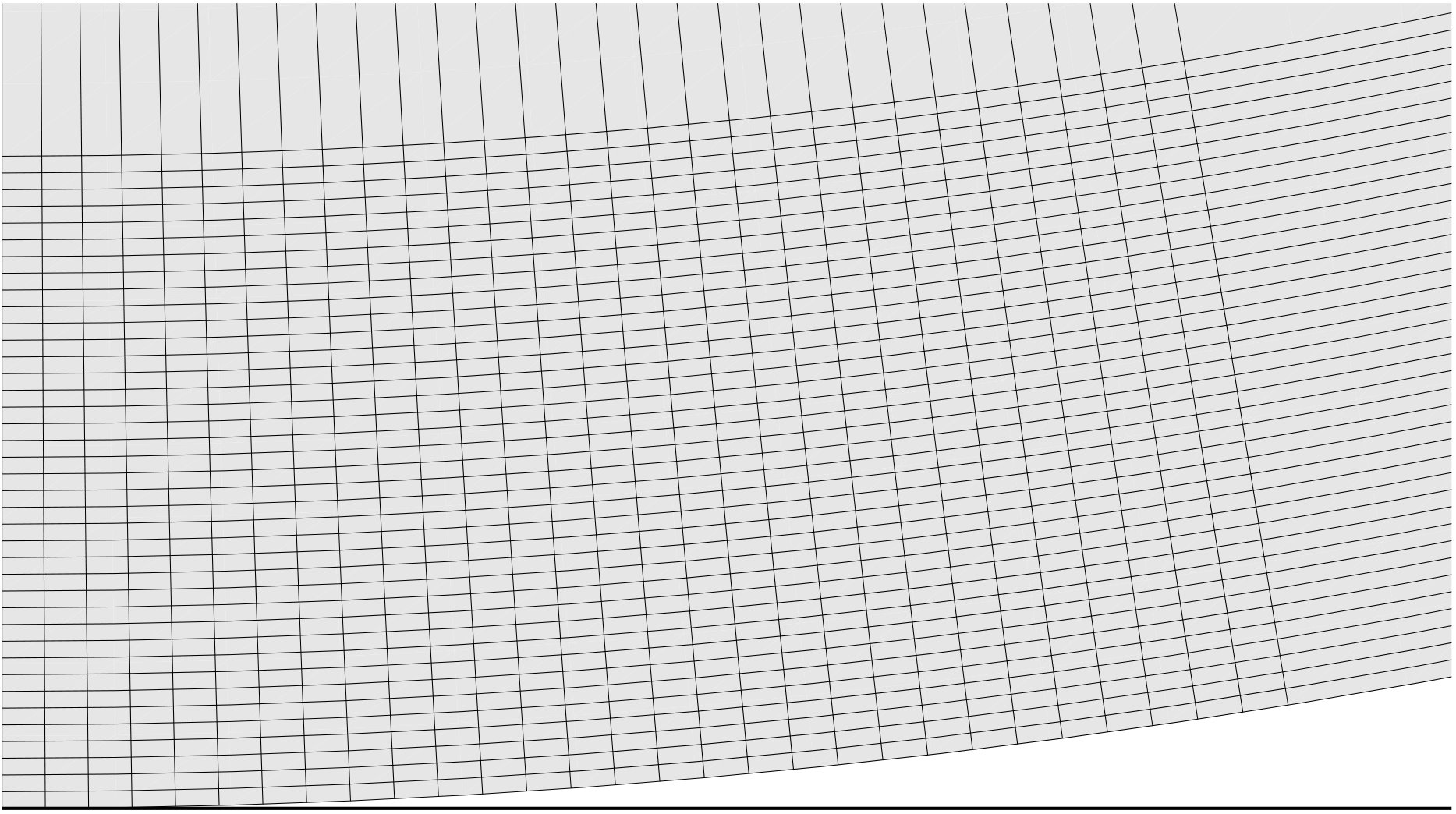 Figure 17
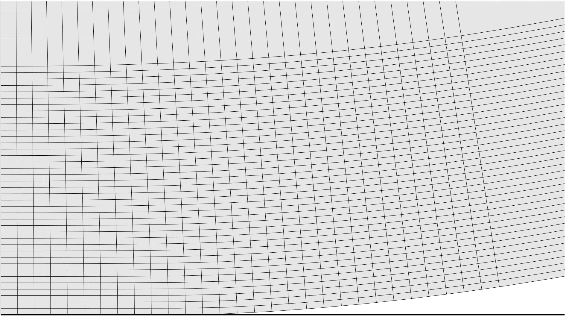 Figure 17
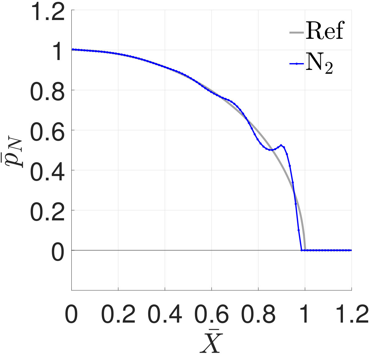 Figure 18
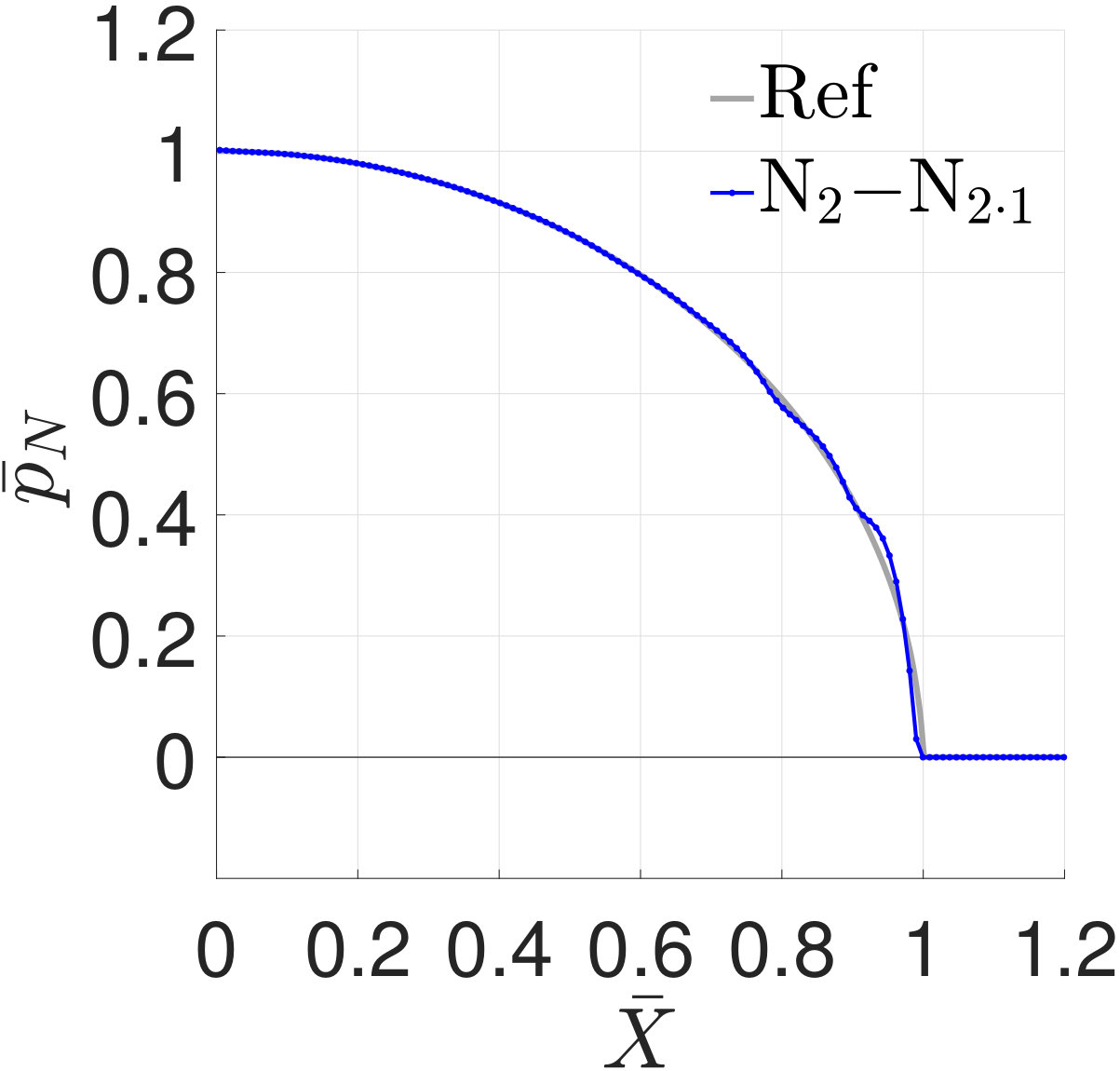 Figure 18
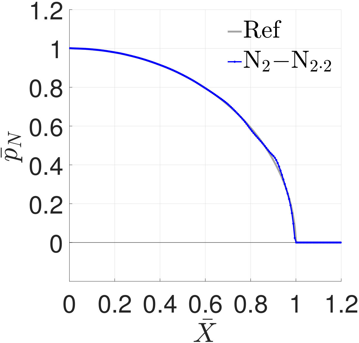 Figure 18
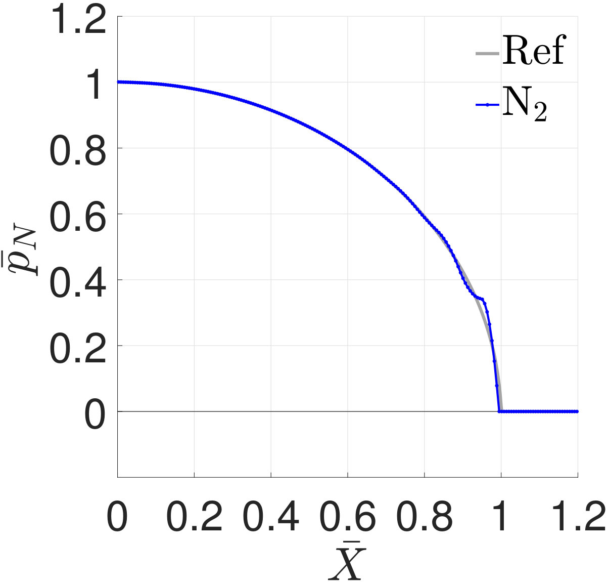 Figure 18
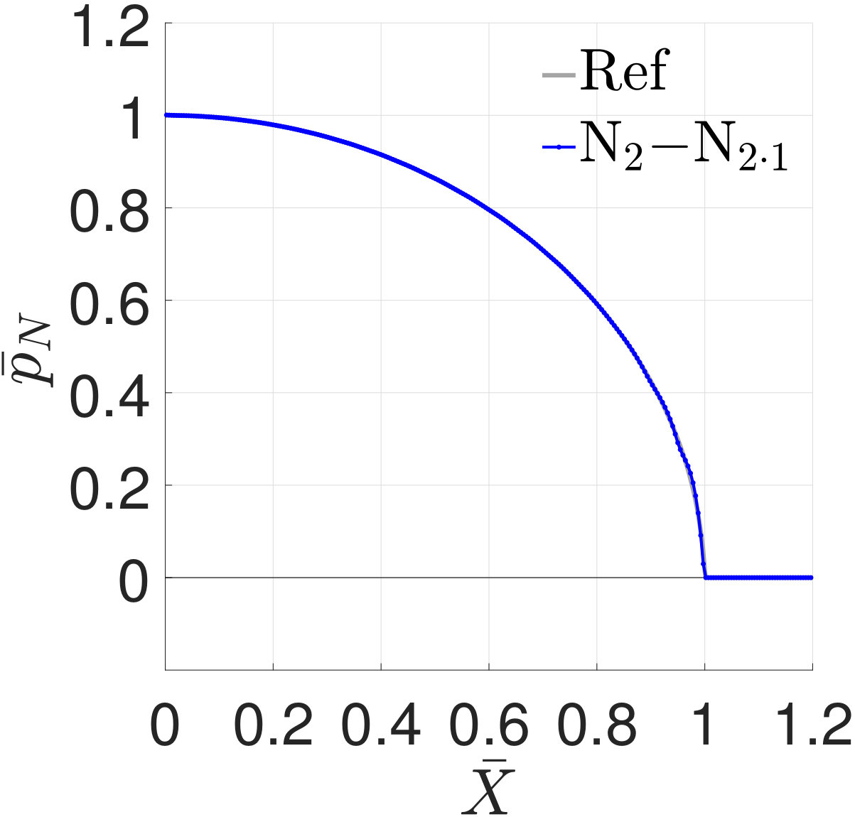 Figure 18
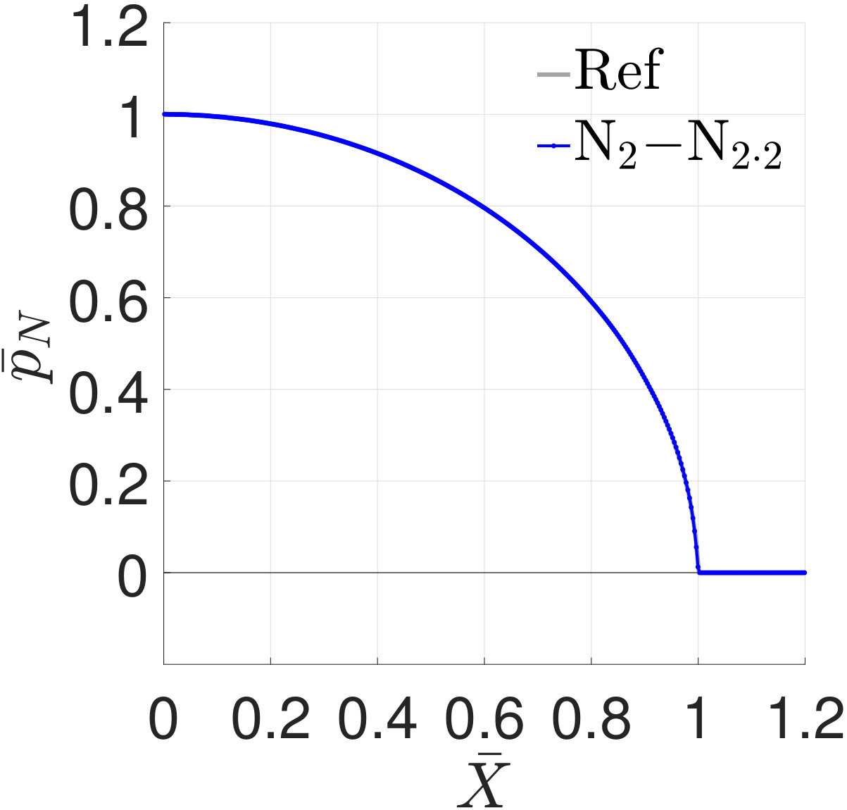 Figure 18
 Figure 18
 Figure 18
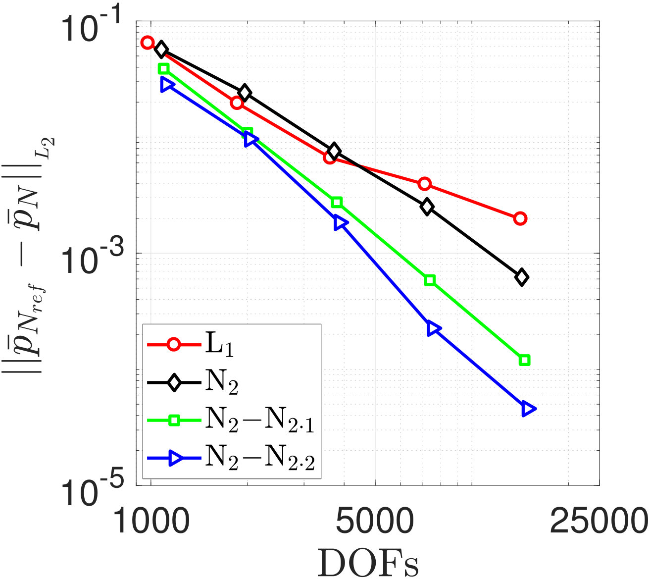 Figure 19
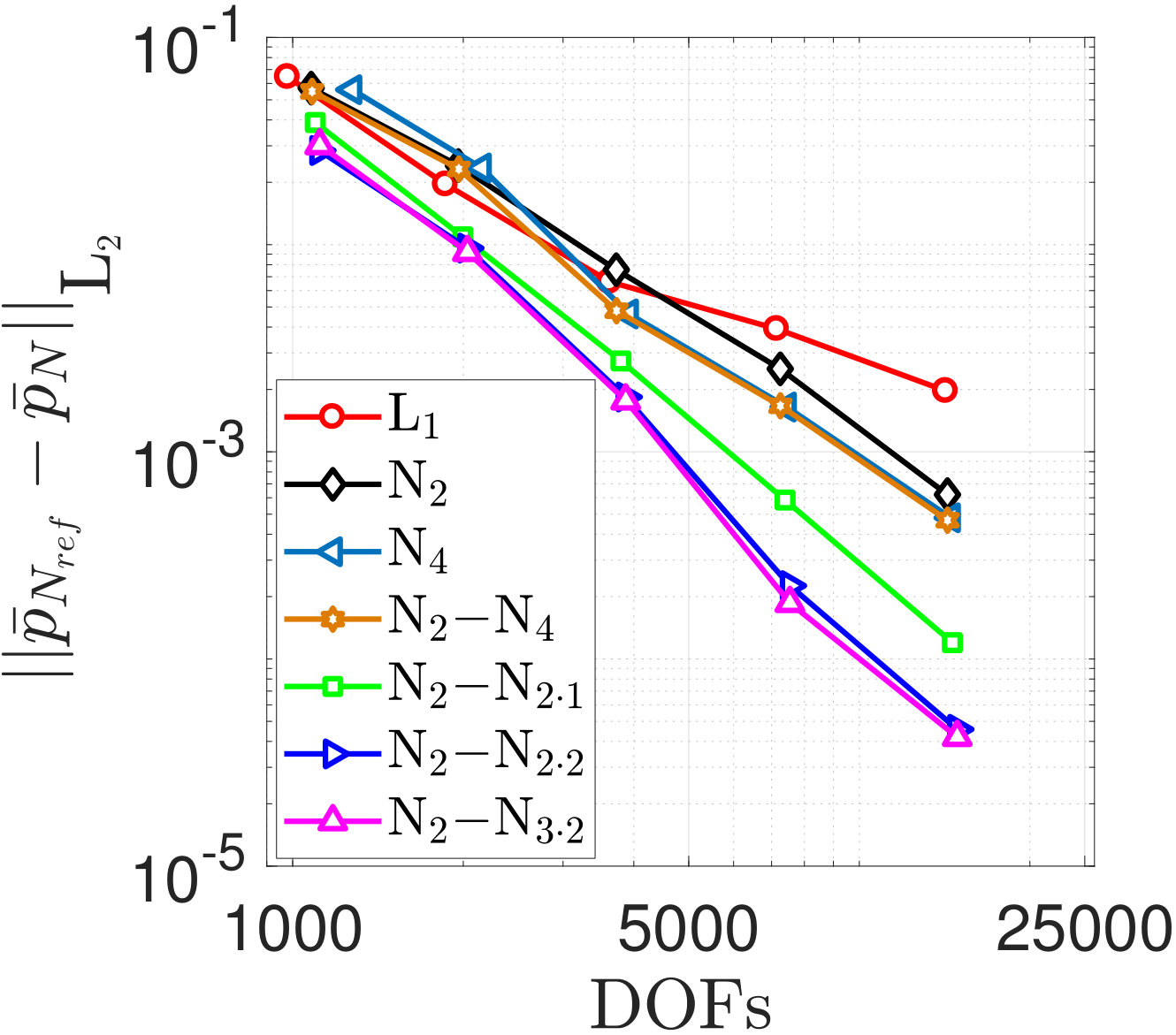 Figure 20
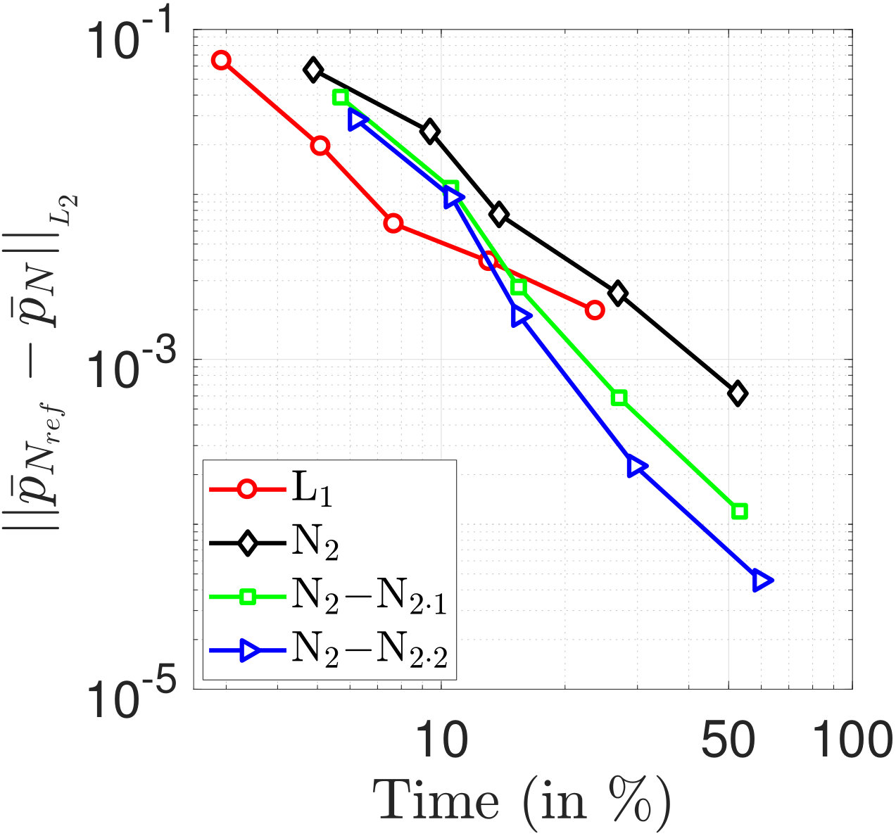 Figure 21
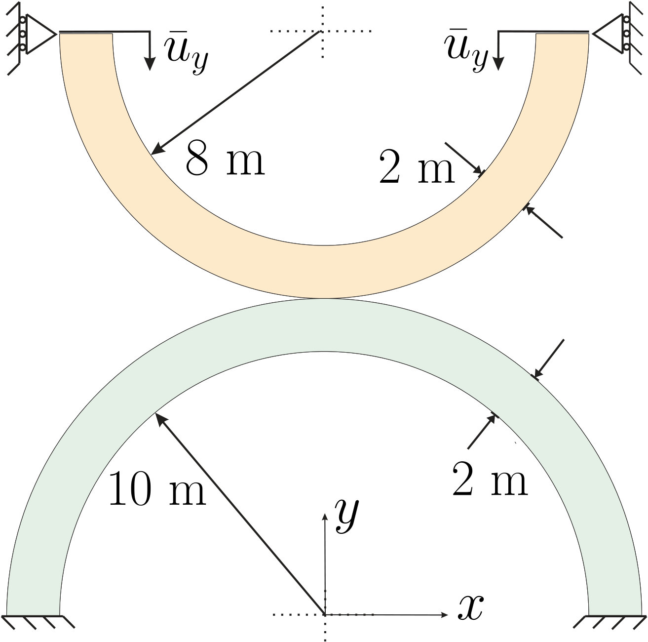 Figure 22
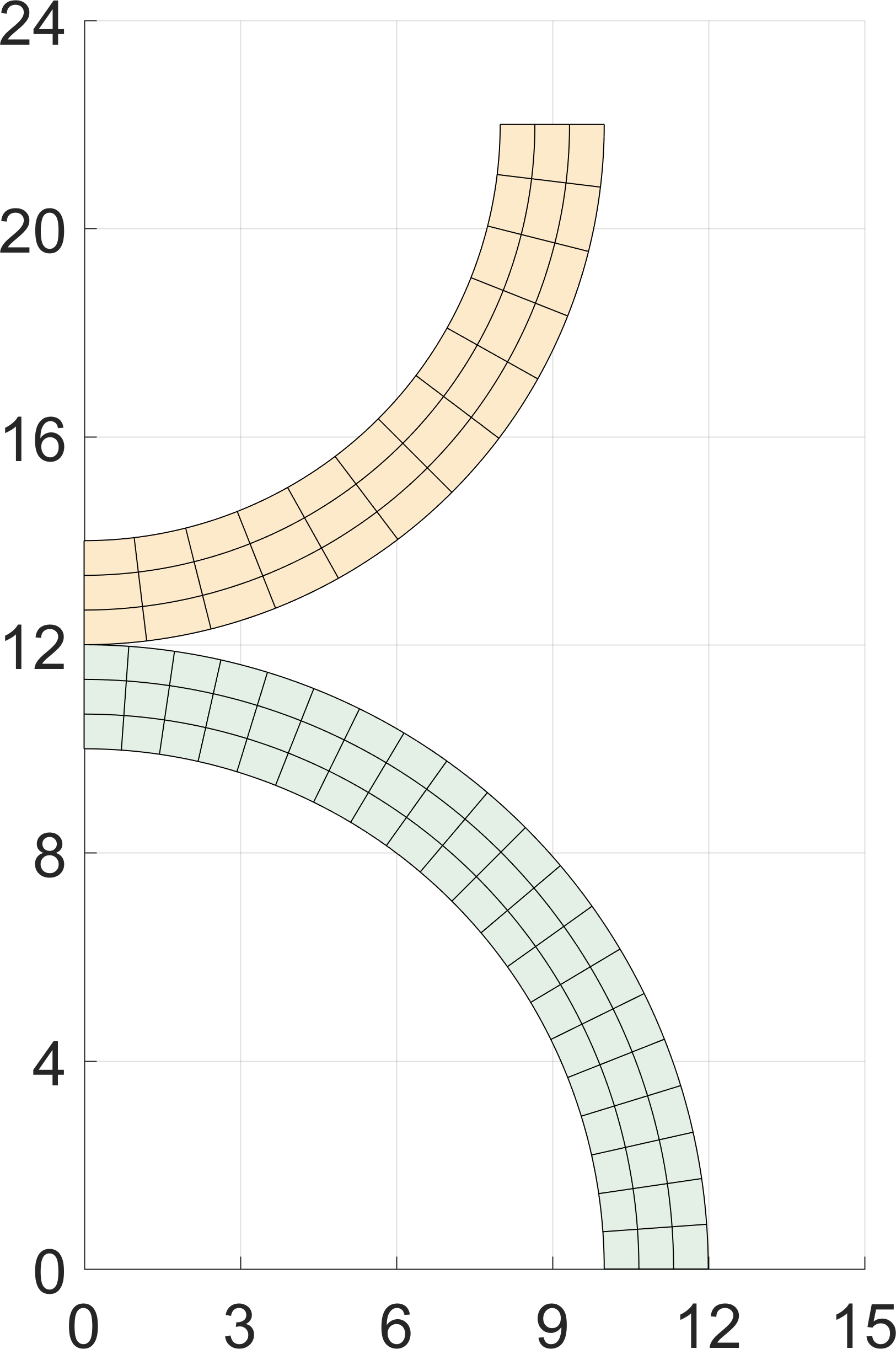 Figure 23
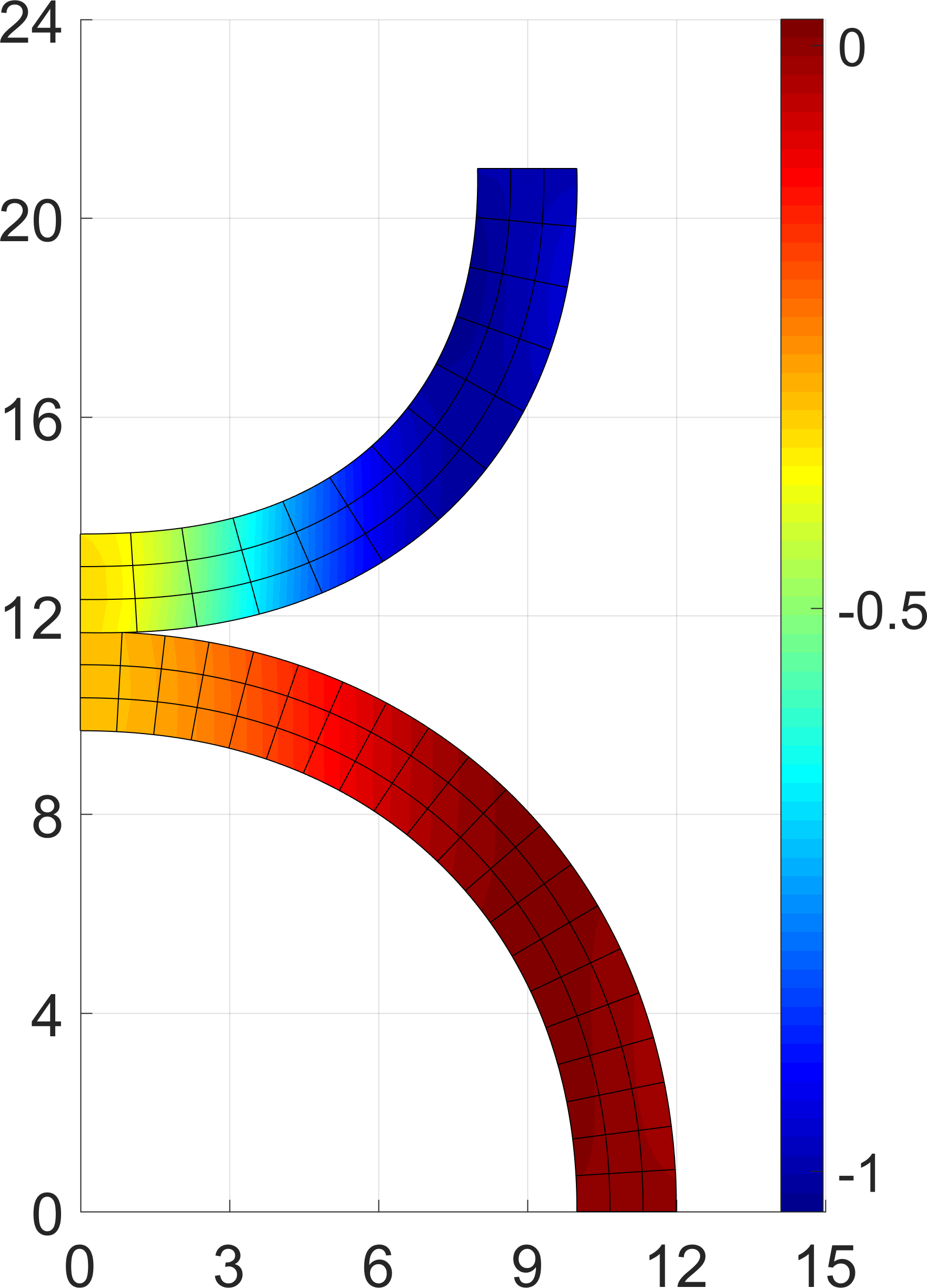 Figure 23
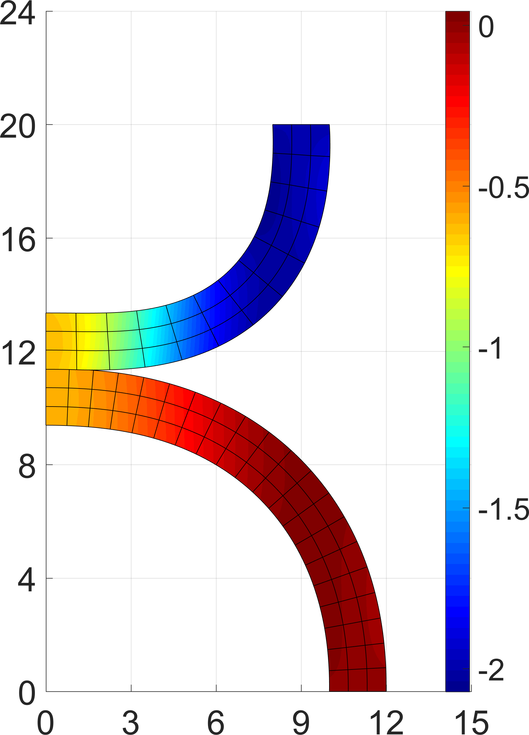 Figure 23
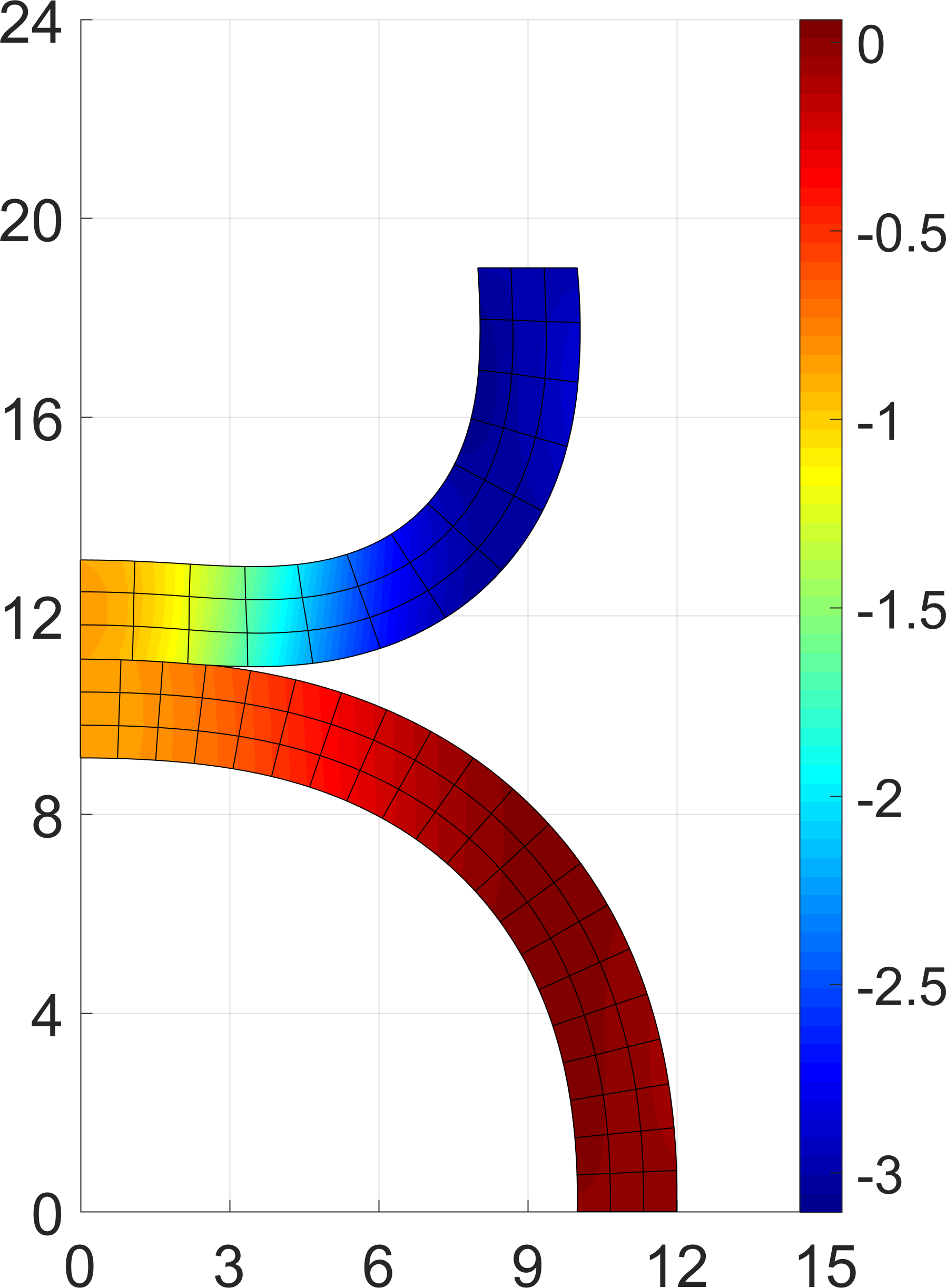 Figure 23
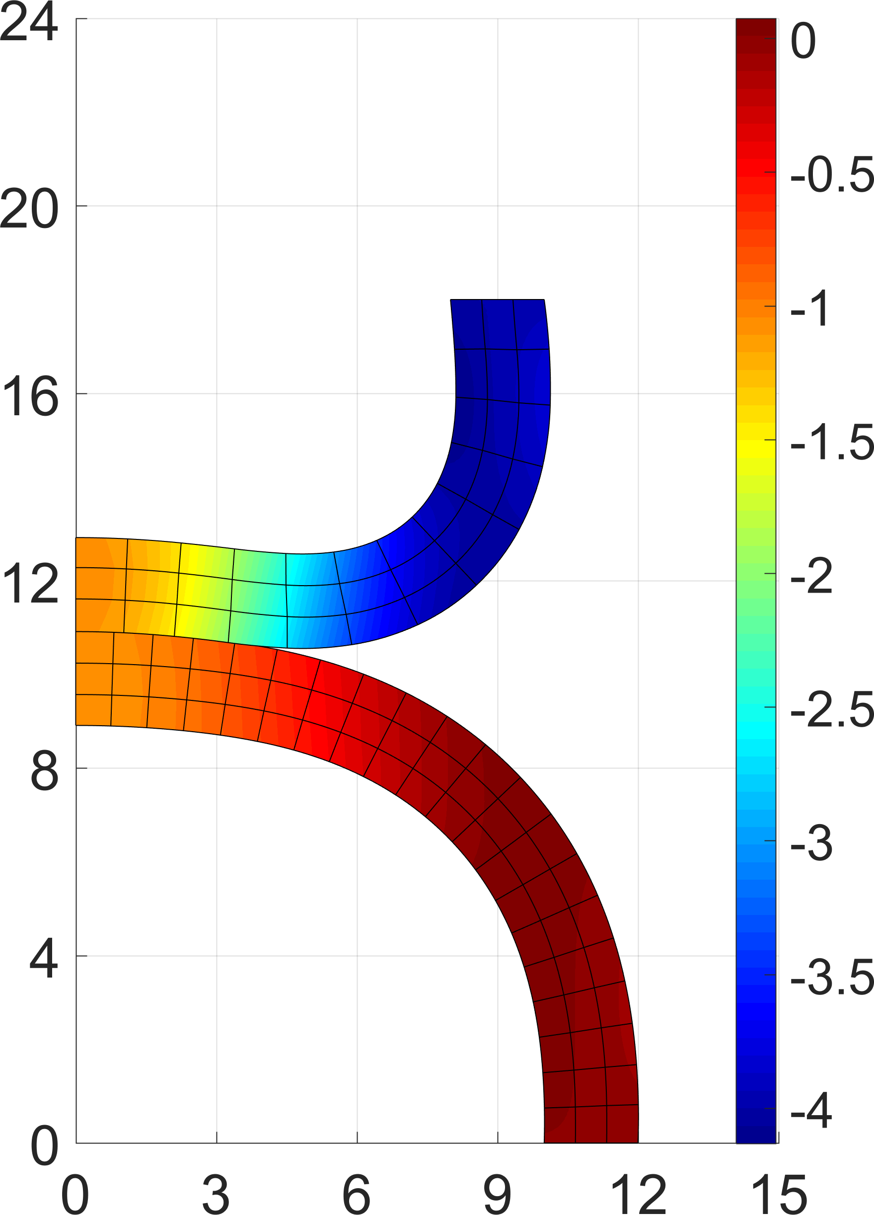 Figure 23
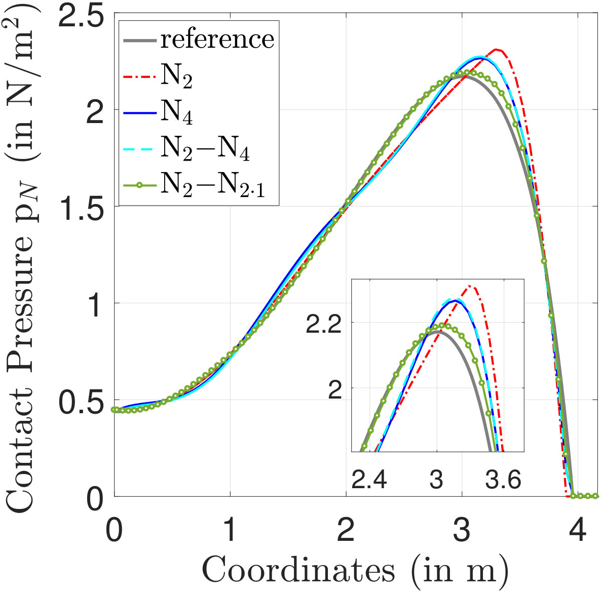 Figure 24
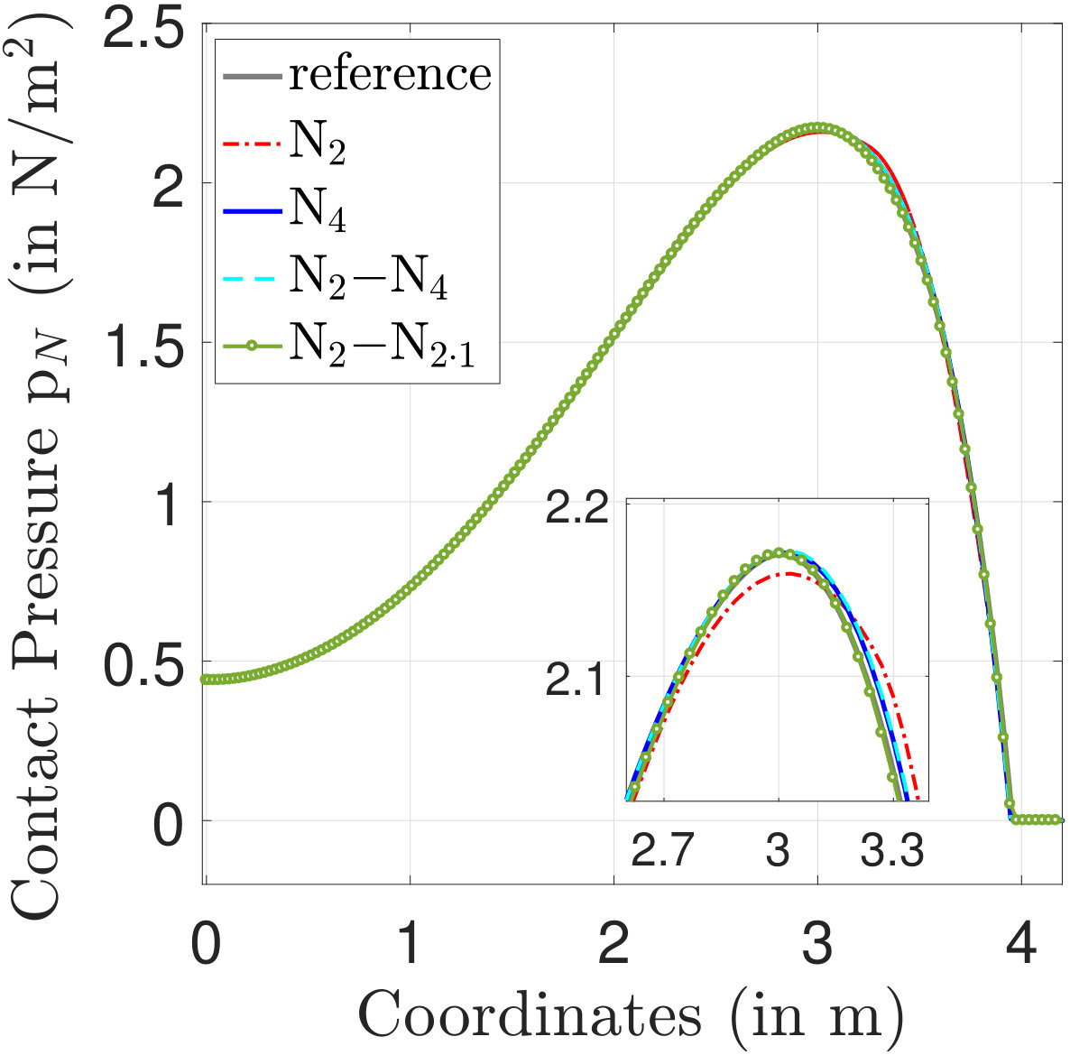 Figure 24
| Mesh | Elements | ||||||
|---|---|---|---|---|---|---|---|
| Die | Slab | ||||||
| m1 | |||||||
| m2 | |||||||
| m3 | |||||||
| m4 | |||||||
| Element | DOF for die | DOF for slab | Total | ||||
|---|---|---|---|---|---|---|---|
| Interface | Bulk | Total | Interface | Bulk | Total | DOF | |
| N2 | 18 | 36 | 54 | 20 | 60 | 80 | 134 |
| N4 | 26 | 52 | 78 | 24 | 72 | 96 | 174 |
| N6 | 34 | 68 | 102 | 28 | 84 | 112 | 214 |
| NN4 | 26 | 36 | 62 | 24 | 60 | 84 | 146 |
| NN6 | 24 | 36 | 70 | 28 | 60 | 88 | 158 |
| NN2⋅1 | 30 | 36 | 66 | 36 | 60 | 96 | 162 |
| NN2⋅2 | 42 | 36 | 78 | 52 | 60 | 112 | 190 |
| NN2⋅3 | 54 | 36 | 90 | 68 | 60 | 128 | 218 |
| Element | ||||
|---|---|---|---|---|
| N2 | 100 | 100 | ||
| N4 | 49.88 | 23.31 | ||
| N6 | 24.57 | 11.81 | ||
| NN4 | 48.11 | 27.02 | ||
| NN6 | 23.83 | 12.09 | ||
| NN2⋅1 | 5.98 | 30.84 | ||
| NN2⋅2 | 4.31 | 7.51 | ||
| NN2⋅3 | 1.89 | 4.77 |
| Mesh | Discretizations | DOFs | ||||||
|---|---|---|---|---|---|---|---|---|
| Interface | Bulk | Total | ||||||
| L1 | 20 | 960 | 980 | |||||
| m1 | N2 | 22 | 1056 | 1078 | ||||
| NN2⋅1 | 40 | 1056 | 1096 | |||||
| NN2⋅2 | 58 | 1056 | 1114 | |||||
| L1 | 38 | 1824 | 1862 | |||||
| m2 | N2 | 40 | 1920 | 1960 | ||||
| NN2⋅1 | 76 | 1920 | 1996 | |||||
| NN2⋅2 | 112 | 1920 | 2032 | |||||
| L1 | 74 | 3552 | 3626 | |||||
| m3 | N2 | 76 | 3648 | 3724 | ||||
| NN2⋅1 | 148 | 3648 | 3796 | |||||
| NN2⋅2 | 220 | 3648 | 3868 | |||||
| L1 | 146 | 7008 | 7154 | |||||
| m4 | N2 | 148 | 7104 | 7252 | ||||
| NN2⋅1 | 292 | 7104 | 7396 | |||||
| NN2⋅2 | 436 | 7104 | 7540 | |||||
| L1 | 290 | 13920 | 14210 | |||||
| m5 | N2 | 292 | 14016 | 14308 | ||||
| NN2⋅1 | 580 | 14016 | 14596 | |||||
| NN2⋅2 | 868 | 14016 | 14884 | |||||
| m6 | N2 | 580 | 27840 | 28420 | ||||
| Discretization | |||||
|---|---|---|---|---|---|
| m1 | m2 | m1 | m2 | ||
| N2 | |||||
| N4 | |||||
| NN4 | |||||
| NN2⋅1 | |||||
| Discretization | Time | ||
|---|---|---|---|
| m1 | m2 | ||
| N2 | |||
| N4 | |||
| NN4 | |||
| NN2⋅1 | |||
Peer Reviews
No public reviews on file for this paper yet. If you reviewed it on a platform where reviews are public (OpenReview, ICLR, NeurIPS, ICML), you can paste yours below so the community can read it here.
Videos
No videos yet. Explain this paper in a talk, walkthrough, or lecture? Add one.
Varying-order NURBS discretization: An accurate and efficient method for isogeometric analysis of large deformation contact problems
Vishal Agrawal
Published222This pdf is the personal version of an article (with minor corrections) whose final publication is available at https://www.journals.elsevier.com/computer-methods-in-applied-mechanics-and-engineering in: Computer Methods in Applied Mechanics and Engineering
DOI:10.1016/j.cma.2020.113125,
Submitted: 27 Nov. 2019, Accepted: 8 May 2020
Sachin S. Gautam111Corresponding author email: [email protected]
Published222This pdf is the personal version of an article (with minor corrections) whose final publication is available at https://www.journals.elsevier.com/computer-methods-in-applied-mechanics-and-engineering in: Computer Methods in Applied Mechanics and Engineering
DOI:10.1016/j.cma.2020.113125,
Submitted: 27 Nov. 2019, Accepted: 8 May 2020
Abstract
A novel varying-order based NURBS discretization method is proposed to enhance the performance of isogeometric analysis (IGA) technique within the framework of computational contact mechanics. The method makes use of higher-order NURBS for the contact integral evaluations. The minimum orders of NURBS capable of representing the complex geometries exactly are employed for the bulk computations. The proposed methodology provides a possibility to refine the geometry through controllable order elevation for isogeometric analysis. To achieve this, a higher-order NURBS layer is used as the contact boundary layer of the bodies. The NURBS layer is constructed using different surface refinement strategies such that it is accompanied by a large number of additional degrees of freedom and matches with the bulk parameterization.
The capabilities and benefits of the proposed method are demonstrated using the two-dimensional frictionless and frictional contact problems, considering both small and large deformations. The results with the existing fixed-order based NURBS discretizations are used for comparisons. Numerical examples show that with the proposed method, a much higher accuracy can be achieved even with a coarse mesh as compared to the existing NURBS discretization approach. It exhibits a major gain in the numerical efficiency without the loss of stability, robustness, and the intrinsic features of NURBS-based IGA technique for a similar accuracy level. The simplicity of the proposed method lends itself to be conveniently embedded in an existing isogeometric contact code after only a few minor modifications.
Keywords: Computational contact mechanics; Isogeometric analysis; NURBS; Higher-order contact boundary; Frictional contact; Non-linear continuum mechanics
1 Introduction
In the last two decades, non-uniform rational B-splines (NURBS) based isogeometric analysis [1] approach has been established as an advantageous computational technology for various classes of problems, especially to those where the geometric approximation and inaccurate capture of the driving forces at the interface adversely influence the accuracy of the result. For example, in cohesive zone modelling problems [2, 3, 4], estimation of the fatigue life of interfacial cracks in the functionally graded material plates [5, 6, 7], evaluation of through-thickness cracks in homogeneous and isotropic plates [8], in three-dimensional problems having straight and curved crack fronts [9], and for the analysis of cracks in the functionally graded piezoelectric materials [10], etc. This is attributed to the distinguished intrinsic features of its underlying basis function, viz. the ability to represent complex geometry exactly even with a coarse mesh, variational diminishing and convex-hull properties, tailorable inter-element continuity, and non-negativeness [1, 11]. Contact modeling belongs to one of these classes that have particularly been benefited from the aforementioned features of the IGA technology. Higher-order smoothness of the NURBS discretized geometry directly provides the continuous normal vector field across the boundary of the contact elements. Thus, it eliminates the need for additional contact surface smoothening approaches [12, 13, 14, 15, 16, 17] often utilized in the context of the finite element method.
The first investigations on the treatment of contact problems using isogeometric analysis are conducted by Temizer et al. [18, 19], Lu [20], and De Lorenzis et al. [21, 22].
Temizer et al. [18] applied the isogeometric analysis to three-dimensional thermomechanical frictionless contact using the mortar contact formulation. For the regularization of the contact constraints, the penalty method is adopted. They demonstrated that NURBS based discretization achieves superior results in terms of quality and robustness over its counterpart Lagrange-polynomial based discretization. However, a very fine mesh is still required to get the result that closely matches with the exact solution. Moreover, the non-mortar contact formulation is found to be over-constrained in nature and leads to inaccurate results. Lu [20] combined the isogeometric analysis with the segment-to-segment based contact formulation presented by Papadopoulos and Taylor [23]. He showed that intrinsically smooth NURBS discretized geometry alleviates the non-physical oscillations of the contact forces and is capable of accurately describing the intricate mechanics of smooth materials such as fabrics. De Lorenzis et al. [21] introduced a mortar-based contact formulation in the context of IGA for the investigation of two-dimensional large deformation contact with Coulomb friction. They demonstrated that the magnitude of the non-physical oscillations of the normal and tangential contact reaction forces reduce on increasing the interpolation order of NURBS discretization. They also showed that the oscillation error in the Hertzian contact stress at the boundary of the contact region is reduced if a very fine mesh is used. Moreover, the distributions of the contact responses obtained with the Lagrange-polynomial based discretizations are found to be highly sensitive to the interpolation order. Later, De Lorenzis et al. [22] applied IGA to three-dimensional large deformation frictionless contact with the mortar method. The contact constraints are enforced using the augmented-Lagrangian approach [24]. Temizer et al. [19] introduced a three-dimensional mortar-based frictional contact formulation as an extension of works in [18, 21]. Again, it is shown that on increasing the interpolation order of the NURBS discretization the smoothness of contact forces improves across the contact interface. A point-to-segment contact formulation for two-dimensional frictionless contact is presented by Matzen et al. [25], and recently extended to a weighted point-based contact approach for three-dimensional contact [26], both with the IGA. Many researchers have extensively studied the application of mortar method in the context of IGA [27, 28, 29, 30, 31, 32], e.g. Brivadis et al. [30] investigated the isogeometric mortar method from the theoretical as well as the numerical point of view. Seitz et al. [31] developed a dual mortar method for isogeometric contact analysis and analyzed the spatial rate of convergence for the mesh tying and contact problems. Recently, Duong et al. [32] introduced a segmentation-free isogeometric mortar contact formulation. A number of works have explored the application of collocation methods to different contact problems using IGA, e.g. [33, 34, 35]. De Lorenzis et al. [36] presented a comprehensive overview on the growth of various isogeometric based treatment procedures and their advantages for contact mechanics as compared to traditional finite element analysis.
From the above-reviewed literature on contact modeling using IGA, it is evident that NURBS-based discretization delivers significantly superior performance in terms of accuracy, stability, and robustness over Lagrange-polynomial based discretization. This is due to the aforementioned distinguished intrinsic features of the NURBS over the Lagrange polynomials. However, the application of the existing NURBS-based discretization approach to isogeometric contact analysis is computationally expensive since due to the rigid tensor nature of the NURBS structures, the underlying mesh can be refined only in a global manner. Moreover, the interpolation order of NURBS functions employed for the discretization of the contact boundary layer and for the remaining bulk domain of the body can only be elevated uniformly. From the analysis point of view, this may not be desirable since the accuracy of the contact solution is primarily governed by the description of the contact interface. According to literature, to enable the local mesh refinement in the context of isogeometric contact, T-splines [37, 38, 39, 40, 3, 4], NURBS-based hierarchical refinement [41, 42], and locally refined (LR) NURBS [43] approaches have been adopted. Dimitri et al. [40, 3, 4] employed the T-splines based discretizations for analyzing the frictionless contact, cohesive/contact interface modeling, and mixed-mode debonding problems. Temizer and Hesch [42], and Hesch et al. [41] used the hierarchical NURBS for the treatment of frictionless and frictional contact, respectively. Zimmermann and Sauer [43] introduced LR NURBS for the analysis of contact computations of solids and membranes. However, the idea to refine the geometry through a controllable order elevation strategy remains unexplored, as already noted by Temizer et al. [19].
In the context of finite element contact analysis, a considerable research progress has been made that integrates the intrinsic features of NURBS and higher-order Lagrange polynomials with the standard FE discretization [44, 45, 46, 47, 48, 49]. Corbett and Sauer [44, 45] introduced a NURBS-enriched contact element formulation that combines the geometric smoothness of NURBS with the efficiency characteristic of the FE discretization. The potential contact layer of each finite element is locally replaced by a NURBS layer, resulting in “NURBS-enriched contact finite elements.” Their work is based on the contact element enrichment strategy of Sauer [50, 51], which used higher-order Lagrange and Hermite functions on the contact surface. Konyukhov and Schweizerhof [52, 53, 54] introduced the hierarchical enrichment of the Lagrange functions space, which allows the anisotropic refinement of the contact boundary layer with the higher-order Lagrange polynomial, while the linear order polynomials remain fixed for the construction of the interior domain of a contact body. Later, Maleki-Jebeli et al. [47] proposed a hybrid isogeometric-finite element discretization method where the advantages of NURBS are exploited in two-dimensional cohesive interface contact/debonding. The bulk domain is given by FE discretization. The transition from NURBS to FE discretizations is carried out using the so-called “transition elements”, initially presented in [44]. Otto et al. [48, 55] proposed a coupled FE-NURBS discretization approach where an auxiliary NURBS layer is placed between the contact zone of higher-order FE discretized contacting bodies. In order to tie the NURBS layer with FE discretization, the pointwise and mortar mesh tying approaches are used. Recently, Dias et al. [49] presented a higher-order mortar-based contact element, where the contact interface and bulk are discretized using the FEM. In contrast to the enrichment approach of Corbett and Sauer [44, 45], they used higher-order Lagrange functions as a basis for the discretization of the contact interface, domain, and approximation of the solution field. The NURBS are only used to map the position of FE contact layer nodes.
On the other hand, in the context of isogeometric contact analysis, no such effort that directly allows the controllable order elevation of NURBS discretized structures and accordingly complements the performance of IGA while fully retaining its intrinsic key features has been devoted.
In the present work, we thus propose a novel varying-order (VO) based NURBS discretization method to improve the performance of NURBS-based IGA technique in the framework of computational contact mechanics. In the proposed method, the user-defined higher-order NURBS functions are employed for the contact computations. The minimum-order of NURBS capable of representing the complex geometries exactly are used for the description of overall bulk domain that does not come into contact. To achieve the VO based NURBS discretization, a new higher-order NURBS layer is used as the contact boundary layer of an initially NURBS discretized geometry. This avoids the application of higher-order NURBS in the region away from the contact interface. The layer is constructed using different surface refinement strategies in such a manner that it is accompanied by a large number of additional degrees of freedom across the contact interface and matches with the bulk parameterization. The proposed varying-order based NURBS discretization method is accordingly denoted by NN, where Np is the order of the NURBS functions utilized for the description of the bulk domain and N is the order of NURBS used for the contact boundary layer. Due to its simplicity, the proposed approach can be conveniently embedded into an existing IGA contact code after only a few modifications.
In the this work, the proposed methodology is applied to two-dimensional frictionless and frictional contact problems, considering both small and large deformations. A classical full-pass version of the contact algorithm introduced by Sauer and De Lorenzis [56, 57] is combined with the VO based NURBS discretization method in this work as a first step towards developing a simple yet computationally efficient technique for isogeometric contact analysis. Such a contact algorithm has previously introduced for Lagrange-polynomial based discretizations [58, 49], fixed-order based NURBS discretizations [18, 21, 22, 40, 3, 4] and recently for T-spline based discretizations [40, 3, 4]. The penalty method is employed for the regularization of impenetrability and sticking contact constraints.
The remainder of the paper is structured as follows. In Section 2, the existing geometric modeling procedure using NURBS and the strategies used for the refinement of a NURBS discretized geometry are briefly discussed. Section 3 describes the mathematical formulation for a large deformation contact between two deformable bodies considering friction. The varying-order based NURBS discretization technique and its implementation into the existing IGA contact code are fully described in Section 4. In Section 5, the performance of the proposed method is demonstrated w.r.t. fixed-order based NURBS discretizations using various numerical examples. Finally, Section 6 concludes the paper with future directions.
2 Preliminaries
In this section, we briefly discuss the existing NURBS based discretization procedure used for the continuum and the contact surface in the context of IGA. Next, an overview of the different strategies used for the refinement of a NURBS geometry is presented. The associated issues are also highlighted. For the detailed description we refer to the monographs by Pigel and Tiller [59] and Cottrell et al. [11].
2.1 Geometric modeling using NURBS
The IGA has emerged as a successful integration of computer-aided-design (CAD) and finite element analysis (FEA) technique [11]. It utilizes the CAD polynomials as a basis for the modeling of complex shaped geometries exactly and approximation of unknown solution fields. In current work, NURBS functions are used to describe the continuum as well as contact surface of a geometry.
It is known that NURBS are built from B-splines [59]. Thus, we begin with a brief introduction to B-splines. For a given knot vector along the parametric direction, a B-spline function of interpolation order333In this work, the linear, quadratic, cubic, etc. piecewise polynomials are denoted with the functions of order respectively. This is as per the notation introduced by Hughes et al. [1]. The term “order” is usually referred to as “degree” in the literature based on computational geometry. is defined using the following Cox-de Boor recursive relation [59]:
[TABLE]
where and is the knot of the knot vector . A knot vector is a set of non-decreasing values of parametric coordinates, i.e. . Here, denotes the total number of control points for order of B-spline defined along the parametric direction. A order of B-spline function offers continuity across each knot , where is the knot multiplicity. In an open knot vector, which are commonly adopted in IGA, the first and last knot entries are repeated by times that make the NURBS functions interpolatory at the end knots.
NURBS are the projective transformation of the B-splines [59]. Thus, NURBS additionally utilize the weight values in their construction as compared to B-splines. For a given knot vector , a order of univariate NURBS polynomial along the parametric direction is defined as [59]
[TABLE]
where and is the weight value. For a specified control points vector a order of NURBS curve defined along the parametric direction can be constructed using the linear combination of univariate NURBS functions and the control points coordinates as
[TABLE]
A bivariate continuum patch is constructed by the tensor product of the two univariate NURBS curves defined in the and parametric directions as
[TABLE]
where is the coordinate vector of the control points net . Moreover, is a bivariate NURBS function that is given by the tensor product of two univariate B-spline functions defined along the and parametric directions as
[TABLE]
where is a normalized weight function that is defined in terms of weight point and the B-spline functions. A composition of knot vector with associated control points accompanied by weights constitutes a patch. In the existing NURBS based discretization procedure, the parametrization for the contact surface is directly inherited from the bulk parametrization, but only in any one of the two parametric directions.
2.2 Refinement strategies
In the context of IGA, a NURBS described geometry can be refined by means of knot insertion (refinement), order-elevation (refinement), and refinement based strategies [1, 11]. In the knot insertion strategy, an additional knot in the knot vector is inserted. If the inserted knot value is unique, an additional knot-span, consequently an element, without changing the inter-element continuity of the NURBS, is introduced. On the other hand, the repetition of knots reduces the smoothness of the NURBS functions across the element boundary.
In the order elevation based strategy, the geometry is refined by means of raising the order of the NURBS interpolations. For the elevation of order from to , each knot value is repeated by times. As a result, the continuity of the NURBS remains unchanged during the order-elevation (refinement).
The particular order of application of order elevation and knot insertion strategies yields refinement [1]. During refinement, first, the inter-element continuity of the NURBS interpolations is increased, and then, the additional elements within the given knot vector are introduced. On the other hand, if their application order is reversed, i.e. the knot insertion is performed first before the order elevation strategy, the inter-element continuity of the NURBS remains unchanged and knot values are repeated due to order-elevation. This, as a result, yields a large number of control points as compared to refinement based strategy.
Within the existing NURBS-based discretization approach, the interpolation order of the NURBS constructed geometry is uniformly elevated to refine its contact boundary layer. However, this approach is not computationally favorable since the higher-order NURBS used for the evaluation of the contact integrals additionally have to be employed for the computation of the large majority of the region that is away from the contact interface. It, therefore, becomes desirable to develop an improved NURBS-based discretization method that provides a possibility to perform controllable order-elevation for a NURBS described geometry, as also suggested by Temizer et al. [19]. This method is introduced in this paper and is described in detail in Section 4.
3 Frictional contact formulation
In this section, we present the mathematical formulation for two-dimensional large deformation contact between two deformable bodies, considering Coulomb friction. The presented formulation is based on [60, 61, 56, 57].
3.1 Problem description and weak form
It is assumed that two elastic bodies come into contact and undergo large deformations, see Fig. 1 for schematic illustration. According to the convention in [61], one of them is denoted as the slave body and another as master body occupying a bounded domain in . In the following, the superscript is used to specify the slave and master bodies, respectively. The boundary of a body can consists following three distinct parts: where boundary tractions are prescribed, where displacements are prescribed, and as the interface where contact will occur. It is assumed that these boundaries satisfy: .
The deformed (or current) configuration of each body is given by in terms of their generic point coordinates that are expressed as where denotes the coordinates of a generic points in the initial (or reference) configuration and is the displacement field of the same points of body . The master contact surface is parametrized using the convective coordinate and the covariant tangent vector at is defined as
[TABLE]
The contravariant vector follows from , where the inverse metric is given by .
We write the variational form for a system involving contact using the principal of the stationary total potential energy as [61]
[TABLE]
where , and are the total internal potential, contact potential, and potential stemming from the external loads, respectively. The function denotes the space of kinematically admissible variation of the displacement field . For the examples analyzed in this work holds. According to [61, 57], the total internal potential and contact potential are defined as
[TABLE]
where denotes the Cauchy stress tensor at a point and is the contact traction at a point on the contact interface of the slave body.
In the following sections, we present the contact search procedure for the determination of contact surface and the kinematical relations for the normal and frictional contact that are necessary for the evaluation of contact potential .
3.2 Normal contact
It is known that the contact surface in which the one body comes into contact to another is not known a priori. Thus, for the determination of the contact surface in the current configuration, a distance function is introduced. Here, denotes the physical coordinates of an arbitrary point computed at the parametric point on in the current configuration. With this definition, the distance between a given (fixed) slave point on the slave contact surface and an arbitrary point on the master surface is calculated. For the determination of closest contact point onto the master surface corresponding to a slave point, the minimum of distance function which can be expressed as [61]
[TABLE]
The above derivative vanishes if the line describing the distance between the slave point and master point is orthogonal to the direction of the covariant tangent vector computed at , see Eq. (9). The corresponding parametric point at which is referred as closest projection point , which is denoted by a bar over in the subsequent description. Since the Eq. (13) is nonlinear, an iterative solution method is required to compute the closest point . For this, the local Newton-Raphson method, starting from an initial guess is used. It is computed by taking the second derivative of the distance function is given by
[TABLE]
The physical coordinates of the closest point on corresponding to the slave point is denoted by . Further, the covariant tangent vector computed at projection point using Eq. (9) is denoted by .
Once the physical projection point corresponding to a slave point is evaluated, the normal gap between these points is determined by
[TABLE]
where is the outward unit normal vector at , see Fig. 1. It is used to distinguish whether the contact between the two bodies is active or non-active. In case of penetration , the normal contact tractions are activated that avoid the penetration of the contacting regions. In order to enforce the impenetrability in the normal direction, following Karush-Kuhn-Tucker (KKT) conditions are considered
[TABLE]
The above-described contact constraints cannot be directly incorporated into the contact variational form as they lead to the non-smooth relationship between the normal gap and the contact pressure, resulting in a non-smooth normal contact constitutive law. In the present work, for the regularization of the contact constraints defined in Eq. (16) the penalty method is adopted. According to [61, 57], the penalty regularized normal contact constraint is defined as
[TABLE]
where denotes the normal penalty parameter.
3.3 Frictional contact
For frictional contact, the contact traction vector is described in terms of the normal and tangential components as [57]
[TABLE]
where is defined in Eq. (17), and is the tangential traction. Also, and are the unit normal and tangent vectors computed at . The tangential traction is determined based on the stick-slip behavior that occurs during frictional contact. The distinction between the stick and slip states is drawn by the slip function where denotes the friction coefficient. It states sticking for and sliding if . The function corresponds to a surface in the traction space . The tangential traction during the frictional sliding is defined, e.g. for Coulomb’s law, as
[TABLE]
where denotes the Coulomb friction coefficient and is the relative tangential sliding velocity.
In the context of computational contact mechanics, the constitutive equations for friction are often formulated in the framework of elasto-plasticity [61]. According to this, the total tangential slip can be decomposed into an elastic (or stick) part and a plastic (or slip) part as
[TABLE]
The tangential stick is characterized by no relative tangential motion between the surfaces during the frictional contact. Such a physical behavior enforces a geometrical constraint in the relative motion of the contact surface. For its regularization the penalty method is used herein. The tangential slip is characterized by the sliding of a slave point relative to the master surface . It is a dissipative process. The constitutive evolution equation for tangential slip can be derived by considering the dissipation during friction. We write the evolution law for the tangential slip as [61]
[TABLE]
where is the slip parameter that is determined using the following conditions
[TABLE]
The above set of equations is known as KKT conditions for Coulomb friction [61].
The tangential traction is updated based on a classical corrector-predictor approach. In this, first, the (penalty regularized) elastic trial step is computed, followed by the trial slip function, as in [57], with
[TABLE]
Here, all the quantities defined in the current configuration at time step are denoted with subscript . Similarly, all the quantities at previous time step with subscript . The tangential penalty parameter is denoted by . Moreover, and are the physical coordinate corresponding to the closest projection point and tangential slip point , respectively, see Fig. 1. According to [61, 57], the tangential traction is determined by based on the changes in stick-slip status with
[TABLE]
where .
3.4 NURBS discretized weak form
Having discretized the body into a set of elements , the same NURBS functions, as employed in Eq. (7), are used for the approximation of the unknown displacement field, its variation and current coordinates within each element as
[TABLE]
Here, is an array of size with identity matrix in . The denotes the total number of control points whose bivariate NURBS basis functions have local support in an element . Also, , and denotes the arrays containing the displacement field, its variation and the current coordinates of number of control points in an element, respectively. The modification in the approximation of , and for VO based NURBS discretization is explained in Sec. 4.
Using the definition of the displacement field given in Eq. (26), the NURBS discretized, Eq. (10), takes the form
[TABLE]
where and are the global control point force vectors corresponding to the , defined in Eq. (11), and , in Eq. (12), respectively.
Since, the variation of displacement is arbitrary, the Eq. (27) can be written as . The global forces and are obtained based on the assembly of their elemental contributions and using the control point connectivity arrays for each body , see [11, 62].
The elemental internal force vector for a volume element is given by
[TABLE]
where array contains the number of the derivatives of bivariate NURBS functions having local support in an element . In the examples solved herein, the Neo-Hookean material model is used for the description of bodies. The corresponding constitutive relation is given by [63]
[TABLE]
where is the deformation gradient, is the determinant of , and is the identity tensor. The Lamé constants, i.e. the bulk modulus and shear modulus, are defined via and , respectively.
3.5 Contact algorithm
In this work, we adopt the classical full-pass version of the contact algorithm introduced by Sauer and De Lorenzis [57] to integrating the proposed VO based NURBS discretization methodology with the isogeometric contact analysis. The full-pass contact algorithm was first introduced by Fischer and Wriggers [58] for the Lagrange-polynomial based FE analysis of the contact problem. It was later extended by Temizer et al. [18], De Lorenzis et al. [21, 22] and Dimitri et al. [40, 3, 4] for the NURBS based isogeometric contact analysis. Recently, Dimitri et al. [40, 3, 4] further extended this algorithm for T-spline based isometric analysis of contact, cohesive zone modeling, and mixed-mode debonding problems. In these literature, a number of terminologies have been adopted to denote the classical full-pass approach such as “mortar” in [58], “Knot-to-Surface” in [18], “non-mortar” in [21, 22], and “Gauss-point-to-surface (GPTS)” in [40, 3, 4]. In the present work, as in [40, 3, 4], we also denote this approach as GPTS, since within this the contact constraints, i.e. impenetrability in Eq. (16) and sticking in Eq. (22), are enforced independently at each quadrature point that enables the evaluation of the contact integrals. This formulation passes the contact patch test within the quadrature error, which ensures the convergence of the solution upon mesh refinement [58, 64]. The only drawback is that the GPTS based contact algorithm leads to over-constrained formulation, as demonstrated by [18, 21, 22]. The over-constraining stems from directly enforcing the contact constraints at too many numbers of locations that, as a result, leads to numerical instability, see [65] for the contact cases. Further, with GPTS approach, oscillatory responses of contact forces are obtained if a large value of penalty parameter is employed. However, in our examples, we use the value of penalty parameter, for which the loss of the numerical stability issues becomes significant with the GPTS approach, lay beyond those required to obtain a satisfactory quality solution from the engineering perspective. The values lies within a range where the ill-conditioning of the global system matrix related issues still arises. The post-processing smoothening scheme of Sauer [51] can also be used as in [40, 3] to alleviate the oscillatory responses of contact forces effectively. The incorporation of the mathematically more sophisticated mortar-based isogeometric contact algorithm by Temizer et al. [18, 19], De Lorenzis et al. [21, 22], Seitz et al. [31], Popp et al. [66, 67, 68] and Duong et al. [32] is subject of future research work.
The elemental contact force vector on the contact surfaces of a contact element for a body is given as
[TABLE]
where array consists number of univariate NURBS basis functions having support on the contact surface . In this, all the quantities are computed within the current configuration of the bodies. The contact traction is computed at each quadrature point using Eqs. (17) and (25) for frictionless and frictional contact, respectively. An active set strategy that incorporates the contribution of the quadrature points in case of penetration is utilized for the evaluation of contact integral. The changes in the evaluation of with VO based NURBS discretization is detailed in the next section.
The linearization of the internal force vector and contact force vector is necessary for the solution of resulting nonlinear system of equations using the Newton-Raphson method. The linearization of the contact force vector yields the contact tangent matrix, see [56, 57], and their corresponding expressions are provided in Appendix A for the sake of completeness.
4 Varying-order based NURBS discretization
In this section, we introduce the theory for the varying-order based NURBS discretization method, followed by the description on its integration into an existing isogeometric contact code.
4.1 Varying-order NURBS
The basic concept of the proposed varying-order (VO) based NURBS discretization for isogeometric contact analysis is illustrated in Fig. 2. Consider a body having contact boundary layer . Let and be the minimum orders of NURBS functions that are capable of representing the given geometry in an exact manner. The coarse mesh for the geometry is given by the product of open knot vectors defined along the and parametric directions, as shown in Fig. 2a. Next, in order to make use of higher-order NURBS functions for contact computations, the originally discretized NURBS contact boundary is replaced with a higher-order of NURBS layer as shown in Fig. 2b. The resultant discretization is accordingly denoted by NN, where Np is the order of NURBS used for the description of bulk domain and N for the contact boundary layer.
The new NURBS layer is constructed either using the refinement or through a combination of refinement and order-elevation strategies in such a manner that it matches the bulk parametrization, as shown in Fig. 2b. The application of the refinement strategy to the NURBS contact layer increases the order as well as the inter-element continuity of the NURBS functions, see Fig. 3. On the other hand, application of one or two additional steps of order-elevation to refined NURBS layer introduces a large number of additional control points along the contact boundary layer while the inter-element continuity, i.e. , remains unchanged, see Fig. 4. With this approach, the resultant VO based NURBS discretization is denoted by NN, where is the step number of order elevation strategy that is additionally applied to N NURBS layer.
In Figs. 3 and 4, one VO NURBS discretized contact element is highlighted to illustrate the difference between the above two strategies. As shown in Fig. 3, for employing the higher-continuous NURBS for contact computations, the contact boundary layer of an original N2 discretized example geometry is replaced with a user-defined continuous N NURBS layer, where . For a N discretization, number of basis functions have local support in a contact element, see right column in Fig. 3. However, as shown in Sec. 5, very smooth basis functions are incapable of accurately capture the sharp changes in the distribution of contact pressure result. This is related to the multi knot-span support of the smooth functions, which widens by an additional knot-span on linearly increasing their smoothness, e.g. from to as shown in Fig. 3. Thus, the much higher-continuous NURBS does not considerably improve the accuracy of the contact responses results.
On the contrary, as the basis functions plots show in Fig. 4, the application of additional one step of order elevation to the sufficiently smooth contact layer leads to the shrinking of the multi-knot span support of the basis functions. Further, the knot-span support of the basis functions remains unvaried on applying an additional or second step of order elevation to the contact layer. Such a sufficiently smooth and higher-order NURBS functions with a moderate knot-span support can adequately capture the local changes in the contact pressure results as shown in Sec. 5. It is also highlighted that although each type of NN discretization, and its equivalent version NN, , respectively, has same or number of non-zero basis functions across the contact boundary of an element. But, the moderate knot-span support of a NN is accompanied by additional large number of overall control points across the contact interface as compared to NN discretization, respectively, see Figs. 3 and 4.
This way with the VO based NURBS discretization of a contact geometry: the higher-order NURBS basis functions are utilized only for the evaluation of contact contributions in a fully NURBS discretized geometry, a large number of additional degrees of freedom are introduced across the contact surface without changing the mesh size, and the minimum order of NURBS are employed for the description of the bulk domain that does not come into contact. The resulting VO based NURBS discretized contact element is characterized by number of control points, where are present on the contact layer and in its remaining part. The bivariate NURBS basis functions for such an element are defined as
[TABLE]
where the normalizing weight function is given by
[TABLE]
The basis functions defined in Eq. (31) exhibit the non-negativity property
[TABLE]
and they also satisfy the partition of unity property:
[TABLE]
Using the isoparametric concept, the polynomials used for the VO based NURBS discretization, as defined in Eq. (31), are employed for the approximation of the unknown displacement field , its variation , and the current coordinates within each contact element as
[TABLE]
Here, the new basis function matrix contains a total number of bivariate NURBS functions having local support in a VO discretized contact element , see Eq. (31). The array in Eq. (28) containing the derivatives of NURBS functions is also modified according to Eq. (35). Moreover, the matrix in Eq. (30) makes use of higher-order of univariate NURBS functions for the evaluation of contact integrals.
The proposed VO based NURBS discretization approach bears some similarities with the NURBS-enriched contact finite element strategy by Corbett and Sauer [44] and hybrid isogeometric-finite element based discretization technique by Maleki-Jebeli et al. [47]. The common focus of these strategies is to improve the performance of the Lagrange-polynomial based finite element method in the context of contact mechanics. For this, the intrinsic features of the NURBS polynomials are coupled with the FE based discretizations. The Bézier extraction operator [69] is required to enable the incorporation of NURBS into the FE structure. In contrast, the present work aims to improve the performance of the NURBS-based IGA technique in the context of contact mechanics while fully retaining its original key purpose, i.e. the unified treatment of design and analysis processes by employing the same functions for the analysis that are used for the construction of a geometry exactly. For this purpose, the VO based NURBS discretization method is introduced. This unexplored idea, as initially noted by Temizer et al. [19] presents a possibility to perform the controllable order-elevation based refinements of the NURBS discretized structures. It is noted that the proposed discretization method can also be converted to the enrichment strategy of Corbett and Sauer [44] if the linear order of NURBS444As they are equivalent to linear order of Lagrange polynomials [11] are chosen for the bulk description. The proposed method, however, unlike the enrichment strategy of [44], does not require the Bézier extraction operator.
4.2 Implementation into existing code
For integrating the VO NURBS discretization strategy into the existing isogeometric contact code, only a few minor modifications are required. First of all, for a given mesh resolution, a order of NURBS curve representing the contact boundary layer of the initial NURBS described geometry is constructed. After that, the parametrization for an originally NURBS discretized contact layer is replaced with that of the newly constructed order of NURBS curve. For this, a certain number of conditions are need to be fulfilled. The total number of control points defining the geometry must be updated in such a manner that it allows the incorporation of the newly constructed order of contact layer. This means that the connectivity array for contact elements must be adapted in a way that it contains the underlying control points of the VO based discretized geometry. The derived contact element connectivity arrays can have a different length than the bulk element connectivity arrays. The bivariate NURBS basis functions defined in Eq. (31) are used for the evaluation of elemental quantities for VO based NURBS described contact elements. The univariate order of NURBS functions are utilized for the evaluation of contact integrals. With the exception of these modifications, no other changes are need to be made in an existing isogeometric contact code. The local quantities, e.g. elemental stiffness matrices and force vector, are assembled to their global part in the same way as with the standard procedure. The reader is referred to Agrawal and Gautam [62] for a detailed description on the implementation of IGA in a simplified manner. In this work, a default number of Gauss-Legendre quadrature points are employed for the evaluation of the contact integrals unless stated otherwise. Optimal quadrature rules [70, 71, 72], which are well-suited for IGA, can also be opted for the reduced numerical evaluation.
5 Numerical results
In this section, we show the performance of the proposed VO NURBS based discretization method using three, two-dimensional small and large deformations contact problems. In the first example, a frictional ironing problem is analyzed to demonstrate the superior performance of the proposed method in terms of accuracy, robustness, and efficiency over the standard fixed-order based discretizations. The performance is assessed through by varying the inter-element continuity as well as the interpolation order of the NURBS discretizations using the and refinements. In the second and third examples, Hertzian contact and two elastic rings problems are simulated, respectively. In these examples, we demonstrate the coarse-mesh accuracy and cost-efficacy of the proposed method for the evaluation of contact pressure distributions in comparison to standard NURBS discretizations. As compared to the second example, the last one incorporates large deformations and friction.
5.1 Frictional ironing problem
5.1.1 Problem setup
In the first example, we consider the frictional contact between two deformable bodies using the setup similar to the one used by De Lorenzis et al. [21]. The geometric model along with the material details and the boundary conditions are shown in Fig. 5. This example is used to carefully analyze the performance of the proposed VO based NURBS discretization method over the standard fixed-order based NURBS discretization for large deformation and frictional sliding contact problem. The performance is measured in terms of the accuracy of the results, robustness, and the computational efficiency of the proposed approach.
In the considered example, the die is first pressed onto an elastic slab and then moved horizontally relatively, as shown in Fig. 5. A total vertical displacement mm is applied to the top surface of the die in a uniform manner in load steps. Thereafter the die is dragged across the slab by applying mm in load steps while keeping the vertical displacement fixed. An isotropic Neo-Hookean hyperelastic material model is considered to describe the material behaviour of the die and slab. The material parameters are shown in Fig. 5. The penalty parameters are taken as N/mm. The Coulomb’s friction coefficient is considered.
First, a very coarse mesh is chosen to amplify the possible difference between the results with VO and standard NURBS discretizations, as discussed in the following. The considered coarsest mesh is denoted by and is illustrated in Fig. 6. Three other nested meshes that are obtained through the uniform knot insertion and are used for the convergence study are listed in Table 1. For a Np order of NURBS contact layer, number of Gauss-quadrature points are used for the evaluation of contact integrals per contact element.
5.1.2 Prediction of vertical and horizontal contact forces
In this section, we analyze the improvement in the accuracy of the results on increasing the inter-element continuity and interpolation order of the NURBS with the proposed discretization method. The results with standard NURBS based discretizations are used for comparisons.
5.1.2.1 On increasing the inter-element continuity
First, the quality of the results with different VO based discretizations: NN ( and ) is compared with that of corresponding standard N and order of NURBS discretizations on increasing the inter-element continuity of the NURBS at the coarsest mesh . In case of VO, the quadratic order of NURBS, which are sufficient to describe the setup exactly, are kept fixed for the discretization of the bulk region, while the interpolation order of the bottom surface of the die and upper surface of the slab are elevated to and . The results with N3 (and N5) are omitted from this investigation, as they are similar to those obtained with N4 (and N6) cases.
The deformed configurations of the setup during downward and sliding motions are shown in Fig. 7 with N2 using mesh . During the indentation phase, the sum of contact forces on the top surface of the die should increase gradually, and during the sliding phase, forces should be approximately constant. Figure 8a shows the evolution of net vertical contact force Py and the horizontal contact force Px, computed at the top surface of die, as a function of load step for both Np and NN based discretizations. The enlarged views for Py and Px are shown in Figs. 8b and 8c, respectively. Two major observations are made. First, the results verify the validity of the proposed VO based NURBS discretization method, as the contact force curves of and are nearly indistinguishable for VO based NN and standard N discretizations. This is due to employing the same continuous NURBS for the evaluation of contact integrals and identical number of DOFs present across the contact boundary in both the cases of discretizations.
The DOF density data for NN and Np is provided in Table 2 for mesh m1. Second, during sliding, large-amplitude periodic oscillations of vertical and horizontal contact forces are present, especially with standard N2 based discretization. The source of such large-amplitude non-physical oscillations is the insufficient discretization of the NURBS contact layers with the coarse mesh . This, as a result, limits the conforming ability of the master body contact layer to the finite deformations introduced by the slave body. For a fixed mesh, conforming ability of contact layers increases on increasing the inter-element continuity with NURBS discretization. Consequently, oscillation error in Py and Px reduces as shown in Figs. 8b and 8c, respectively. With NN4 and NN6, the oscillation amplitude of the horizontal contact force reduce to approximately and , respectively of that observed with N2 discretization. A quantitative analysis of the reduction in the oscillation error for NN and N for both the force components is provided in Table 3. The oscillation amplitude of the reaction forces is computed using . Here, the amplitude observed with N2 is used as a reference. It is noted that the obtained results and the reduction in the oscillation amplitude on increasing the smoothness of NURBS are in the agreement to those reported in the literature [21, 22, 19, 73, 26, 42, 4]. Moreover, the convergence behaviour and the reduction in the total analysis time with NN as compared to Np discretizations are reported in Sec. 5.1.3.
5.1.2.2 On elevating the interpolation order
Within the context of standard IGA, apart from increasing the inter-element continuity of NURBS discretization, the degree of conformity of the contact layer can be increased by increasing the mesh resolution. However, with the usage of a fine mesh, the computational cost increases considerably, which is not desirable. This dismisses one of the key advantages of IGA which is its ability to represent the geometry to high-accuracy even with a coarse mesh. Therefore, the focus of the proposed VO NURBS discretization method is to improve the solution quality while keeping the mesh fixed. For this purpose, we carry out the additional order-elevation based refinement to N2 discretized contact layers of the die and slab at mesh m1. With this, although the inter-element continuity remains constant, a large number of additional DOFs are introduced across the contact layers at a fixed mesh attributed to the repetitions of knots with the order elevation process. Performing one and two steps of additional order-elevation to NN2 results in NN2⋅1 and NN2⋅2 discretizations, respectively. The total number of DOFs present in the contact interface and bulk domain corresponding to NN are listed in Table 2.
Figures 9a, and 9b show the contact force curve of Py and Px, respectively, with VO based NN and standard N2 based discretizations. As can be seen, the solution quality improves significantly for the new discretizations, especially with NN2⋅2. This is due to the moderate multi knot-span of basis functions as discussed in Sec. 4.1 and a large number of DOFs present across the contact layer with NN as compared to N2, see Table 2 for DOFs details. Moreover, the other higher order-elevation based discretization, i.e. NN2⋅3, also reduces the oscillation error, as shown in Figs. 9a and 9b. However, only a slight improvement is attained as compared to NN2⋅2, see Table 2. This shows that the number of DOFs more than with the NN2⋅2 across the contact layer improves the results only slightly. The quantitative details on the reduction of oscillation amplitude for each discretizations for both the force components are shown in Table 3.
Finally, we investigate the influence of order-elevation based refinement to the higher continuous NURBS contact layer, i.e. N4, again while keeping the original mesh m1 fixed. The contact force curve Px corresponding to NN discretizations are shown in Fig. 10. The results with NN are used for the purpose of comparison. The major observation is that on increasing the inter-element continuity of the N discretized contact layer to NN, the oscillation error reduces marginally. This is expected as NN has total only 12 additional DOFs across the contact interface as compared to NN, see Table 2 for DOFs. Furthermore, it can be observed that more smoother response of contact forces are obtained on increasing the continuity of NURBS discretized contact layer.
With the obtained results, it is evident that additional order-elevation based VO NURBS discretizations, particularly NN2⋅2, is advantageous over the standard N as well as NNp based VO NURBS discretizations, see Table 3. The NN2⋅2 reduces the oscillation amplitude of vertical and horizontal contact forces to and , respectively, as compared to N2 at a fixed mesh .
5.1.3 Convergence behaviour and analysis time
Next, we investigate the convergence of the vertical contact forces oscillation amplitude and horizontal contact force oscillation amplitude with both the discretization methods upon mesh refinement. Four nested meshes, as described in Table 1, are used. In case of VO, the higher-continuous and additional order-elevation based discretizations are considered. Moreover, the total analysis time taken by VO based discretizations is compared to that with the standard NURBS discretizations for each mesh level.
Figure 11 shows the reduction in the oscillation amplitude of horizontal contact force curve Px for different discretizations. The convergence plots for both and with NN and standard N based discretizations for all the four meshes are shown in Fig. 12. The total processing time taken by different discretizations over the DOFs are shown in Fig. 13. For each discretization, the time in is calculated using the following expression
[TABLE]
where the maximum total analysis time is with the standard N6 order of NURBS using the finest mesh m4 (which is the most expensive).
From Figs 12a, 12c, and 13a it can be observed that to attain the accuracy equivalent to N4, NN4 takes approximately lower computational cost even at the coarsest mesh m1. The reduction in the computational cost with NN4 is due to fact that it employs the lower order of NURBS, i.e. N2, for the bulk computations as compared to N4 based uniform discretization. The gain in the computational efficiency further improves on increasing the mesh resolution, e.g. NN4 takes approximately lower cost as compared to N4 at the finest mesh m4. A similar observation is made on comparing the results with more higher-continuous NURBS discretizations, e.g. to deliver the result equivalent to N6, NN6 takes approximately lower analysis time at mesh m4.
Further, from Figs. 12 and 13 it can be observed that for a fixed mesh, a significant improvement in the accuracy is achieved with additional order-elevation based VO discretizations, i.e. with NN2⋅1 and NN2⋅2, among all tested cases. The NN2⋅2 delivers the most accurate results at a cost slightly more than with the N2. Taking a closer look at Figs. 12b and 12d reveals that the accuracy attained with NN2⋅2 at mesh m1 and m2 is comparable to N2 using mesh m3 and m4, respectively. The corresponding total analysis time taken by NN2⋅2 is approximately and lower than with the N2 for the similar accuracy level, see Fig. 13b. With other higher order based VO discretizations, i.e. with NN2⋅3, a slight improvement in the accuracy is achieved as compared to NN2⋅2 for the same mesh level.
In summary, this example demonstrates the advantages of the proposed VO based discretizations in terms of the accuracy of results and computational efficiency over the standard fixed-order based NURBS discretizations. To attain the accuracy equivalent to Np based discretization, NNp takes much lower computational cost. Further, with the additional order-elevation based VO discretizations, a significant improvement in the accuracy is achieved even at the coarse mesh. It attains a major gain in the numerical efficiency to provide the accuracy as similar to N2 based discretization.
5.1.4 Performance at large indentation depth
Finally, in this section, we examine the influence of the interpolation order of the underlying bulk elements on the solution quality for the ironing problem with large indentation depth. It is known that numerical simulation of this problem can be computationally challenging if the stiffness ratio of the bodies is high and the harder body is dragged relative to the softer one after the significant indentation [74, 73]. In such a case, the strong interaction between the bulk and contact surface discretizations takes place. Therefore, it becomes important to assess the accuracy of the solution with VO discretization to that of corresponding standard NURBS discretization for large deformation contact. The problem setup used for this analysis is same as described in Sec 5.1.1 except the modification that higher stiffness for the die N/mm2 and vertical displacement mm are considered. The Coulomb’s friction coefficient is . Four nested meshes that are listed in Table 1 are used for the analysis. The deformed configurations of the setup at the end of compression and sliding processes are shown in Fig. 14 with N2 using mesh m2.
Figure 15 shows the comparison of the oscillation amplitude of the vertical contact force and horizontal contact force Px with both the discretization methods for meshes m1 to m4. Two major observations are made. First, although N2 based discretization is continuous across the contact layer, it fails to converge at the coarsest mesh m1. Clearly, N2 with the mesh m1 is not sufficient to analyze this problem. On the other hand, the higher-order based NURBS discretization is capable of providing the solution even at the coarsest mesh m1. Second, the results obtained with the VO based discretization verify the application of the proposed methodology to large deformation contact case. For the same mesh level, the accuracy of the result achieved with VO based NN discretizations is equivalent to that of fixed-order based N discretizations, respectively.
5.2 Hertzian contact problem
In the context of isogeometric contact analysis, Hertzian-type contact problem has been widely used to asses the contact pressure distribution across the contact interface on increasing the mesh resolution and interpolation order of the NURBS with the different type of contact formulations, see e.g. [18, 21, 19, 22, 27, 25, 26, 40, 31]. Therefore, as a second example, we consider it to demonstrate the coarse mesh accuracy of the VO NURBS discretization method as compared to standard NURBS discretizations.
The example considers the contact between a deformable infinitely long cylinder, having an outer radius , and a rigid surface under the plane strain setting [75]. The setup of the problem along with the boundary condition, which is taken from [18], is shown in Fig. 16. Due to symmetry, only a quarter of the geometry is utilized. The natural NURBS based description of geometry consists a non-zero internal radius . The numerical investigation reveals that it exerts no influence on the quality of the solution. For its modeling, a linearly elastic material with Young’s modulus and Poisson’s ration is used. Here, the top surface of the cylinder is subjected to prescribed vertical displacement and a penalty parameter is chosen as a default value. Six uniformly refined meshes that are driven by number of elements along each parametric directions and are denoted by m1 to m6 are used for this analysis. For numerical efficiency, approximately of the total elements in each parametric direction are relocated in such a manner that they lie within the surface length of the geometry, as shown in Fig. 17. It has been tested that number of redistributed elements along the radial direction is adequate for the considered example. The undeformed and deformed configurations of the setup with N2 using mesh m3 are shown in Figs. 17a and 17b, respectively.
Figure18 shows the comparison between the local solution quality of contact pressure distribution for both the standard N2, and VO based N2⋅1 and N2⋅2 discretizations with that of reference contact pressure distribution for meshes m3 to m5. Here, the dimensionless normal contact pressure is plotted versus the dimensionless contact coordinate , where is the normal contact pressure evaluated at an active integration point and is the distance of this points from the first point of contact. The result obtained with N2 at the finest mesh level m6 is used as a reference. The corresponding maximum contact pressure and the contact area are used for the normalization purpose. It is noted that the results obtained with N2 based discretization for different meshes are in agreement to those reported in literature [18, 21, 19, 22, 27, 40, 26, 31] for Hertzian-type contact problem. In case of VO based discretizations, the quadratic order of NURBS that are sufficient to represent the considered CAD geometry exactly are kept fixed for the bulk description. For contact layer, one and two steps of additional order elevation refinements that yields NN2⋅1 and NN2⋅2 discretizations, respectively, are performed. The total number of DOFs present in the contact interface and in the remaining bulk region with both the standard and VO based NURBS discretizations for each mesh are listed in Table 4.
From Fig 18, it can be observed that for the same mesh resolution, VO based discretizations provide more accurate results than with the standard N2 based discretization. With N2, the oscillation of the contact pressure near the contact interface boundary is clearly visible at the coarse mesh m3, see Fig 18b. As the mesh is refined, the magnitude and extent of the oscillation reduces, as can be seen from Figs. 18a, 18d, and 18g. With a very fine mesh m5, although the contact pressure curve seems to match exactly with the reference solution, a slight kink is still present near the contact interface boundary. It is noted that in case of Hertzian-type contact, the quality of the solution is often affected by the sudden change of contact status from active to non-active within an element that lies across the edge of contact region. To this date, a number of solution approaches have been introduced to fix this issue, see e.g [76, 27]. Moreover, T-splines based discretization that allows adaptive mesh refinement delivers higher accurate solution than standard NURBS for a fixed number of DOFs, see [40]. However, in the present work, we particularly focus on alleviating such an error with simpler NURBS based discretizations that exclude the remeshing strategies and is computationally inexpensive.
From Figs. 18a-18c it can be observed that with VO based discretizations, especially with NN2⋅2, superior quality result is obtained even at the coarse mesh m3 as compared to N2. It is attributed to the additional number of DOFs present across the contact interface with N2⋅2 over N2. This, improves the resolution of edge region at the fixed mesh. At the intermediate mesh level m4, the contact pressure distribution with NN2⋅2 seems to match very well with the reference solution, see Fig. 18f. This is impressive as NN2⋅2 takes only half of the elements to deliver the solution comparable to N2 at mesh m5, see Fig. 18g. Further, from Figs. 18e-18f and 18h-18i it can be seen that the quality of results remain unchanged on further increasing the mesh resolution.
Next, in Fig. 19, we quantitatively show the comparison between the error in the normalized contact pressure distribution for both the standard and VO based discretizations for each mesh level. Moreover, the error decay over these meshes with the classical linear order of Lagrange discretization, i.e. L1, is also included for comparison purpose. The four noded element mesh describing the circular geometry in an approximate form is generated through the conversion of NURBS elements for all mesh level, i.e. m1 to m5. For each mesh, the error is calculated using the -norm
[TABLE]
where is the normalized reference normal contact pressure distribution that is computed with N2 at mesh m6. In the current work, the spatial rate of convergence is not monitored as the number of elements along the radial direction is fixed during the mesh refinement (driven by ). Here, we are rather interested in the difference between the accuracy of the result with VO and standard NURBS based discretizations on increasing the mesh resolution along the contact boundary layer of the geometry. It is highlighted that for the unilateral contact problems, the spatial convergence rate is generally limited by the reduced regularity of the solution under uniform mesh refinement, see e.g. [31] for the detailed description on the convergence rate with a different order of standard NURBS discretizations using the dual mortar based contact algorithm.
Figure 19 clearly shows the advantage of using VO as compared to standard N2 and L1 based discretizations for the same mesh level. The error curve with NN2⋅2 lies below the NN2⋅1, N2, and L1 curves. This is attributed to additional number of DOFs present across contact interface with NN2⋅2, see Table 4 for DOFs density data. A closer look reveals that accuracy in the result with NN2⋅2 at mesh m3 is comparable to N2 using mesh m4. Further, at mesh m4, NN2⋅2 provides a much more accurate result than with N2 using a finer mesh m5. As compared to L1, a considerable gain in accuracy is obtained with NN2⋅2 for the same mesh level. The result with NN2⋅2 using intermediate mesh m3 are of similar accuracy to that obtained with L1 at a very fine mesh m5.
Besides, a comparison with the higher than continuous based NURBS discretizations, i.e. with NN4, its counterpart standard N4, and NN3⋅2, is also carried out and the obtained results are shown in Fig. 20. It can be seen that although on increasing the continuity from (with L1) to (with N2), a more accurate result can be obtained at a fixed mesh, i.e. at intermediate m4 and fine m5 mesh level. But, with the more than continuous NURBS discretization, i.e. with NN4 or N4, the absolute error values are nearly equivalent to those obtained with N2 for the same mesh. This observation also holds for the higher-continuous version, i.e. NN3⋅2, of the NN2⋅2 discretization. Consequently, it shows that NURBS functions smoother than are not advantageous to analyze the Hertzian contact problem. This behaviour is due to the inability of higher smooth NURBS functions to adequately capture the local changes in the distribution of the contact pressure result.
Finally, we compare the associated computational efforts in terms of the overall analysis time with both the discretization approaches for similar accuracy. Figure 21 shows the plots for -norm of the error in the contact pressure with the total analysis time with meshes m1 to m5 for L1, N2, NN2⋅1 and NN2⋅2 discretizations. Here, the time in is computed using Eq. (36) and the maximum analysis time, that is used for normalizing the time values, is with N2 at mesh m6. From Fig. 21 it is evident that to attain the accuracy similar to N2, NN2⋅1 and NN2⋅2 require much lower computational efforts. With a closer look, it turns out that NN2⋅2 at mesh m3 and m4 take approximately and lower analysis time than that with N2 at m4 and m5, respectively, to attain the similar accuracy. Subsequent comparison with L1 discretization shows that to attain the comparable accuracy, NN2⋅2 at mesh m1 and m2 takes a slightly more analysis time as compared to L1 at m2 and m3, respectively. Further, NN2⋅2 at mesh m3 requires approximately lower computational efforts as compared to L1 at m5 for the similar accuracy level. The additional usage of a fine mesh, e.g. m4 or m5, with NN2⋅2 leads to a significant gain in the accuracy, which, however, comes at the expense of additional computational efforts as compared to L1 at m5.
In summary, this example shows the much higher accuracy and the computational efficiency of the VO based NURBS discretizations as compared to standard N2 based discretization. For the fixed mesh, VO NURBS yields much more accurate results at a cost slightly more than with the standard NURBS based discretization. To deliver a similar accuracy, it takes much lower computational efforts as compared to N2 discretization.
5.3 Two elastic rings contact problem
In the final example, the frictional contact between the two deformable rings undergoing the large deformation is simulated. The setup of the problem, taken from [49], is shown in Fig. 22. The outer and inner radii of the upper and lower rings are and m, respectively. The bottom surface of the lower ring is held stationary by fixing the displacement in both directions. A Neo-Hookean hyper-elastic material model, according to Eq. (29), is considered. The material parameters are: Young’s modulus Nm2 and Nm2, and Poisson’s ratio for both the rings. The plane strain assumption is used. Due to the symmetry with respect to the axis, only half of the setup is utilized. The bottom surface of the upper ring is used as a slave surface, while the outer top surface of the lower one as the master surface. A vertical displacement m is applied in the downward direction to the top surface of the upper ring in uniform load steps. The penalty parameters are taken as and . The coefficient of friction is used. The objective is to predict the normal and tangential reaction responses at the contact interface of the two rings using the VO based NURBS discretizations. The results obtained with N2 based discretization are used for comparisons.
A coarse mesh having number of elements in the angular and radial directions of the upper geometry, and of the lower one is shown in Fig. 23a. Overall, three different meshes are used to carry out this simulation. These meshes have , and number of elements across the contact boundary layer of the upper and lower geometries, and are denoted by m1, m2, and m3, respectively. Numerical investigation reveals that N2 based discretization using fine mesh m3 delivers the converged normal and tangential contact pressure profiles for this example. Thus, the obtained result are used as the reference solutions. The deformed shapes of the setup with the vertical displacement field at four different values of load steps with N2 using mesh m1 are shown in Figs. 23b-23e.
The normal contact pressure pN and tangential contact pressure pT with standard N2 and N4, and VO based NN4 and NN2⋅1 discretizations using meshes m1 and m2 are shown in Fig. 24. The corresponding -norm of the errors in pN and pT, calculated using Eq. (37), are summarized in Table 5. The overall computational time taken by different discretizations using both the meshes are provided in Table 6. From Fig. 24 two observations are made. First, the contact pressure curves of pN and pT with higher-continuous VO based NN4 are nearly identical to those obtained with standard N4 discretization for meshes m1 and m2. However, only a marginal improvement in the accuracy of results, attributed to higher smooth NURBS functions, is obtained as compared to N2 discretization. Second, concerning the distribution of contact pressure across the contact interface at a fixed mesh, NN2⋅1 is able to capture it more accurately than N2 and NN4 (or N4) based discretizations. As can be seen from Tables 5 and 6, it improves the accuracy of the normal contact pressure distribution by a factor of and , and the tangential contact pressure distribution by and at a slightly more cost, i.e. and , than with the N2 based discretization with meshes m1 and m2. In summary, this example demonstrates the benefit of using VO based NURBS discretization as compared to standard NURBS discretization. It provides a major gain in the accuracy at a cost only slightly more than with the standard NURBS discretization.
6 Conclusion
In this work, a novel varying-order based NURBS discretization methodology is introduced for isogeometric contact analysis. With the proposed method, a much higher numerical accuracy is achieved in the contact computations even at a coarse mesh as compared to existing fixed-order based NURBS discretization. The improvement in the accuracy is obtained for both the small and large deformation contact problems, considering with or without friction. In other words, the proposed method exhibits a major gain in computational efficiency over the standard NURBS based discretizations for the similar accuracy level. The gain in the accuracy is attributed to the application of additional order-elevation based refinement strategy to the contact boundary layer of the NURBS discretized geometry. With this, a large number of additional DOFs are introduced across the contact interface than with the standard NURBS discretizations at a fixed mesh. The accuracy further improves on further elevating the interpolation-order of the contact boundary layer. As shown in the ironing example, the quality of the result improves marginally on additionally increasing the inter-element continuity of order-elevation discretized contact layer. Refining the geometry with the proposed method is quite robust, as illustrated by the numerical examples. The simplicity of the current approach allows itself to be conveniently embedded into the existing isogeometric contact codes. The extension of the developed methodology to three-dimensional contact problems in the framework of isogeometric analysis is currently underway.
Acknowledgments
The authors gratefully acknowledge the support from SERB, DST, under projects SB/FTP/
ETA-0008/2014 and IMP/2019/000276. The authors would like to express their gratitude towards Prof. Roger A. Sauer, AICES RWTH Aachen University, and the anonymous reviewers for their helpful comments and suggestions. The first author also gratefully acknowledges the support from IIT Guwahati and Ministry of Human Resource and Development (MHRD), Government of India, for the financial assistantship.
Appendix A Contact tangent matrices
In this appendix, we provide the contact tangent matrices for the full-pass contact formulation used for the isogeometric analysis of the above numerical examples. In the following, the subscript , denoting the contact quantities in the current configuration, is dropped for convenience. The presented expressions for the elemental contact tangent matrices (where ) are obtained from the linearization of the contact force vector . We refer to the works by Sauer and De Lorenzis [56, 57] for the detailed description of the formulation, including the linearization procedure.
[TABLE]
where and . The normal and tangential components of the contact traction vector are defined in Eqs. (17) and (25) for frictionless and frictional contact, respectively. The derivatives of are given as
[TABLE]
The derivative of normal component of contact traction vector for each contact surface is given by
[TABLE]
with . The derivative of tangential component of contact traction vector for a stick step are given by
[TABLE]
and for a slip step are
[TABLE]
Moreover, the derivative of closest projection point are defined as
[TABLE]
The reference list from the paper itself. Each links out to its DOI / PubMed record.
- 1[1] T. J. R. Hughes, J. A. Cottrell and Y. Bazilevs “Isogeometric analysis: CAD, finite elements, NURBS, exact geometry and mesh refinement” In Computer Methods in Applied Mechanics and Engineering 194.39–41 , 2005, pp. 4135–4195 DOI: 10.1016/j.cma.2004.10.008 · doi ↗
- 2[2] C. V. Verhoosel, M. A. Scott, R. Borst and T. J. R. Hughes “An isogeometric approach to cohesive zone modeling” In International Journal for Numerical Methods in Engineering 87.1-‐5 , 2011, pp. 336–360 DOI: 10.1002/nme.3061 · doi ↗
- 3[3] R. Dimitri, L. De Lorenzis, P. Wriggers and G. Zavarise “NURBS–and T–spline-based isogeometric cohesive zone modeling of interface debonding” In Computational Mechanics 54.2 Secaucus, NJ, USA: Springer-Verlag New York, Inc., 2014, pp. 369–388 DOI: 10.1007/s 00466-014-0991-7 · doi ↗
- 4[4] R. Dimitri and G. Zavarise “Isogeometric treatment of frictional contact and mixed mode debonding problems” In Computational Mechanics 60.2 , 2017, pp. 315–332 DOI: 10.1007/s 00466-017-1410-7 · doi ↗
- 5[5] G. Bhardwaj, I. V. Singh and B. K. Mishra “Stochastic fatigue crack growth simulation of interfacial crack in bi–layered FG Ms using XIGA” In Computer Methods in Applied Mechanics and Engineering 284 , 2015, pp. 186 –229 DOI: https://doi.org/10.1016/j.cma.2014.08.015 · doi ↗
- 6[6] G. Bhardwaj, S. K. Singh, I. V. Singh, B. K. Mishra and T. Rabczuk “Fatigue crack growth analysis of an interfacial crack in heterogeneous materials using homogenized XIGA” In Theoretical and Applied Fracture Mechanics 85 , 2016, pp. 294 –319 DOI: https://doi.org/10.1016/j.tafmec.2016.04.004 · doi ↗
- 7[7] S. K. Singh, I. V. Singh, B. K. Mishra and G. Bhardwaj “Analysis of cracked functionally graded material plates using XIGA based on generalized higher–order shear deformation theory” In Composite Structures 225 , 2019, pp. 111038 DOI: https://doi.org/10.1016/j.compstruct.2019.111038 · doi ↗
- 8[8] S. K. Singh, I. V. Singh, B. K. Mishra, G. Bhardwaj and S. K. Singh “Analysis of cracked plate using higher–order shear deformation theory: Asymptotic crack–tip fields and XIGA implementation” In Computer Methods in Applied Mechanics and Engineering 336 , 2018, pp. 594 –639 DOI: https://doi.org/10.1016/j.cma.2018.03.009 · doi ↗