Atomistic Simulations of Basal Dislocations Interacting with Mg$_{17}$Al$_{12}$ Precipitates in Mg
Aviral Vaid, Julien Gu\'enol\'e, Aruna Prakash, Sandra Korte-Kerzel,, Erik Bitzek

TL;DR
This study uses atomistic simulations to understand how basal dislocations interact with Mg$_{17}$Al$_{12}$ precipitates in magnesium alloys, revealing mechanisms of dislocation passage and effects on material hardening.
Contribution
It provides detailed atomistic insights into dislocation-precipitate interactions, including the role of dislocation absorption and the effects of different precipitate properties.
Findings
Dislocation passage follows a logarithmic relation with precipitate size and spacing.
Dislocations mainly deposit segments in the interphase boundary rather than shearing precipitates.
Absorbed dislocations increase the stress needed for subsequent dislocations to pass.
Abstract
The mechanical properties of Mg-Al alloys are greatly influenced by the complex intermetallic phase MgAl, which is the most dominant precipitate found in this alloy system. The interaction of basal edge and 30 dislocations with MgAl precipitates is studied by molecular dynamics and statics simulations, varying the inter-precipitate spacing (), and size (), shape and orientation of the precipitates. The critical resolved shear stress to pass an array of precipitates follows the usual proportionality. In all cases but the smallest precipitate, the dislocations pass the obstacles by depositing dislocation segments in the disordered interphase boundary rather than shearing the precipitate or leaving Orowan loops in the matrix around the precipitate. An absorbed dislocation increases the stress necessary for a…
Click any figure to enlarge with its caption.
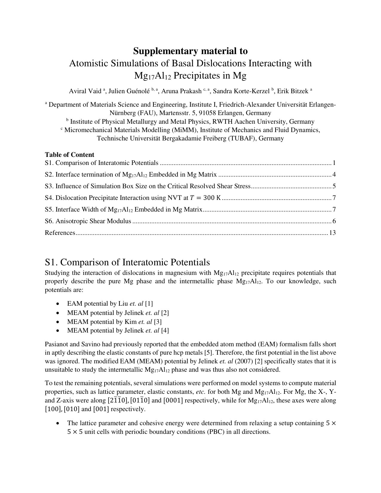 Figure 1
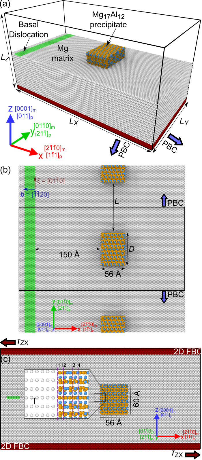 Figure 1
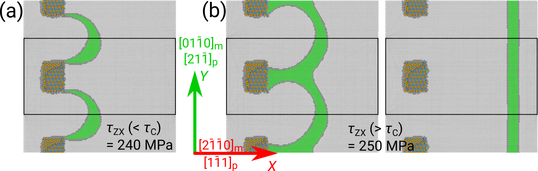 Figure 2
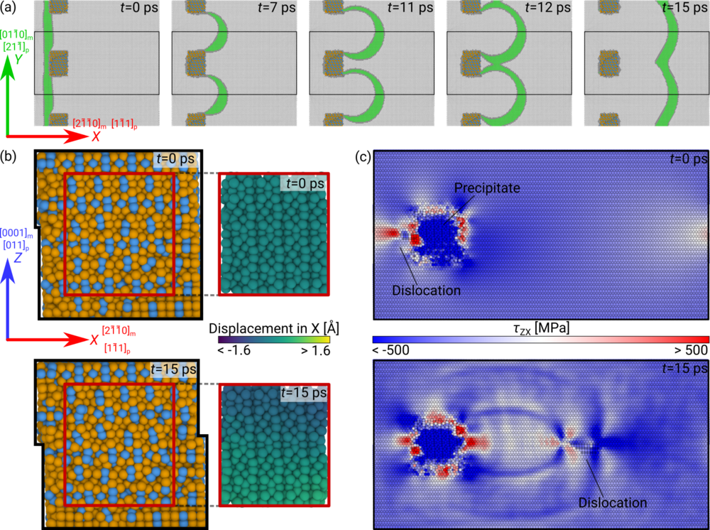 Figure 3
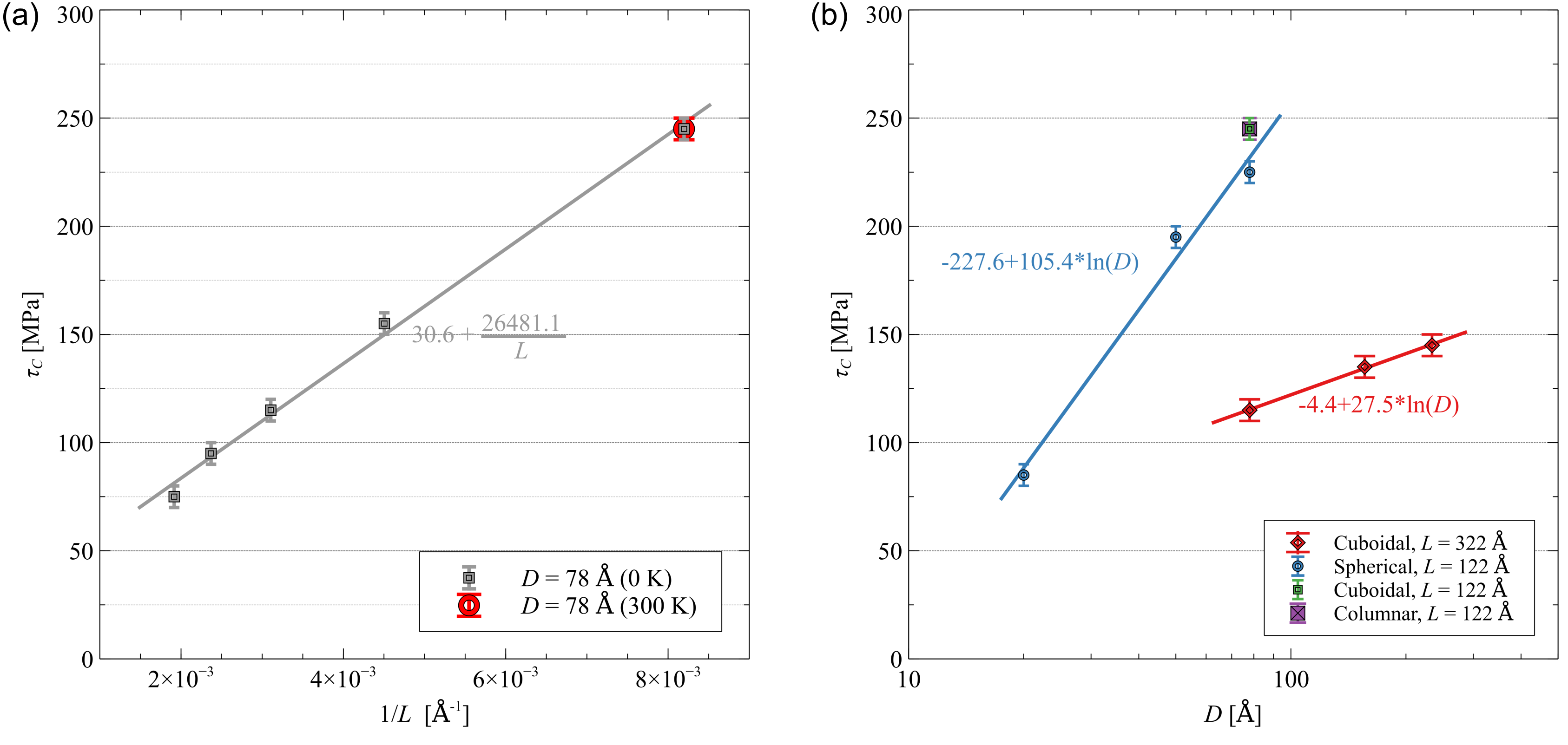 Figure 4
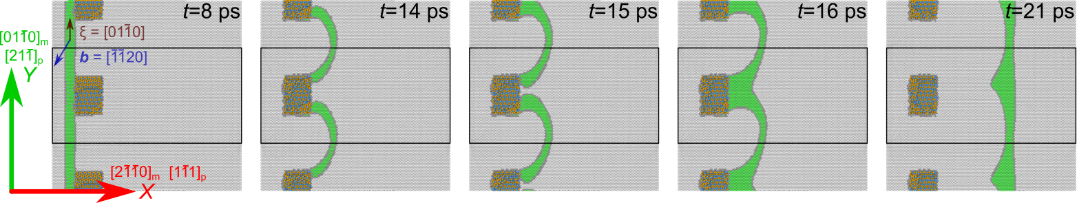 Figure 5
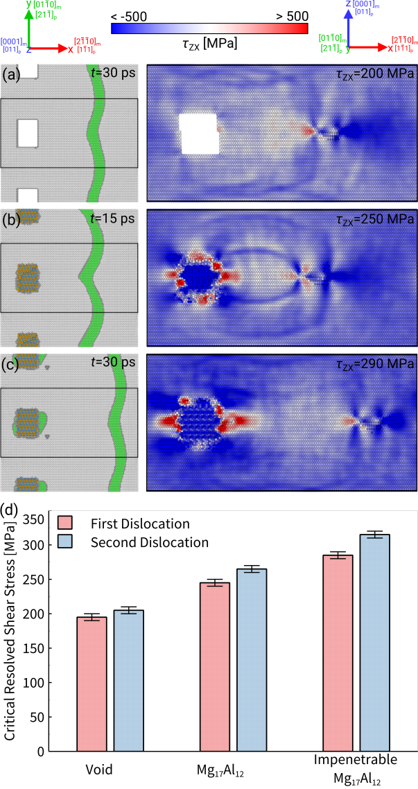 Figure 6
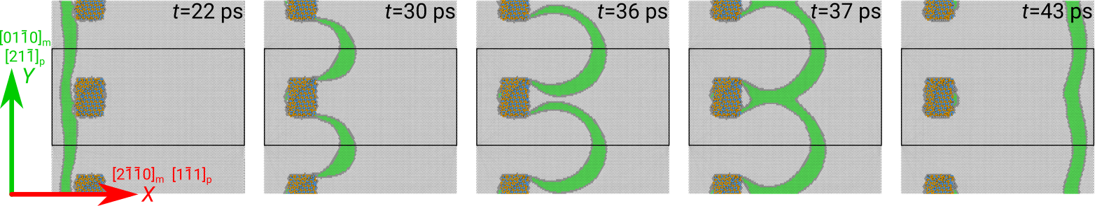 Figure 7
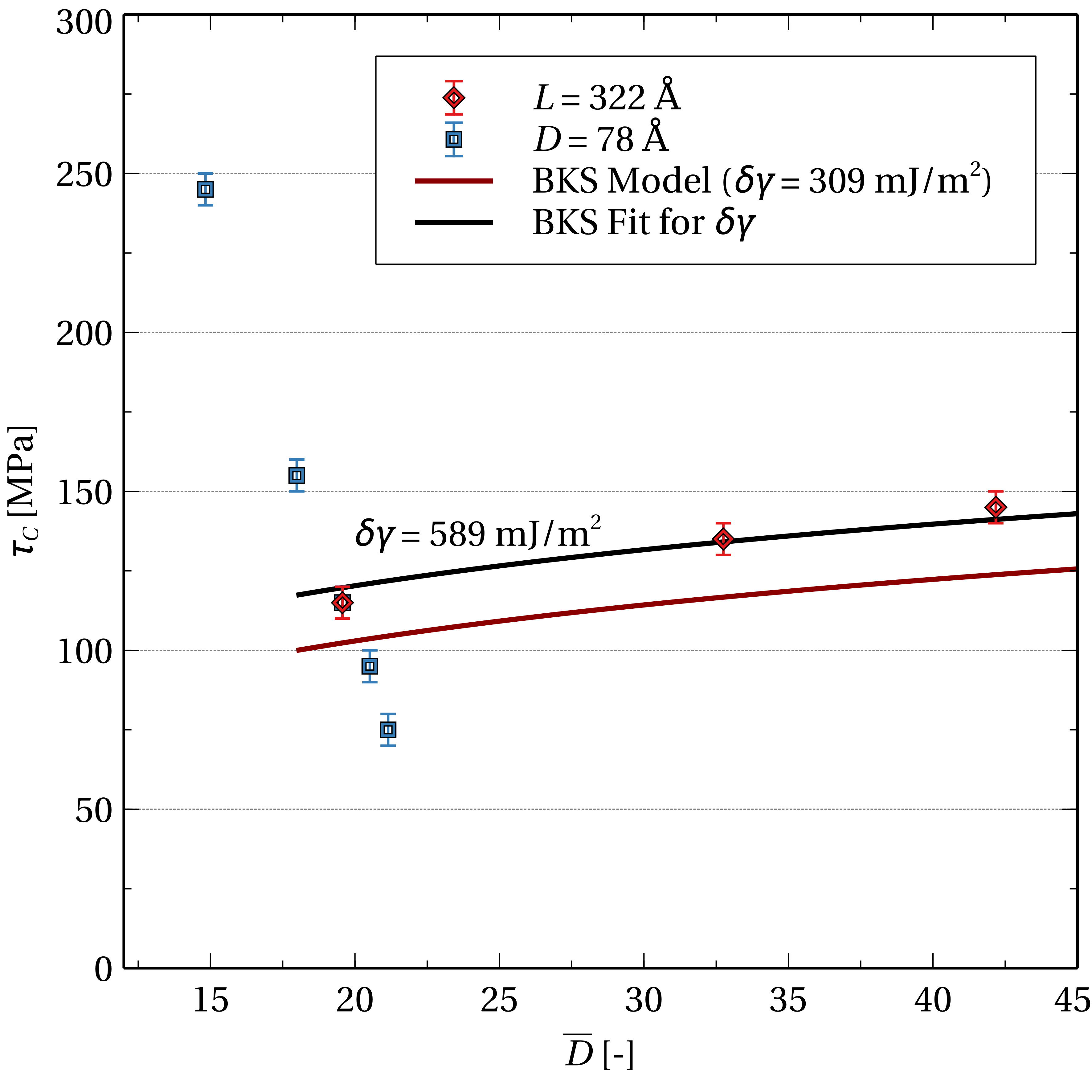 Figure 8
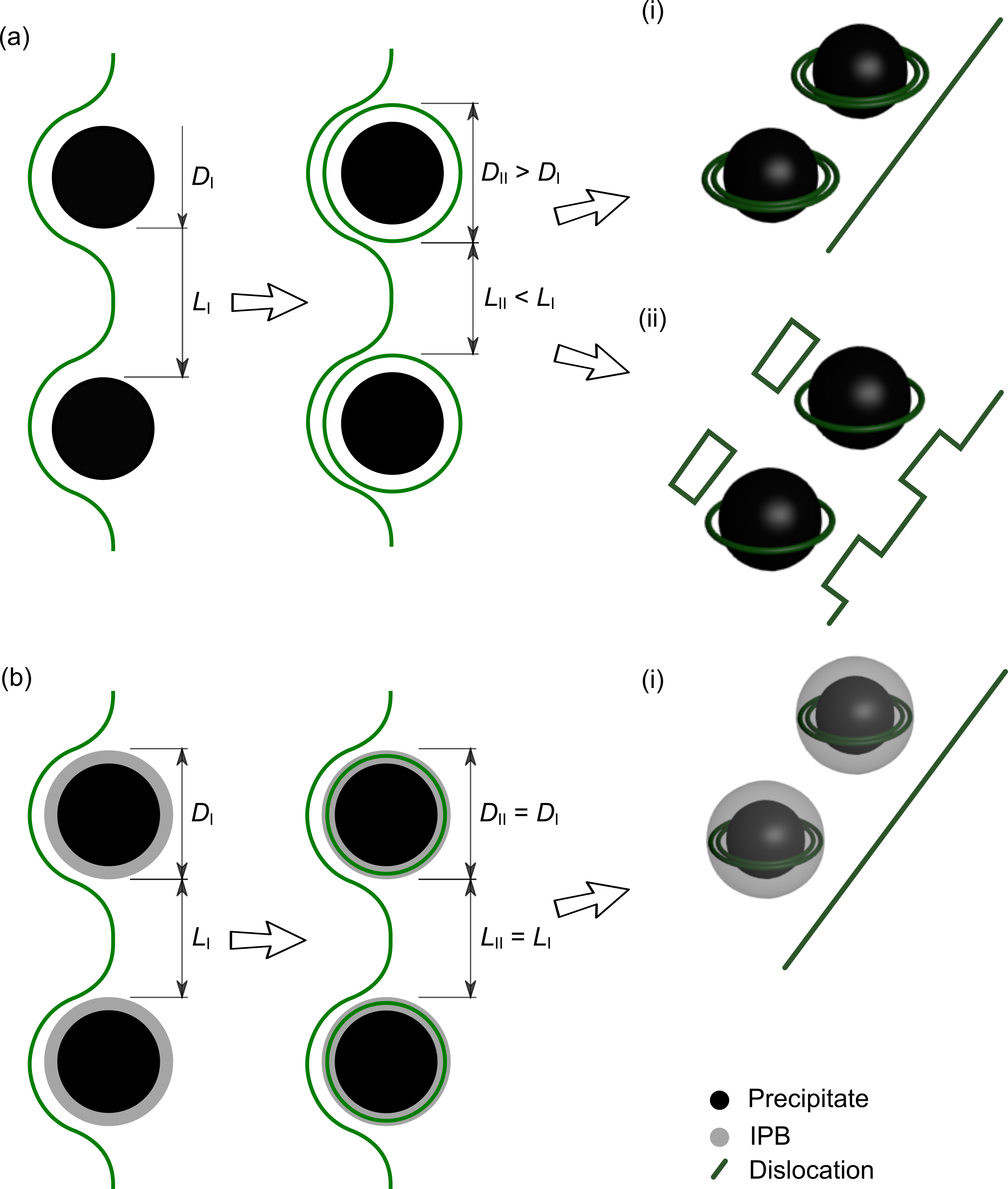 Figure 9
| Parameters | Parameter Range | Default setup |
| Precipitate spacing | ||
| – (Å) | 122, 222, 322, 422, 522 | 122 |
| Precipitate geometry | ||
| – shape | cuboidal, column, sphere | cuboidal |
| – width, cuboidal (Å) | 78, 156, 234 | 78 |
| – diameter, sphere (Å) | 20, 50, 78 | – |
| Matrix-precipitate interface | ||
| – orientation relationship (OR) | Burgers OR(, ), | |
| \hkl[1-11]p \hkl[2-1-10]m and \hkl(21-1)p \hkl(0001)m (, ), | Burgers OR | |
| \hkl[011]p \hkl[2-1-10]m and \hkl(-11-1)p \hkl(0001)m (, ) | ||
| – slip plane alignment | \hkl(0001)m/\hkl(011)p, \hkl(0001)m/\hkl(033)p | \hkl(0001)m/\hkl(011)p |
| – termination (type) | I1, I2, I3, I4 | I1 |
| Dislocation | ||
| – character | edge (b = \hkl[-2110], = \hkl[01-10]), | edge |
| mixed 30º(b = \hkl[-1-120], = \hkl[01-10]) | ||
| Obstacle | ||
| – type | void, precipitate, impenetrable precipitate | precipitate |
| Varied parameter | Parameter value | [MPa] |
| Precipitate spacing (Å) | 122 | |
| 222 | ||
| 322 | ||
| 422 | ||
| 522 | ||
| Precipitate geometry | ||
| – Cuboidal (width in Å) | 78 | |
| 156 | ||
| 234 | ||
| – Spherical (diameter in Å) | 20 | |
| 50 | ||
| 78 | ||
| – Columnar (width in Å) | 78 | |
| Matrix-precipitate interface | ||
| – orientation relationship | Burgers OR | |
| \hkl[1-11]p \hkl[2-1-10]m, \hkl(21-1)p \hkl(0001)m | ||
| \hkl[011]p \hkl[2-1-10]m, \hkl(-11-1)p \hkl(0001)m | ||
| – slip plane alignment | \hkl(0001)m/\hkl(011)p | |
| \hkl(0001)m/\hkl(033)p | ||
| – termination (type) | I1 or I3 | |
| I2 or I4 | ||
| Dislocation character | ||
| – edge | \hkl(0001)m/\hkl(011)p | |
| \hkl(0001)m/\hkl(033)p | ||
| – 30º | \hkl(0001)m/\hkl(011)p | |
| \hkl(0001)m/\hkl(033)p | ||
| Obstacle type | void | |
| precipitate | ||
| frozen atoms |
Peer Reviews
No public reviews on file for this paper yet. If you reviewed it on a platform where reviews are public (OpenReview, ICLR, NeurIPS, ICML), you can paste yours below so the community can read it here.
Videos
No videos yet. Explain this paper in a talk, walkthrough, or lecture? Add one.
Atomistic Simulations of Basal Dislocations Interacting with
Mg17Al12 Precipitates in Mg
Aviral Vaid
Julien Guénolé
Aruna Prakash
Sandra Korte-Kerzel
Erik Bitzek
Department of Materials Science and Engineering, Institute I, Friedrich-Alexander-Universität Erlangen-Nürnberg (FAU),
Martensstr. 5, 91058 Erlangen, Germany
Institute of Physical Metallurgy and Metal Physics, RWTH Aachen University, Germany
Micromechanical Materials Modelling (MiMM), Institute of Mechanics and Fluid Dynamics,
Technische Universität Bergakademie Freiberg (TUBAF), Germany
Abstract
The mechanical properties of Mg-Al alloys are greatly influenced by the complex intermetallic phase Mg17Al12, which is the most dominant precipitate found in this alloy system. The interaction of basal edge and 30º dislocations with Mg17Al12 precipitates is studied by molecular dynamics and statics simulations, varying the inter-precipitate spacing (), and size (), shape and orientation of the precipitates. The critical resolved shear stress to pass an array of precipitates follows the usual proportionality. In all cases but the smallest precipitate, the dislocations pass the obstacles by depositing dislocation segments in the disordered interphase boundary rather than shearing the precipitate or leaving Orowan loops in the matrix around the precipitate. An absorbed dislocation increases the stress necessary for a second dislocation to pass the precipitate also by absorbing dislocation segments into the boundary. Replacing the precipitate with a void of identical size and shape decreases the critical passing stress and work hardening contribution while an artificially impenetrable Mg17Al12 precipitate increases both. These insights will help improve mesoscale models of hardening by incoherent particles.
keywords:
Precipitation Strengthening, Atomistic Simulations, Molecular Dynamics/Statics, Magnesium Alloys, Mg17Al12
††journal: Materialia
1 Introduction
Precipitation strengthening is known to enhance yield and flow stress of metallic alloys by the presence of second-phase particles distributed in a homogenous matrix that impede the motion of dislocations [1]. Various factors are known to influence the strengthening behavior in metallic alloys such as the size, shape, number and distribution of precipitates, the crystallographic alignment between the phases, the interfacial energy and the stacking fault and dislocation energies within the precipitates [2, 3, 4, 5, 6, 7, 8, 9, 10].
This strengthening effect is exploited in many engineering alloys, including magnesium. Mg alloys have recently attracted significant interest due to their low density, high specific strength, and good recyclability [11, 12, 13, 14]. They are of interest as structural materials for the automotive and aeronautical industries where a strong reduction in components’ weight lowers fuel consumption and gas emissions [15]. Understanding the plastic deformation mechanism in such precipitation-strengthened alloys is of prime importance for improving the modeling of light-weight materials and for developing novel alloys with improved properties. The main alloying element in most Mg alloys is aluminum, which leads to the formation of several intermetallic phases, the most common being Mg17Al12 [16, 17, 18, 11]. Mg17Al12, therefore, plays a key role in increasing the yield strength of Mg-Al alloys mainly by hindering the easy glide of dislocations on the basal plane of the Mg-matrix.
The interactions between dislocations and discrete obstacles have been studied since the early days of dislocation theory using experimental techniques [19, 20, 21, 22, 23], and linear elasticity [24, 25, 26] as well as, more recently, dislocation dynamics modeling [5, 27, 28, 29, 30, 10] and atomistic simulations [4, 2, 7, 31, 32, 8, 33, 34, 35, 9, 36]. A detailed review of atomic-scale modeling of dislocation-obstacle interactions can be found in [3]. Most simulation studies on dislocation-obstacle interactions have so far been performed on fcc and bcc metals. Here, typical obstacles include voids or vacancy clusters and precipitates, either as artificially impenetrable obstacles or by considering realistic material-specific alloy systems. Currently, only comparatively few simulation studies exist in the literature that specifically address dislocation-obstacle interactions in hcp metals, like the recent molecular static simulations by Groh [37] who studied basal edge dislocations in Mg interacting with spherical obstacles generated by artificially immobilizing Mg atoms. Even fewer atomistic simulation studies exist on dislocations in simple hcp, fcc or bcc metals interacting with complex intermetallic precipitates [38, 39, 40].
Regarding the Mg-Al system of interest in this study, most of the recent work was performed in the group of Horstemeyer[40, 41, 42]. However, the properties of the complex intermetallic phase Mg17Al12 depend crucially on the used interatomic potential. For example, the modified embedded atom model (MEAM) potential by Jelinek et al. [43] used by Liao et al. [40, 41, 42] gives a negative shear modulus and a positive enthalpy of formation for the stable Mg17Al12 phase. More recently, Moitra and Llorca [44] used an embedded atom model (EAM) potential instead of an MEAM potential for the Mg-Al system. However, this potential has a problem with the matrix phase, as EAM potentials, in general, inaccurately represent the elastic constants of hcp materials [45]. For a detailed analysis and comparison of Mg-Al potentials the reader is referred to the supplementary material section S1.
In the following, we present a detailed qualitative as well as quantitative atomistic simulation study of edge and mixed basal dislocations in Mg interacting with different types of obstacles, with the focus on Mg17Al12 precipitates of varying size, shape and spacing.
2 Methodology
The atomistic simulations presented in this work were performed with the classical molecular dynamics code LAMMPS [46] (version 16 Mar 2018). Atomic interactions were modeled by the MEAM potential of Kim et al. [47], which was found to best represent an atomistic system consisting of both Mg and Mg17Al12 (see supplementary material section S1 for a comparison study between different potentials).
2.1 Sample Setup
A typical simulation setup used in the present work is shown in figure 1. It consists of an hcp-Mg matrix with the basal \hkl(0001) plane-normal parallel to the Z-axis, a dislocation with line direction = \hkl[01-10] parallel to the Y-axis and a precipitate. Periodic boundary conditions (PBC) were used along the dislocation line direction and the direction of dislocation motion, i.e., along the X and Y directions. This setup corresponds therefore to an array of infinite dislocations that interacts with a periodic array of obstacles, as illustrated in fig. 1(b), and allows the study of multiple interactions of the dislocation with the obstacles. Atoms in the top and bottom boundary layers were constricted to move only within the Z-plane (2D dynamic boundary layers).
Edge and 30º dislocations with Burgers vectors b = \nicefrac{{a_{0}}}{{3}} \hkl¡-2110¿ were introduced following the method detailed in [48] and [2], where is the lattice constant of Mg at . The precipitates were inserted approx. 150 Å in front of the dislocation (see fig. 1(b)) by removing the matrix atoms and filling the resulting void with Mg and Al atoms arranged in the bcc-like crystal structure of the Mg17Al12 phase (space group ) [16, 49]. The relative orientation of the Mg matrix and the Mg17Al12 precipitate follows the experimentally-observed Burgers orientation relationship (OR) [17]: \hkl[1-11]p \hkl[2-1-10]m and \hkl(011)p \hkl(0001)m. The glide plane of the dislocations were aligned with a \hkl011 plane in Mg17Al12, which is assumed to be the natural glide planes of the phase [50, 51], thus presumably allowing for easy slip transmission into the precipitate.
In the present work, we varied the inter-precipitate spacing, precipitate geometry, matrix-precipitate interface, dislocation character and obstacle type (Mg17Al12 precipitate, Mg17Al12 precipitate with artificially frozen atoms and a void). Due to the complex crystallography of the precipitate, we prepared various interfaces that follow the Burgers OR while modifying the interface termination at the precipitate (see inset fig. 1(c), supplementary material section S2). The same cuboidal precipitate was additionally rotated by 90º anti-clockwise along X-axis and along Y-axis relative to the position shown in fig. 1(b) to create setups with different interfaces. The variations of the simulation setup are summarized in tab. 1. Most simulations were performed using the values in the last column (tab. 1) and the setup is hereto referred as default setup. To study the influence of each parameter, only one characteristic was modified at a time relative to the default setup while keeping the others constant. Care was taken to minimize the influence of box size and spurious image forces on the quantitative evaluation of CRSS in our simulations following Szajewski et al. [52] (see supplementary material section S3)
2.2 Atomistic Simulations
The created samples were relaxed by first using a local relaxation [53] followed by a full relaxation using an optimized implementation [54] of the FIRE [55] algorithm to reach the equilibrium state. The samples were considered sufficiently relaxed when the force norm, i.e., the norm of the 3N-dimensional force vector, fell below a threshold value of eV/Å.
The critical resolved shear stress (CRSS) required for a dislocation to overcome the precipitates was computed using a series of molecular statics (MS) simulations. Each setup was pre-sheared along in direction of the Burgers vector according to the value of the desired resolved shear stress, using the corresponding elastic constants of the Mg matrix (see supplementary material section S4) Forces corresponding to the desired shear stress were applied to the atoms in the top and bottom layers parallel to the glide plane (2D FBC, see fig 1). This leads to a symmetric shear state on the slip plane situated in the middle of the setup. The CRSS required for a dislocation to overcome a precipitates was determined by bracketing. The default setup was also unloaded from a relaxed configuration by removing any externally applied shear stresses and allowing the system to reach an energy minimized state.
The dynamics of the dislocation-obstacle interactions were furthermore studied using molecular dynamics (MD) simulations, using either the NVE ensemble with an initial temperature of 0\text{,}\mathrm{K} or in the NVT ensemble at $T=$300\text{\,}\mathrm{K} (default setup with edge or mixed 30ºdislocation only). For the simulations, the sample was expanded according to the lattice constant of the Mg matrix at and subsequently equilibrated at for while keeping the setup stress-free using Nosé -Hoover thermostat and barostat [56, 57, 58]. The time step for all the MD simulations was set to 1.0\text{,}\mathrm{f}\mathrm{s}$$.
The lower bound of the CRSS corresponds to the highest applied shear stress for which a static simulation (following the above described procedure and minimization criterion) resulted in a stable equilibrium configuration with a pinned dislocation. The upper bound of the CRSS corresponds to the lowest applied shear stress for which no stable equilibrium configuration could be found and the dislocation was no longer pinned. In the following, the CRSS is provided as the central value between the upper and the lower bound while the error gives the interval between these bounds.
2.3 Visualization and Analysis
The Open Visualization Tool (OVITO) [59] was used to visualize and analyze the atomistic configurations. Common neighbor analysis (CNA) [60, 61] was used to identify defects in the Mg matrix. Displacement vector analysis was used to compute the relative displacement between two atomic configurations. Atomic stresses were calculated based on the virial formulation [62] and the atomic Voronoi volume [63, 64]. Stresses represented in the current work have been averaged over the nearest neighbors. Atoms within of the IPB were classified as ”other” by the CNA algorithm. Although this classification is often associated to amorphous structures, it is important to point out that the present inter-phase boundary (IPB) structure is not amorphous but rather disordered (see section S5 in the supplementary material).
3 Results
3.1 First dislocation-precipitate interaction
Upon energy minimization, the dislocation in the default setup was attracted to the IPB and was found to be already at the precipitate, even when no stress was applied, see fig. S6 in the supplementary material. From this relaxed initial structure, the CRSS for a basal edge dislocation to overcome the precipitate in the default setup (122\text{,}\AA, $D=$78\text{\,}\AA) was determined to be 5\text{,}\mathrm{MPa}, *i.e.*, at $\tau_{\text{zx}}=$240\text{\,}\mathrm{MPa} minimization resulted in a relaxed pinned dislocation, see fig. 2, whereas at 250\text{,}\mathrm{MPa} the dislocation passed the precipitate array. The relaxed configuration at $\tau(<\tau_{C})=$240\text{\,}\mathrm{M}\mathrm{P}\mathrm{a}) was furthermore unloaded to 0 stress and a subsequent energy minimization was performed. The parts of the dislocations which were absorbed into the IPB remained in the IPB while the rest of the dislocation line assumed a straight shape, see fig. S9 in the supplementary material. In some setups (depending on dislocation line-length, dislocation character, precipitate shape), the dislocation was not at the interface upon initial energy minimization with 0\text{,}\mathrm{M}\mathrm{P}\mathrm{a}. These configurations were additionally relaxed with a nominal initial applied stress $\tau=$10\text{\,}\mathrm{M}\mathrm{P}\mathrm{a} such that the dislocation was at the matrix-precipitate interface. The CRSS, , for all simulated configurations in tab. 1 are reported in tab. 2.
Snapshots of the interaction of an initially straight edge dislocation at 250\text{,}\mathrm{MPa} with the precipitates in the *default setup* are shown in fig. [3](#S3.F3)(a) (NVE, $T_{0}=0\text{K}$). At $t=$0\text{\,}\mathrm{ps}, the dislocation started at the leftmost matrix-precipitate interface. The dislocation moved further to the right and at 7\text{,}\mathrm{ps} bowed out between the precipitates. At $t=$11\text{\,}\mathrm{ps}, the dislocation reached a maximum bow-out state. The dislocation arms on both sides of the precipitate attracted each other and annihilated at 12\text{,}\mathrm{ps}, after which the dislocation depinned from the precipitate ($t=$15\text{\,}\mathrm{ps}). Using the common neighbor analysis, no dislocation loops were visible in the matrix around the precipitate, both in the static and in the dynamic simulations at different temperatures.
Figure 4(a) shows the CRSS for different inter-precipitate spacings, . Increasing the inter-precipitate distance resulted in a smaller value of .
To study the effect of precipitate shape, spherical, rectangle-columnar (spanning the height of the simulation box) and cuboidal (as used for the default setup) geometries were used in the simulations. Note that changing the precipitate shape also implies that the matrix-precipitate interfaces were crystallographically different. The CRSS for a spherical precipitate was lower than for cuboidal or columnar precipitates (see fig. 4(b), 122\text{,}\AA$$). The mechanism by which the dislocation passes the precipitates was the same for all precipitates, except for the spherical one with a diameter of 20 Å, which was cut by the incoming dislocation.
Figure 4(b) also shows the effect of varying precipitate size (width for cuboidal, diameter for spherical precipitates) on . Instead of the default value of 122\text{,}\AA a larger value of $L=$322\text{\,}\AA was constantly used for a cuboidal precipitate. As can be seen in fig. 4(b) the CRSS showed a logarithmical dependence with the precipitate size.
To study the influence of the matrix-precipitate interface structure on the dislocation-precipitate interaction, the interface was modified in three ways: (1) by rotating the precipitate and thus, changing the orientation relationship between the matrix and the precipitate, (see tab. 2) (2) by changing the slip plane of the matrix dislocation so that it aligns with the \hkl330 plane of the Mg17Al12 precipitate instead of the \hkl110 plane, and (3) by changing the termination plane of the precipitate at the matrix-precipitate interface (see supplementary material section S2). Changing the OR between the matrix and precipitate may change the effective inter-precipitate distance and the precipitate width, leading to a lower CRSS. Changing the relative alignment of the slip plane of the matrix dislocation with respect to the precipitate did not influence the CRSS. Changing the termination plane of the precipitate at the matrix-precipitate resulted in only slight variations in as can be seen in tab. 2.
To study the influence of the character of the dislocation on its interaction with the precipitate, a 30º dislocation was introduced in the matrix instead of the default edge dislocation. Forces equivalent to a shear stress greater than were applied to the system along the direction of the Burgers vector. Figure 5 shows the interaction of a 30º dislocation with Mg17Al12 precipitates in an NVE simulation at . The shown stages of dislocation-precipitate interactions are the same as in fig. 3(a), however, as the dislocation did not approach the precipitate during energy minimization, the times in both figures are not identical. At 8\text{,}\mathrm{ps}, the dislocation arrived at the matrix-precipitate interface, and continued to move along the sides of the precipitates (see $t=$14\text{\,}\mathrm{ps}). At 15\text{,}\mathrm{ps}, the dislocation reached its maximum bow out state. Before overcoming the precipitate, the dislocation arms interacted and annihilated each other ($t=$16\text{\,}\mathrm{ps}) before the dislocation finally detached (21\text{,}\mathrm{ps}$$). In contrast to the edge dislocation, fig. 3(a), the maximum bow-out configuration of the 30º dislocation was asymmetric, but the overall mechanism of interaction was similar to the edge dislocation case. The CRSS for the 30º dislocation was about 10% larger than that for an edge dislocation (see tab. 2). Similar to the edge dislocation case, changing the alignment of the slip plane did not affect the CRSS.
We performed additional simulations of selected configurations at and found no change of interaction mechanism for either edge or 30º dislocations (see supplementary material section S6), and the CRSS of the default setup was - within the bracketing interval - identical to the CRSS at (see figure 4).
Two extreme cases of obstacles were studied in addition to the default Mg17Al12 precipitate: an impenetrable Mg17Al12 precipitate achieved by fixing the corresponding atomic positions, and a void, both of the same shape and size as the default precipitate. Figure 6 shows snapshots from the corresponding MD simulations (NVE, 0\text{,}\mathrm{K}$$) when the edge dislocation has passed the obstacle. In the case of the void, fig. 6(a), the dislocation was attracted to the void. The part of the dislocation touching the void disappeared at the free surface leaving a step, while the remaining dislocation moved along the void, bowed out with the side arms annihilating and creating a step at the back surface of the void in the process. With the fixed Mg17Al12 precipitate (fig. 6(c)), the dislocation overcame the precipitate by Orowan looping, similar to the already addressed case of the default Mg17Al12 precipitate fig. 6(b) In this case, a dislocation loop in the matrix was clearly detected by the CNA algorithm. The corresponding stress states after obstacle passage are also shown on the right of fig. 6.
The CRSS to pass the void was 20% lower than for the Mg17Al12 precipitate of identical size. The impenetrable Mg17Al12 precipitate, on the other hand, required an about 15% higher resolved shear stress than the Mg17Al12 precipitate with mobile atoms, see fig. 6(d).
3.2 Second dislocation-precipitate interaction
After having overcome the obstacle, the dislocation can pass through the PBC and interact a second time with the same obstacle. Quasi-static simulations were performed iteratively by increasing the applied shear stress by until the dislocation overcame the obstacle during energy minimization, using the previous relaxed configuration. The inertial effects from the pseudo-dynamics of FIRE [2, 55] were avoided as the starting configuration was relaxed with the dislocation next to the precipitate. The CRSS for the second interaction are shown in fig. 6(d). While in case of the void, the CRSS for the second edge dislocation passing was within the error margin of the CRSS for the first passage, the CRSS for the second dislocation-precipitate interaction in the case of the Mg17Al12 precipitate was about 8% higher than for the first dislocation passing. The increase in resolved shear stress necessary to pass the impenetrable Mg17Al12 precipitate a second time was 10% higher — slightly more pronounced than for the Mg17Al12 precipitate with mobile atoms.
Snapshots from the MD simulation of the second dislocation interaction with the precipitate (NVE, 0\text{,}\mathrm{K}, $\tau=$270\text{\,}\mathrm{MPa}) are shown in fig. 7. Here, the starting configuration was relaxed at 0\text{,}\mathrm{MPa}$$ and the dislocation was next to the precipitate. The applied shear stress was larger than the CRSS; therefore the dislocation overcame the precipitate and re-interacted with it. In this case, the inertial effects during the second dislocation interaction with the precipitate cannot be neglected. As can be seen from fig. 7, the mechanism of interaction is the same as for the first passage, fig. 3. Small dislocation segments remaining in front and in the back of the precipitate can be identified, see fig. 7, which were subsequently absorbed.
The relaxed interface structure before and after absorption of the first and second dislocation are shown in fig. S5 in the supplementary material. The step at the interface where the edge dislocation was absorbed is clearly visible and increasing with the absorbed dislocation contents, while remaining disordered. Any visible changes in the IPB structure were confined to the region where the dislocation was absorbed (see fig. S5 in the supplementary material).
4 Discussion
The absence of any visible dislocation loop around a precipitate after dislocation passage and the presence of a step at the precipitate-matrix interface is commonly taken as an indication that the dislocation sheared the precipitate. Indeed, Moitra and LLorca [44] used these criteria to determine that the to Mg17Al12 disc-shaped precipitates in Burgers orientation relationship, which they simulated, were sheared by a basal edge dislocation inserted in the Mg Matrix. Liao et al.[40], on the other hand, found that for a Mg17Al12 precipitate in the same orientation relationship, the edge dislocation only caused elastic deformation of the precipitate. These studies were, however, performed with different potentials than in the present simulations, that have certain deficiencies when coming to model the Mg-Mg17Al12 system, see section S1 of the supplementary material.
Figure 3(b) shows clear steps at the precipitate after dislocation passage. However, when only considering the precipitate interior, the displacement field shows no plastic deformation after the dislocation passed the precipitate, see the insets in fig. 3(b). Additionally, analysis of the stress field around the precipitate, fig. 3(c), reveals at t=$$15\text{\,}\mathrm{p}\mathrm{s} a remaining stress signature in front and in the back of the precipitate similar to the one of the dislocation in front of the precipitate (t=$$0\text{\,}\mathrm{p}\mathrm{s}). These are clear indications that instead of leaving an Orowan loop in the matrix around the precipitate, the dislocation was absorbed in the Mg/Mg17Al12 interface. The absence of Orowan loops and the presence of steps at the precipitate-matrix interface can, therefore, not be used to infer that precipitates were sheared.
It is well known that interphase boundaries (IPB), similar to grain boundaries, can act as sinks for dislocations [65, 66, 67, 68, 69] We observed that dislocation absorption took place in all of our simulations with Mg17Al12 precipitates, except the smallest one, independent of the details on how exactly the matrix-precipitate interfaces were constructed (different terminations, precipitate shapes and orientations, see tab. 1), dislocation character or the simulation temperature. This fact points to dislocation absorption in the IPB as generic feature for basal dislocations in Mg interacting with Mg17Al12 precipitates. Liao et al.[40], however, found for a 3 nm Mg17Al12 precipitate a different interaction mechanism, which they interpreted as cross-slip of their basal edge dislocation. Their observed resulting dislocation configuration after the edge dislocation passed the precipitate with two super-jogs could also be explained by the absorption by the dislocation of vacancies from an excess free volume at the interface. In this case, the edge dislocation would have been effectively climbing over the precipitate. The way the IPBs are created in the atomistic simulations can therefore have important consequences on the dislocation precipitate interaction mechanisms.
High-resolution transmission electron microscopy (HR-TEM) analysis of Mg-Mg17Al12 interfaces shows local distortions at the interphase boundary [70, 71]. Although, these images may not directly resolve the local structure, the loss of contrast from distinct atomic columns indicates that the interface is not perfectly coherent despite the orientation relationship being maintained between the two phases. This observation agrees with the disordered IPB structure in our simulations (see supplementary material section S5) An IPB with excess free volume (see also fig. S4 in the supplementary material) facilitates the absorption of dislocations. The IPB thickness of approx. surrounding the particle in our simulations also explains why the smallest spherical precipitate was sheared in our simulations, as nearly most of its atoms were part of the IPB.
In order for dislocations to be absorbed in the Mg/Mg17Al12 IPB, the image force on the dislocation caused by the different elastic constants of the precipitate and the matrix [72] has to be either negligible or attractive. A repulsive image force as in the case of the fixed Mg17Al12 would cause a certain stand-off distance of the dislocation, resulting in a visible Orowan loop as can be seen in fig. 6(c). Using the shear modulus in slip plane and slip direction with the values for the used potential shows that Mg17.2\text{,}\mathrm{G}\mathrm{P}\mathrm{a}Mg17Al1217.6\text{,}\mathrm{G}\mathrm{P}\mathrm{a}$$ (see supplementary material section S4). Comparing the elastic constants from MEAM potential with DFT and experiments for both phases, no differences are expected (supplementary material section S1).
From the fact that the precipitate in the default setup is not sheared by a second dislocation, one can deduce a lower bound for the CRSS to shear the Mg17Al12 by assuming a pile-up of dislocations at an applied shear stress of 250\text{,}\mathrm{M}\mathrm{P}\mathrm{a}, fig. [6](#S3.F6)(d), to $\tau_{\text{c,min}}=n\tau=$500\text{\,}\mathrm{M}\mathrm{P}\mathrm{a}. This is consistent with the higher stress required to move dislocations in the complex intermetallic phase Mg17Al12 compared with the pure metallic Mg matrix. At room temperature, the hardness of Mg17Al12 has been measured as and in micro- and nano-hardness measurements, respectively [73, 74]. In contrast, the micro-hardness of pure magnesium has been measured to [75]. The much higher hardness of the intermetallic phase is also evidenced by its brittle behavior at room temperature, where fracture becomes dominant in macroscopic mechanical testing [76, 77, 78, 51]. This is consistent with the tetrahedral packing leading to corrugated crystallographic planes in Mg17Al12 and the correspondingly large perfect Burgers vector expected on these planes which lead to limited thermal activation of dislocation glide, as found in hardness measurements between room temperature and [73]. Although Xiao et al. [50] suggested a specific \hkl(110) slip plane and microcompression experiments have confirmed slip traces consistent with this type of plane [79], the actual Burgers vector, including that of any partial dislocations and the exact slip planes of Mg17Al12 have, however, not yet been unambiguously identified.
The critical resolved shear stress in dislocation - obstacle interactions can be significantly reduced by so called ’inertial overshooting’, particular at low temperatures and high dislocation velocities [55, 2]. As FIRE uses 0K pseudo-dynamics [55], similar inertial effects can in principle occur during minimization if the dislocations are initially far away from the obstacles. In the present study, however, no such inertial effects are expected as the dislocations were close to the precipitates when the CRSS was determined.
The critical resolved shear stress to unpin a dislocation from a periodic array of strong obstacles like voids or impenetrable particles has been shown to be dominated by the stress necessary to pull out the dislocation segments at the obstacle into a parallel dipole [80]. Bacon, Kocks and Scattergood [80] and Scattergood and Bacon [81] developed the following expression for by fitting their results obtained by computer simulations based on elasticity theory, which explicitly modeled the self-stress of a flexible dislocation:
[TABLE]
In this expression, which will henceforth be referred to as the BKS model, is the shear modulus in slip plane and slip direction, equals 1 for an initially pure edge dislocation and for a pure screw dislocation, where is Poisson’s ratio, is the magnitude of the Burgers vector and is the harmonic mean of the inter-obstacle spacing and the obstacle width : . The empirical constant models the energetic costs associated with the specific dislocation-obstacle interaction. In the case of a void, it describes the resisting force caused by creation of a surface step [81]:
[TABLE]
Here, is the energy of the newly created interface (in case of a void, equals , the energy of a free surface) and are the outer and inner cut-off radii in the calculation of dislocation energy (the factor is usually taken to be unity).
Figure 8 shows the values of determined from the simulations of an edge dislocation interacting with Mg17Al12 precipitates of various diameters and spacing as function of . Using the BKS model with 17.2\text{,}\mathrm{GPa}, $b=$3.204\text{\,}\AA and an estimate for the interface step energy 309\text{,}\mathrm{mJ}\text{,}{\mathrm{m}}^{-2} calculated for a \hkl(011)*p* $\parallel$\hkl(0001)*m* interface (following the same methodology as in [[82](#bib.bib82)]) results in too low values for $\tau_{c}$ compared to the simulations. Fitting the BKS model to the data results in $\delta\gamma=$589\text{\,}\mathrm{mJ}\text{\,}{\mathrm{m}}^{-2}, i.e., the energy of the absorbed dislocation in the IPB is much larger than the energy created by interfacial steps of width .
The energy of the absorbed dislocation in the IPB, modeled by in eq. 1, can be influenced by the temperature. In the simulations, no effect of temperature was observed on the CRSS at 300K (see figure 4) for 122\text{,}\AA78\text{,}\AA. On experimental time scales the dislocation core might spread and dissolve within the IPB, which could lead to some temperature dependence of the CRSS. The main contribution to the obstacle strength is however the elastic energy due to the dislocation dipole configuration, which should not be strongly dependent on temperature.
Interestingly, the BKS model predicts a larger for voids than for the Orowan process ( [80, 81]. Our simulations with 78\text{,}\AA and $L=$122\text{\,}\AA (), however, show that the void has 0.8 times smaller than an Mg17Al12 precipitate with identical and , see fig. 6(d). This points to the importance of the specific details of the precipitate and the IPB, which were not accounted for in the derivation of the BKS model [80] and can become particularly important for small .
This becomes particularly evident when considering the fixed Mg17Al12 precipitate, which has a 1.2 times higher than the Mg17Al12 precipitate. Here, the infinitely stiff obstacle leads to high image forces and subsequently a higher energy of the Orowan loop, which are not accounted for in the original BKS model with non-interacting obstacles of identical elastic properties as the matrix [80]. Their model of a flexible dislocation, however, captures the importance of the Burgers vector orientation relative to the obstacle row and predicts a higher for mixed dislocations as compared to a pure edge dislocation, in agreement with our results for a 30º dislocation, see tab. 2.
The BKS model does not consider the interaction of multiple dislocations with the same obstacle, i.e., the change of upon repeated bowing or cutting, which would reflect as hardening or softening during ongoing plastic deformation. In agreement with the simulation results on voids, fig. 6(d), no significant change in is expected for voids that are not completely sheared apart, as the increase in surface energy is not expected to change much with the step size. For the Orowan process, however, the Orowan loops left around the obstacle by previously interacting dislocations affect subsequent dislocations. I.e., the work hardening rate for metals and alloys containing unshearable particles is different from the same material without particles or with shearable precipitates [83, 25, 29]. The Orowan loops contribute to short- and long-range interactions with other dislocations [83]. The short-range interaction reduces the effective inter-particle distance and has a significant strengthening effect. This so-called source-shortening effect [25] was recently studied by dislocation dynamics simulations, where Queyreau et al.[29] could show that this effect of the accumulated Orowan loops can indeed be modeled by the classical approach of assuming an increased effective particle diameter and correspondingly a smaller in Eq. 1 [84], as illustrated in fig. 9(a).
The dislocation absorbed in the IPB clearly affects the second dislocation and leads to an increase in for the following dislocation, see figs.6(d) and 7. However, due to the absorption in the IPB, the effective particle diameter will not be the same as in the case of an Orowan loop in the matrix, even for otherwise identical particles. Furthermore, the line energy and stress field of dislocations can change upon absorption [86, 69, 68, 87], see also the stress fields in figs. 6(b) vs. 6(c). The contribution to work hardening by precipitates with absorbing interfaces is therefore expected to be different than for particles with interfaces that cannot absorb dislocations, even if other particle properties remain identical. Changes of dislocation properties in interfaces were first considered in the case of diffusive processes [88, 89, 86], where it helped to explain the creep behavior of oxide-dispersion strengthened (ODS) superalloys. The recent observations of dislocation-precipitate interactions by Huang et al.[87], however, suggest that diffusion-less interfacial dislocation relaxation processes can lower the line energy of dislocations absorbed in an IPB.
A further consequence of dislocations being absorbed in particle interfaces is that in contrast to Orowan loops in the matrix, they cannot take part in cross-slip processes. The combined cross-slip, Orowan mechanisms as suggested by Hirsch [20, 19], see also fig. 9(a)(ii), can therefore not take place. Figure 9 summarizes the different mechanisms possible in the case of Orowan looping in the matrix and dislocation absorption into the IPB.
In the present simulations, only dislocations in Mg interacting with Mg17Al12precipitates were shown to be absorbed into the IPB. However, the recent in-situ TEM indentation experiments on Mg-Nd alloys by Huang et al.[87] showed dislocation absorption at the interface of precipitates of the DO3 structure. Dislocation absorption into precipitate IPBs might therefore be more common for incoherent particles. The implications, like changes in dislocation energy and stress field, and unavailability of dislocations for cross-slip processes, are, however, to our knowledge not yet included in mesoscale models of particle hardening.
5 Summary
Molecular statics and dynamics simulations were performed on basal edge and 30ºdislocations in Mg interacting with an array of Mg17Al12 precipitates to determine the critical stress for obstacle passing and study the mechanisms of dislocation-precipitate interactions. Independent of temperature (up to ), precipitate diameter (20\text{\,}\AA$<D<$235\text{\,}\AA), precipitate shape, precipitate orientation, precipitate spacing, dislocation type, the relative alignment of slip planes in matrix and precipitate, and the preparation of the matrix-precipitate interface, the dislocations leave no visible Orowan loop in the matrix around the precipitate. Although a step is visible at the matrix-precipitate interphase boundary, the precipitate is not sheared, but the dislocation forming the Orowan loop is absorbed into the disordered boundary. As expected for Orowan looping, the critical resolved shear stress to pass the precipitates is not significantly influenced by changes in the matrix-precipitate orientation relationship or precipitate shape, as well as temperature, and is well-described by the Bacon, Kocks and Scattergood model. However, changing the type of obstacle by either removing all atoms belonging to the Mg17Al12precipitate and creating a void, or by fixing all their atomic positions and creating a stiff impenetrable obstacle changes the obstacle strength as well as the stress necessary for a second dislocation to pass the obstacles. The observed absorption of dislocations into the precipitate-matrix interface has important consequences for particle hardening, as this influences the dislocation line energy and stress field, and the absorbed Orowan loops are not available for subsequent combined cross-slip Orowan mechanisms. Inclusion of these effects might be important for quantitative mesoscale models of particle hardening.
Acknowledgements
The authors acknowledge financial support by the Deutsche Forschungsgemeinschaft (DFG) within the Cluster of Excellence “Engineering of Advanced Materials” (Project EXC 315, including Bridge Funding). AV thanks Peter Felfer for his help with the figures. Computing resources were provided by the Regionales RechenZentrum Erlangen (RRZE)
References
- [1]
E. Nembach, Particle strengthening of metals and alloys, A Wiley-Interscience publication, J. Wiley, 1997.
- [2]
E. Bitzek, P. Gumbsch, Dynamic aspects of dislocation motion: Atomistic simulations, Materials Science and Engineering A 400-401 (1-2 SUPPL.) (2005) 40–44.
doi:10.1016/j.msea.2005.03.047.
- [3]
D. J. Bacon, Y. N. Osetsky, D. Rodney, Chapter 88 Dislocation–Obstacle Interactions at the Atomic Level, in: J. P. Hirth, L. B. T. D. i. S. Kubin (Eds.), Dislocations in Solids, Vol. 15, Elsevier, 2009, pp. 1–90.
arXiv:arXiv:1011.1669v3, doi:https://doi.org/10.1016/S1572-4859(09)01501-0.
- [4]
Y. Osetsky, D. Bacon, Void and precipitate strengthening in -iron: what can we learn from atomic-level modelling?, Journal of Nuclear Materials 323 (2-3) (2003) 268–280.
doi:10.1016/j.jnucmat.2003.08.028.
- [5]
C. S. Shin, M. C. Fivel, M. Verdier, K. H. Oh, Dislocation-impenetrable precipitate interaction: A three-dimensional discrete dislocation dynamics analysis, Philosophical Magazine 83 (31-34) (2003) 3691–3704.
doi:10.1080/14786430310001599379.
- [6]
A. Takahashi, N. Ghoneim, A computational method for dislocation–precipitate interaction, Journal of the Mechanics and Physics of Solids 56 (4) (2008) 1534–1553.
doi:10.1016/j.jmps.2007.08.002.
- [7]
C. Kohler, P. Kizler, S. Schmauder, Atomistic simulation of precipitation hardening in -iron: Influence of precipitate shape and chemical composition, Modelling and Simulation in Materials Science and Engineering 13 (1) (2005) 35–45.
doi:10.1088/0965-0393/13/1/003.
- [8]
D. A. Terentyev, G. Bonny, L. Malerba, Strengthening due to coherent Cr precipitates in Fe-Cr alloys: Atomistic simulations and theoretical models, Acta Materialia 56 (13) (2008) 3229–3235.
doi:10.1016/j.actamat.2008.03.004.
- [9]
D. Terentyev, L. Malerba, Interaction of a screw dislocation with Cu-precipitates, nanovoids and Cu-vacancy clusters in BCC iron, Journal of Nuclear Materials 421 (1-3) (2012) 32–38.
doi:10.1016/j.jnucmat.2011.11.037.
- [10]
a. Takahashi, K. Kurata, Dislocation dynamics based modelling of dislocation-precipitate interactions in bcc metals, IOP Conference Series: Materials Science and Engineering 10 (2010) 012081.
doi:10.1088/1757-899X/10/1/012081.
- [11]
I. J. Polmear, Magnesium alloys and applications, Materials Science and Technology 10 (1) (1994) 1–16.
- [12]
A. Luo, M. O. Pekguleryuz, Cast magnesium alloys for elevated temperature applications, Journal of Materials Science 29 (20) (1999) 5259–5271.
- [13]
G. Hanko, H. Antrekowitsch, P. Ebner, Recycling automotive magnesium scrap, Jom 54 (2) (2002) 51–54.
- [14]
J. Bohlen, D. Letzig, K. U. Kainer, New perspectives for wrought magnesium alloys, in: Materials science forum, Vol. 546, Trans Tech Publ, 2007, pp. 1–10.
- [15]
M. Bamberger, G. Dehm, Trends in the Development of New Mg Alloys, Annual Review of Materials Research 38 (1) (2008) 505–533.
doi:10.1146/annurev.matsci.020408.133717.
- [16]
N. Wang, W.-Y. Yu, B.-Y. Tang, L.-M. Peng, W.-J. Ding, Structural and mechanical properties of and from first-principles calculations, Journal of Physics D: Applied Physics 41 (19) (2008) 195408.
doi:10.1088/0022-3727/41/19/195408.
- [17]
J. Clark, Age hardening in a Mg-9 wt.% Al alloy, Acta Metallurgica 16 (2) (1968) 141–152.
doi:10.1016/0001-6160(68)90109-0.
- [18]
J. Bursšík, M. Svoboda, A HREM and Analytical STEM Study of Precipitates in an AZ91 Magnesium Alloy, Microchimica Acta 139 (1-4) (2002) 39–42.
- [19]
F. Humphreys, P. B. Hirsch, The deformation of single crystals of copper and copper-zinc alloys containing alumina particles-ii. microstructure and dislocation-particle interactions, Proc. R. Soc. Lond. A 318 (1532) (1970) 73–92.
- [20]
P. B. Hirsch, The interpretation of the slip pattern in terms of dislocation movements, J. Inst. Met 86 (13) (1957) 1958.
- [21]
F. Delmas, M. Vivas, P. Lours, M. J. Casanove, A. Couret, A. Coujou, Straining mechanisms in aluminium alloy 6056. In-situ investigation by transmission electron microscopy, Materials Science and Engineering A 340 (1-2) (2003) 286–291.
doi:10.1016/S0921-5093(02)00184-3.
- [22]
G. Liu, I. Robertson, Three-dimensional visualization of dislocation-precipitate interactions in a Al–4Mg–0.3Sc alloy using weak-beam dark-field electron tomography, Journal of Materials Research 26 (04) (2011) 514–522.
- [23]
J. Takahashi, K. Kawakami, Y. Kobayashi, Consideration of particle-strengthening mechanism of copper-precipitation-strengthened steels by atom probe tomography analysis, Materials Science and Engineering A 535 (2012) 144–152.
doi:10.1016/j.msea.2011.12.056.
- [24]
E. Nembach, Precipitation hardening caused by a difference in shear modulus between particle and matrix, physica status solidi (a) 78 (2) (1983) 571–581.
- [25]
L. M. Brown, W. M. Stobbs, The work-hardening of copper-silica i. A model based on internal stresses, with no plastic relaxation, Philosophical Magazine 23 (185) (1971) 1201–1233.
doi:10.1080/14786437108217406.
- [26]
P. M. Hazzledine, P. B. Hirsch, A coplanar Orowan loops model for dispersion hardening, Philosophical Magazine 30 (6) (1974) 1331–1351.
doi:10.1080/14786437408207286.
- [27]
G. Monnet, S. Naamane, B. Devincre, Orowan strengthening at low temperatures in bcc materials studied by dislocation dynamics simulations, Acta Materialia 59 (2) (2011) 451–461.
doi:10.1016/j.actamat.2010.09.039.
- [28]
Y. Xiang, D. J. Srolovitz, L. T. Cheng, W. E, Level set simulations of dislocation-particle bypass mechanisms, Acta Materialia 52 (7) (2004) 1745–1760.
doi:10.1016/j.actamat.2003.12.016.
- [29]
S. Queyreau, G. Monnet, B. Devincre, Orowan strengthening and forest hardening superposition examined by dislocation dynamics simulations, Acta Materialia 58 (17) (2010) 5586–5595.
arXiv:1106.3789, doi:10.1016/j.actamat.2010.06.028.
- [30]
Y. Xiang, D. J. Srolovitz, Dislocation climb effects on particle bypass mechanisms, Philosophical Magazine 86 (25-26) (2006) 3937–3957.
doi:10.1080/14786430600575427.
- [31]
T. Hatano, Dynamics of a dislocation bypassing an impenetrable precipitate: The Hirsch mechanism revisited, Physical Review B - Condensed Matter and Materials Physics 74 (2) (2006) 1–4.
arXiv:0511358v2, doi:10.1103/PhysRevB.74.020102.
- [32]
A. Takahashi, Y. Aoki, M. Kikuchi, Molecular dynamics simulation of interaction between screw dislocation and copper precipitate in iron, Adv. Mater. Res. 33 (112) (2008) 895–900.
doi:10.4028/www.scientific.net/AMR.33-37.895.
- [33]
D. J. Bacon, Y. N. Osetsky, Mechanisms of hardening due to copper precipitates in -iron, Philosophical Magazine 89 (34-36) (2009) 3333–3349.
doi:10.1080/14786430903271377.
- [34]
L. Proville, B. Bakó, Dislocation depinning from ordered nanophases in a model fcc crystal: From cutting mechanism to Orowan looping, Acta Materialia 58 (17) (2010) 5565–5571.
doi:10.1016/j.actamat.2010.06.018.
- [35]
D. Terentyev, L. Malerba, G. Bonny, A. T. Al-Motasem, M. Posselt, Interaction of an edge dislocation with Cu-Ni-vacancy clusters in bcc iron, Journal of Nuclear Materials 419 (1-3) (2011) 134–139.
doi:10.1016/j.jnucmat.2011.08.021.
- [36]
A. Prakash, J. Guénolé, J. Wang, J. Müller, E. Spiecker, M. Mills, I. Povstugar, P. Choi, D. Raabe, E. Bitzek, Atom probe informed simulations of dislocation–precipitate interactions reveal the importance of local interface curvature, Acta Materialia 92 (0) (2015) 33–45.
doi:10.1016/j.actamat.2015.03.050.
- [37]
S. Groh, Transformation of shear loop into prismatic loops during bypass of an array of impenetrable particles by edge dislocations, Materials Science and Engineering A 618 (2014) 29–36.
doi:10.1016/j.msea.2014.08.079.
- [38]
H. Fan, Y. Zhu, Q. Wang, Effect of precipitate orientation on the twinning deformation in magnesium alloys, Computational Materials Science 155 (2018) 378–382.
- [39]
H. Fan, Y. Zhu, J. A. El-Awady, D. Raabe, Precipitation hardening effects on extension twinning in magnesium alloys, International Journal of Plasticity 106 (2018) 186–202.
- [40]
M. Liao, B. Li, M. F. Horstemeyer, Interaction Between Basal Slip and a Precipitate in Magnesium, Metallurgical and Materials Transactions A 45 (8) (2014) 3661–3669.
doi:10.1007/s11661-014-2284-3.
- [41]
M. Liao, B. Li, M. F. Horstemeyer, Interaction between prismatic slip and a precipitate in magnesium, Computational Materials Science 79 (2013) 534–539.
doi:10.1016/j.commatsci.2013.07.016.
- [42]
M. Liao, B. Li, M. F. Horstemeyer, Unstable dissociation of a prismatic dislocation in magnesium, Scripta Materialia 69 (3) (2013) 246–249.
doi:10.1016/j.scriptamat.2013.04.008.
- [43]
B. Jelinek, S. Groh, M. F. Horstemeyer, J. Houze, S. G. Kim, G. J. Wagner, A. Moitra, M. I. Baskes, Modified embedded atom method potential for Al, Si, Mg, Cu, and Fe alloys, Physical Review B - Condensed Matter and Materials Physics 85 (24).
doi:10.1103/PhysRevB.85.245102.
- [44]
A. Moitra, J. LLorca, Atomistic simulations of dislocation/precipitation interactions in Mg-Al alloys and implications for precipitation hardening, ArXiv e-printsarXiv:1704.03487.
- [45]
R. Pasianot, E. J. Savino, Embedded-atom-method interatomic potentials for hcp metals, Physical Review B 45 (22) (1992) 12704–12710.
doi:10.1103/PhysRevB.45.12704.
- [46]
S. Plimpton, Fast parallel algorithms for short-range molecular dynamics, Journal of Computational Physics 117 (1995) 1–19.
- [47]
Y.-M. M. Kim, N. J. Kim, B.-J. J. Lee, Atomistic Modeling of pure Mg and Mg-Al systems, Calphad 33 (4) (2009) 650–657.
doi:10.1016/j.calphad.2009.07.004.
- [48]
D. Rodney, G. Martin, Dislocation pinning by glissile interstitial loops in a nickel crystal: A molecular-dynamics study, Physical Review B 61 (13) (2000) 8714–8725.
- [49]
M. X. Zhang, P. M. Kelly, Edge-to-edge matching and its applications: Part II. Application to Mg-Al, Mg-Y and Mg-Mn alloys, Acta Materialia 53 (4) (2005) 1085–1096.
doi:10.1016/j.actamat.2004.11.005.
- [50]
W. Xiao, X. Zhang, W. T. Geng, G. Lu, Atomistic study of plastic deformation in Mg-Al alloys, Materials Science and Engineering A 586 (2013) 245–252.
doi:10.1016/j.msea.2013.07.093.
- [51]
K. Hagihara, K. Hayakawa, Plastic deformation behavior and operative slip systems in single crystals, Materials Science and Engineering: A 737 (2018) 393–400.
- [52]
B. A. Szajewski, W. A. Curtin, Analysis of spurious image forces in atomistic simulations of dislocations, Modelling and Simulation in Materials Science and Engineering 23 (2) (2015) 025008.
doi:10.1088/0965-0393/23/2/025008.
- [53]
D. Sheppard, R. Terrell, G. Henkelman, Optimization methods for finding minimum energy paths., The Journal of chemical physics 128 (13) (2008) 134106.
- [54]
J. Guénolé, A. Vaid, F. Houllé, Z. Xie, W. G. Nöhring, A. Prakash, E. Bitzek, Assessment and optimization of the fast inertial relaxation engine (fire) for energy minimization in atomistic simulations and its implementation in lammps, to be published.
- [55]
E. Bitzek, P. Koskinen, F. Gähler, M. Moseler, P. Gumbsch, M. Moseler, P. Gumbsch, Structural Relaxation Made Simple, Physical Review Letters 97 (17) (2006) 170201.
doi:10.1103/PhysRevLett.97.170201.
- [56]
S. S. Nosé, A molecular dynamics method for simulations in the canonical ensemble, Molecular Physics 52 (2) (1984) 255–268.
doi:10.1080/00268978400101201.
- [57]
H. W. G., W. G. Hoover, Canonical Dynamics: Equilibrium Phase-Space Distributions, Phys. Rev. A: At., Mol., Opt. Phys. 31 (3) (1985) 1695.
- [58]
W. G. Hoover, Constant-pressure equations of motion, Physical Review A 34 (3) (1986) 2499–2500.
arXiv:arXiv:1011.1669v3, doi:10.1103/PhysRevA.34.2499.
- [59]
A. Stukowski, Visualization and analysis of atomistic simulation data with OVITO-the Open Visualization Tool, Modelling and Simulation in Materials Science and Engineering 18 (1) (2010) 015012.
doi:10.1088/0965-0393/18/1/015012.
- [60]
D. Faken, H. Jónsson, Systematic analysis of local atomic structure combined with 3D computer graphics, Computational Materials Science 2 (2) (1994) 279–286.
doi:10.1016/0927-0256(94)90109-0.
- [61]
J. D. Honeycutt, H. C. Andemen, Molecular Dynamics Study of Melting and Freezing of Small Lennard- Jones Clusters, Journal of Physical Chemistry 91 (24) (1987) 4950–4963.
- [62]
A. P. Thompson, S. J. Plimpton, W. Mattson, General formulation of pressure and stress tensor for arbitrary many-body interaction potentials under periodic boundary conditions, The Journal of Chemical Physics 131 (15) (2009) 154107.
- [63]
M. Zhou, A new look at the atomic level virial stress: on continuum-molecular system equivalence, Proceedings of the Royal Society A: Mathematical, Physical and Engineering Sciences 459 (2037) (2003) 2347–2392.
- [64]
M. P. Allen, D. J. Tildesley, Computer Simulation of Liquids, Oxford Science Publ, Clarendon Press, 1989.
- [65]
A. P. Sutton, Interfaces in crystalline materials, Monographs on the Physice and Chemistry of Materials (1995) 414–423.
- [66]
D. Wolf, V. Yamakov, S. Phillpot, A. Mukherjee, H. Gleiter, Deformation of nanocrystalline materials by molecular-dynamics simulation: relationship to experiments?, Acta Materialia 53 (1) (2005) 1–40.
- [67]
M. Dao, L. Lu, R. Asaro, J. T. M. De Hosson, E. Ma, Toward a quantitative understanding of mechanical behavior of nanocrystalline metals, Acta Materialia 55 (12) (2007) 4041–4065.
- [68]
J. Wang, R. Hoagland, X. Liu, A. Misra, The influence of interface shear strength on the glide dislocation–interface interactions, Acta Materialia 59 (8) (2011) 3164–3173.
- [69]
E. Bitzek, C. Brandl, D. Weygand, P. Derlet, H. Van Swygenhoven, Atomistic simulation of a dislocation shear loop interacting with grain boundaries in nanocrystalline aluminium, Modelling and Simulation in Materials Science and Engineering 17 (5) (2009) 055008.
- [70]
R. Wang, A. Eliezer, E. Gutman, Microstructures and dislocations in the stressed AZ91D magnesium alloys, Materials Science and Engineering: A 344 (1-2) (2003) 279–287.
- [71]
C. R. Hutchinson, J.-F. Nie, S. Gorsse, Modeling the precipitation processes and strengthening mechanisms in a mg-al-(zn) az91 alloy, Metallurgical and Materials Transactions A 36 (8) (2005) 2093–2105.
- [72]
J. P. Hirth, J. Lothe, Theory of dislocations (second edition), second edition Edition, John Wiley & Sons, Inc, 1982.
doi:10.1016/0502-8205(53)90018-5.
- [73]
H. Mathur, V. Maier-Kiener, S. Korte-Kerzel, Deformation in the - phase at 25-278 c, Acta Materialia 113 (2016) 221–229.
- [74]
M. Fukuchi, K. Watanabe, Temperature and composition dependence of hardness, resistivity and thermoelectric power of the gamma-phase in the aluminum-magnesium system, Nippon Kinzoku Gakkaishi 39 (5) (1975) 493–498.
- [75]
K. Edalati, Z. Horita, Correlations between hardness and atomic bond parameters of pure metals and semi-metals after processing by high-pressure torsion, Scripta Materialia 64 (2) (2011) 161–164.
- [76]
K. Song, H. Fujii, K. Nakata, Effect of welding speed on microstructural and mechanical properties of friction stir welded Inconel 600, Materials & Design 30 (10) (2009) 3972–3978.
doi:10.1016/j.matdes.2009.05.033.
- [77]
J. Ragani, P. Donnadieu, C. Tassin, J. J. Blandin, High-temperature deformation of the - complex metallic alloy, Scripta Materialia 65 (3) (2011) 253–256.
doi:10.1016/j.scriptamat.2011.04.022.
- [78]
M. Maghsoudi, A. Zarei-Hanzaki, H. Abedi, A. Shamsolhodaei, The evolution of - intermetallic compound during accumulative back extrusion and subsequent ageing treatment, Philosophical Magazine 95 (31) (2015) 3497–3523.
- [79]
M. Kolb, C. Walther, J. Wheeler, S. Korte, W. Clegg, Private communications, to be published.
- [80]
D. J. Bacon, U. F. Kocks, R. O. Scattergood, The effect of dislocation self-interaction on the orowan stress, Philosophical Magazine 28 (6) (1973) 1241–1263.
doi:10.1080/14786437308227997.
- [81]
R. O. Scattergood, D. J. Bacon, The strengthening effect of voids, Acta Metallurgica 30 (8) (1982) 1665–1677.
doi:10.1016/0001-6160(82)90188-2.
- [82]
F. Wang, B. Li, Atomistic calculations of surface and interfacial energies of –Mg system, Journal of magnesium and alloys.
- [83]
A. Kelly, R. Nicholson, Strengthening methods in crystals, Materials science series, Applied Science, 1971.
- [84]
H. C. Thomas, Mechanical behavior of materials, 2000.
- [85]
J. Fisher, E. W. Hart, R. Pry, The hardening of metal crystals by precipitate particles, Acta Metallurgica 1 (3) (1953) 336–339.
- [86]
H. Gao, L. Zhang, S. P. Baker, Dislocation core spreading at interfaces between metal films and amorphous substrates, Journal of the Mechanics and Physics of Solids 50 (10) (2002) 2169–2202.
- [87]
Z. Huang, J. E. Allison, A. Misra, Interaction of glide dislocations with extended precipitates in mg-nd alloys, Scientific reports 8 (1) (2018) 3570.
- [88]
D. Srolovitz, M. Luton, R. Petkovic-Luton, D. Barnett, W. Nix, Diffusionally modified dislocation-particle elastic interactions, Acta Metallurgica 32 (7) (1984) 1079–1088.
- [89]
W. Blum, B. Reppich, B. Wilshire, R. Evans, Progress in creep and fracture (1985).
See pages - of SupplementaryMaterial.pdf
The reference list from the paper itself. Each links out to its DOI / PubMed record.
- 1[1] E. Nembach, Particle strengthening of metals and alloys, A Wiley-Interscience publication, J. Wiley, 1997.
- 2[2] E. Bitzek, P. Gumbsch, Dynamic aspects of dislocation motion: Atomistic simulations, Materials Science and Engineering A 400-401 (1-2 SUPPL.) (2005) 40–44. doi:10.1016/j.msea.2005.03.047 . · doi ↗
- 3[3] D. J. Bacon, Y. N. Osetsky, D. Rodney, Chapter 88 Dislocation–Obstacle Interactions at the Atomic Level, in: J. P. Hirth, L. B. T. D. i. S. Kubin (Eds.), Dislocations in Solids, Vol. 15, Elsevier, 2009, pp. 1–90. ar Xiv:ar Xiv:1011.1669 v 3 , doi:https://doi.org/10.1016/S 1572-4859(09)01501-0 . · doi ↗
- 4[4] Y. Osetsky, D. Bacon, Void and precipitate strengthening in α 𝛼 \alpha -iron: what can we learn from atomic-level modelling?, Journal of Nuclear Materials 323 (2-3) (2003) 268–280. doi:10.1016/j.jnucmat.2003.08.028 . · doi ↗
- 5[5] C. S. Shin, M. C. Fivel, M. Verdier, K. H. Oh, Dislocation-impenetrable precipitate interaction: A three-dimensional discrete dislocation dynamics analysis, Philosophical Magazine 83 (31-34) (2003) 3691–3704. doi:10.1080/14786430310001599379 . · doi ↗
- 6[6] A. Takahashi, N. Ghoneim, A computational method for dislocation–precipitate interaction, Journal of the Mechanics and Physics of Solids 56 (4) (2008) 1534–1553. doi:10.1016/j.jmps.2007.08.002 . · doi ↗
- 7[7] C. Kohler, P. Kizler, S. Schmauder, Atomistic simulation of precipitation hardening in α 𝛼 \alpha -iron: Influence of precipitate shape and chemical composition, Modelling and Simulation in Materials Science and Engineering 13 (1) (2005) 35–45. doi:10.1088/0965-0393/13/1/003 . · doi ↗
- 8[8] D. A. Terentyev, G. Bonny, L. Malerba, Strengthening due to coherent Cr precipitates in Fe-Cr alloys: Atomistic simulations and theoretical models, Acta Materialia 56 (13) (2008) 3229–3235. doi:10.1016/j.actamat.2008.03.004 . · doi ↗