Status of the undulator-based ILC positron source
Felix Dietrich, Gudrid Moortgat-Pick, Sabine Riemann, Peter Sievers,, Andriy Ushakov

TL;DR
This paper reviews the current status of the undulator-based positron source design for the ILC, focusing on target design, cooling, optical matching, and potential optimizations for the 250 GeV configuration.
Contribution
It provides an update on the design studies of the ILC positron source, highlighting key technical challenges and possible improvements.
Findings
Target design and cooling are critical for positron yield.
Optical matching device issues impact system performance.
Potential optimizations could enhance positron production efficiency.
Abstract
The design of the positron source for the International Linear Collider (ILC) is still under consideration. The baseline design plans to use the electron beam for the positron production before it goes to the IP. The high-energy electrons pass a long helical undulator and generate an intense circularly polarized photon beam which hits a thin conversion target to produce pairs. The resulting positron beam is longitudinally polarized which provides an important benefit for precision physics analyses. In this paper the status of the design studies is presented with focus on ILC250. In particular, the target design and cooling as well as issues of the optical matching device are important for the positron yield. Some possibilities to optimize the system are discussed.
Click any figure to enlarge with its caption.
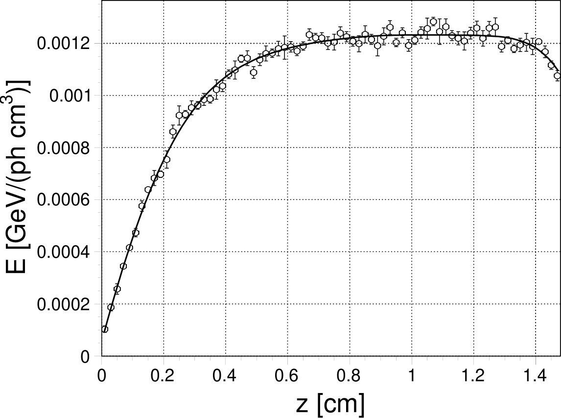 Figure 1
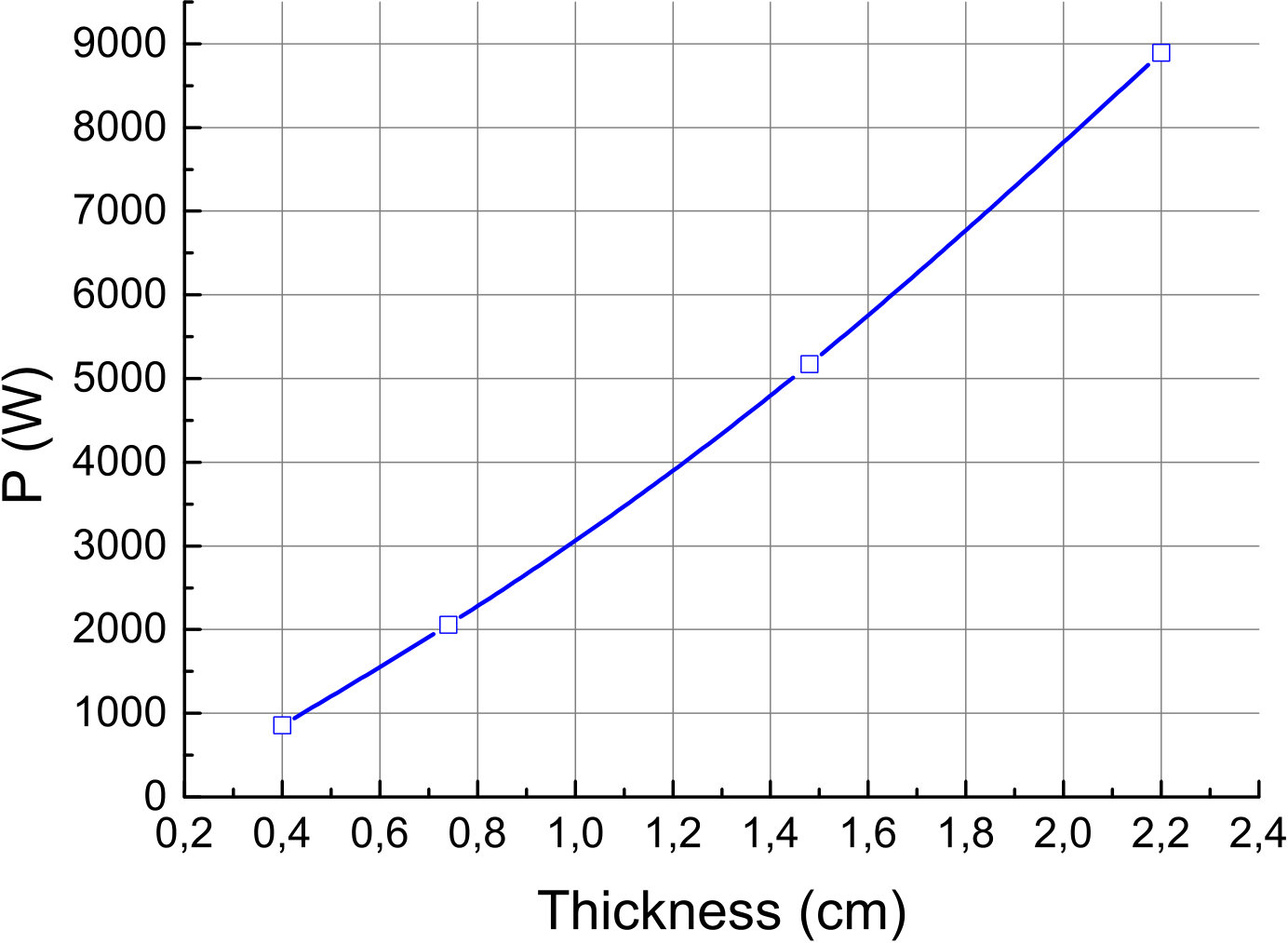 Figure 2
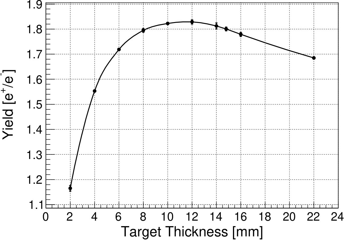 Figure 3
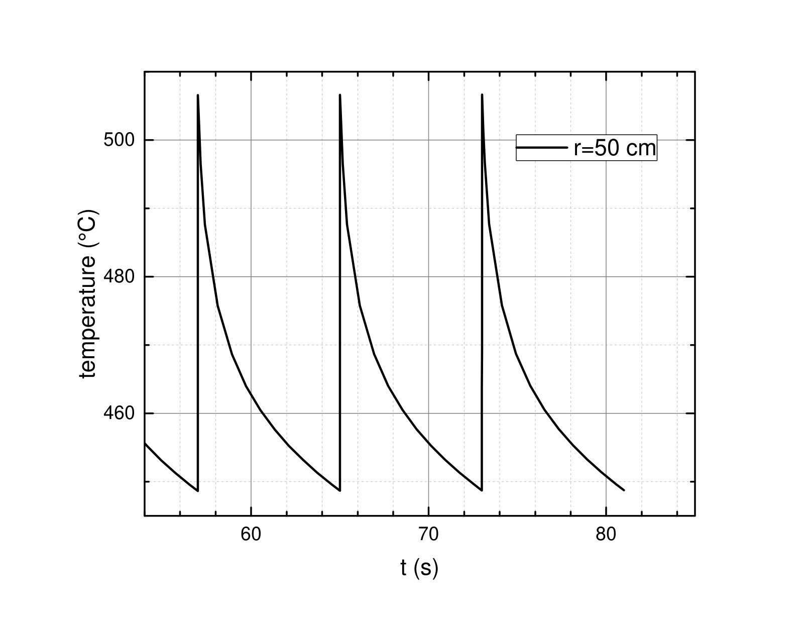 Figure 4
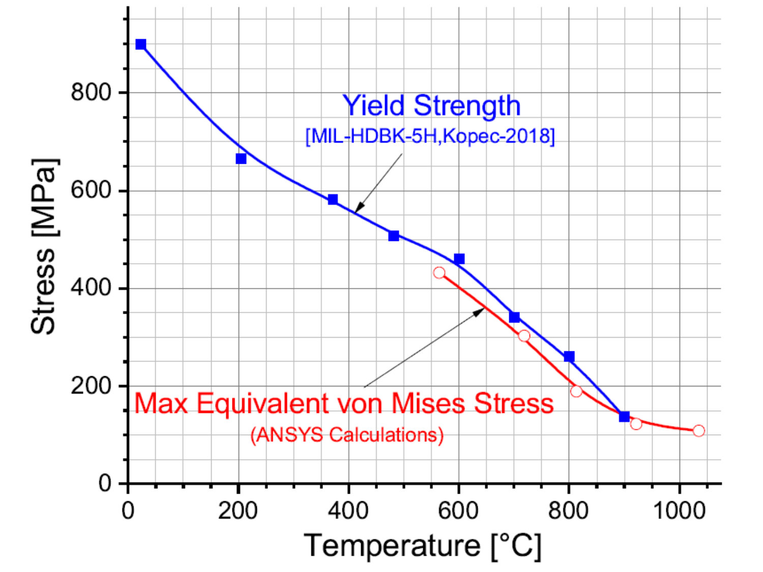 Figure 5
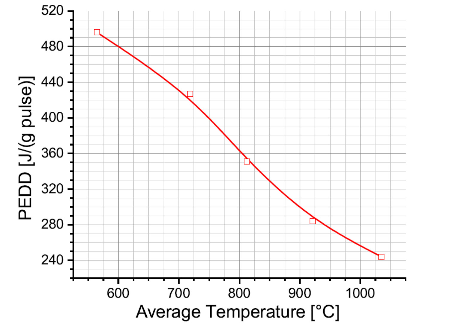 Figure 6
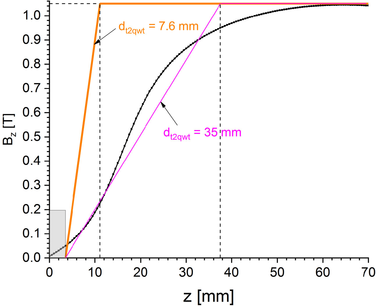 Figure 7
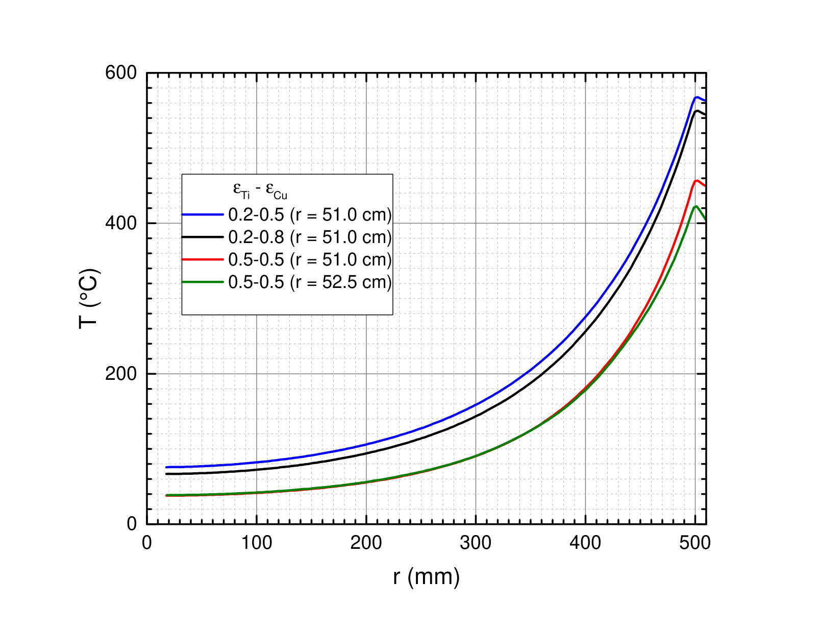 Figure 8
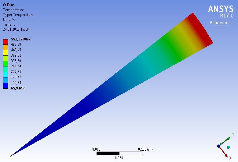 Figure 9
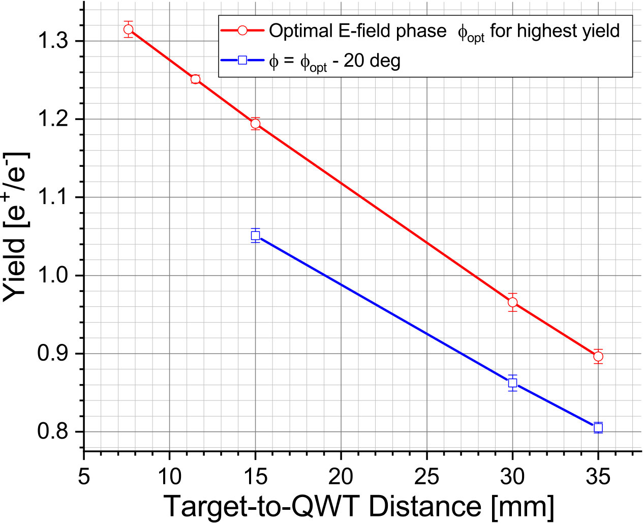 Figure 10
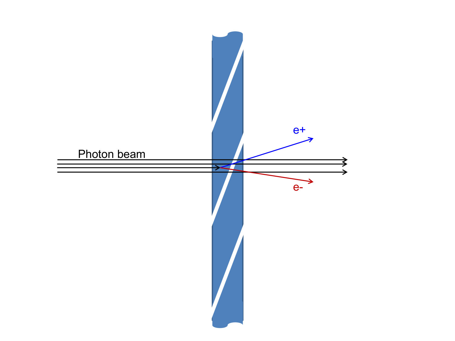 Figure 11
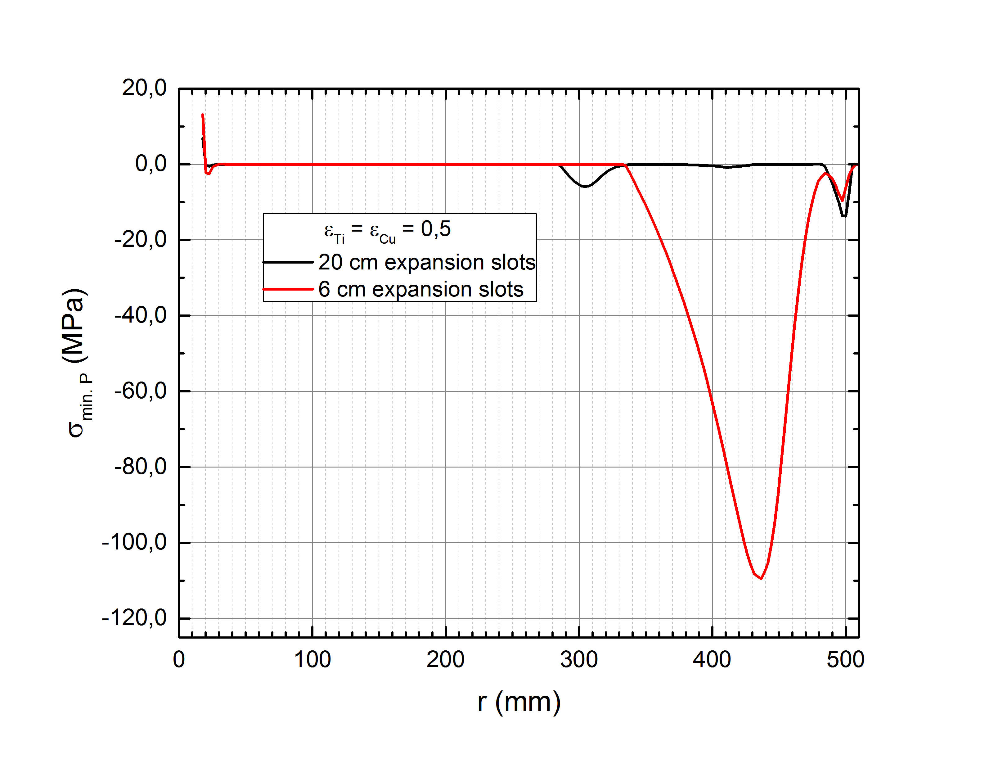 Figure 12
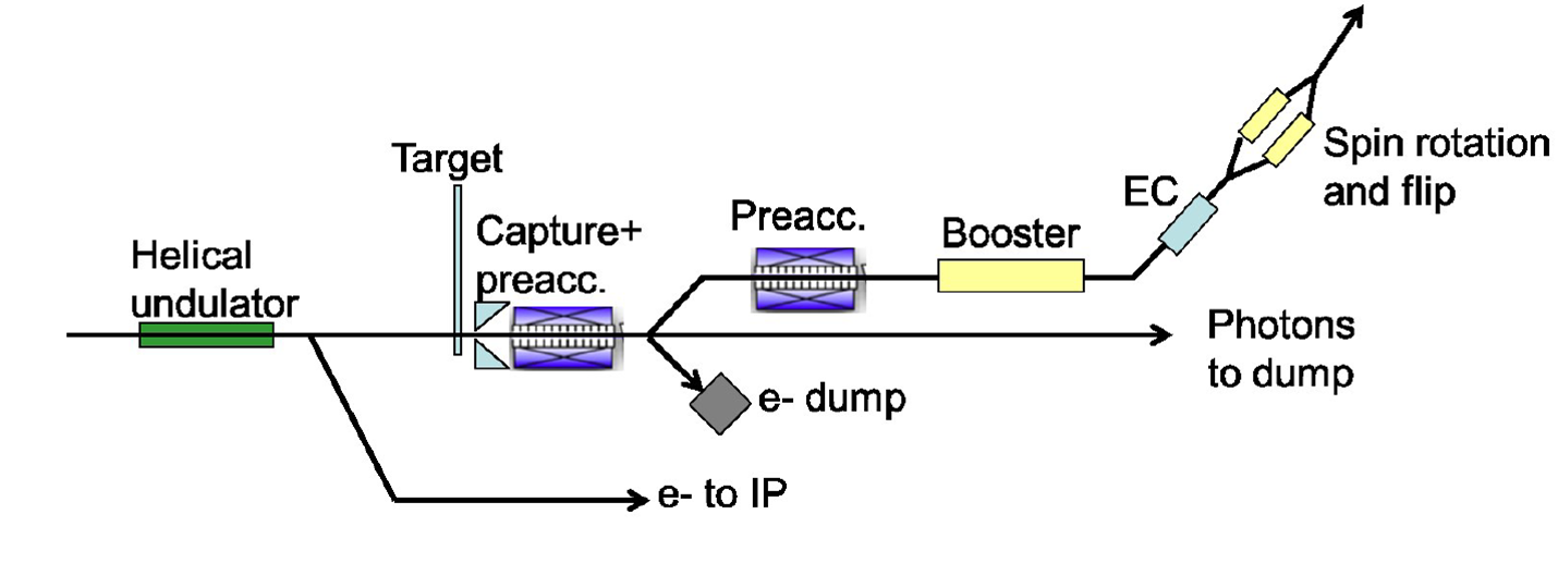 Figure 13
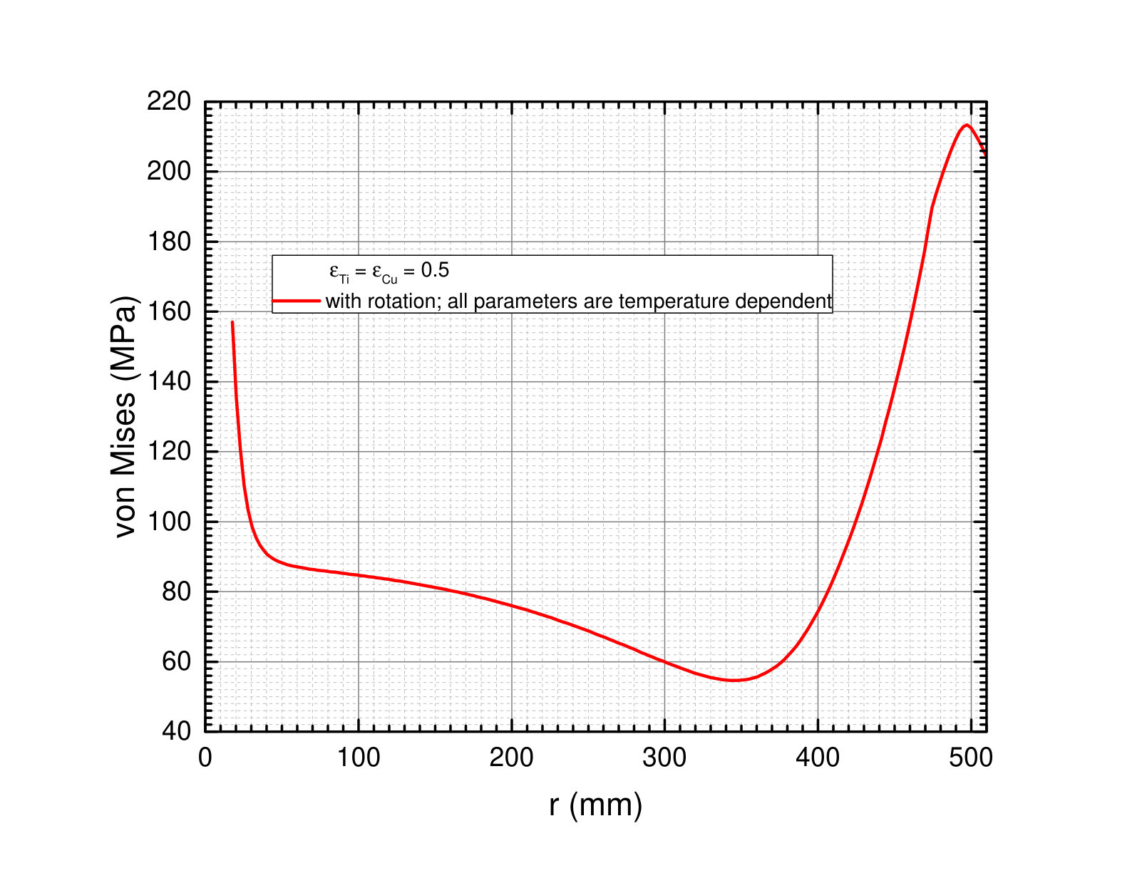 Figure 14
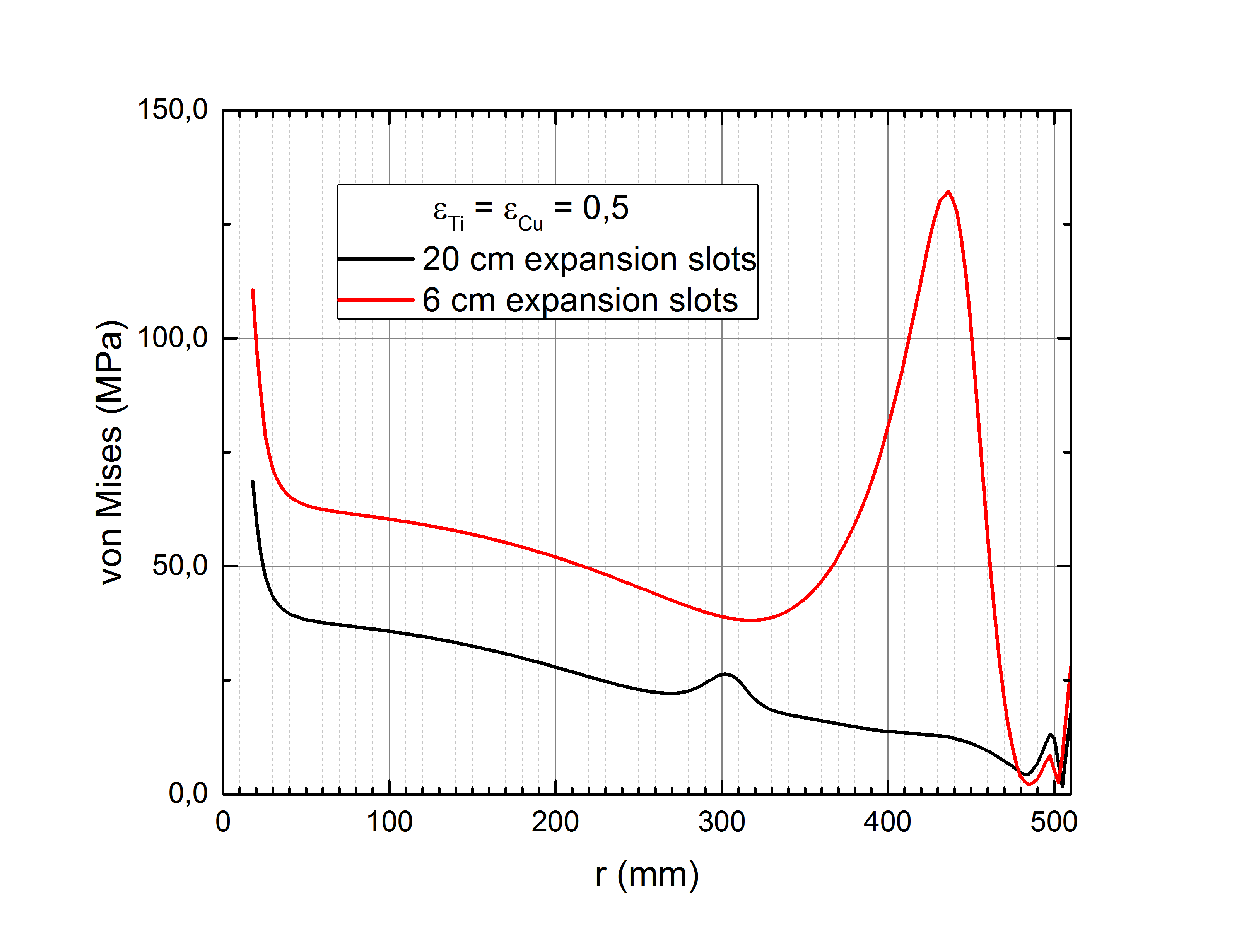 Figure 15
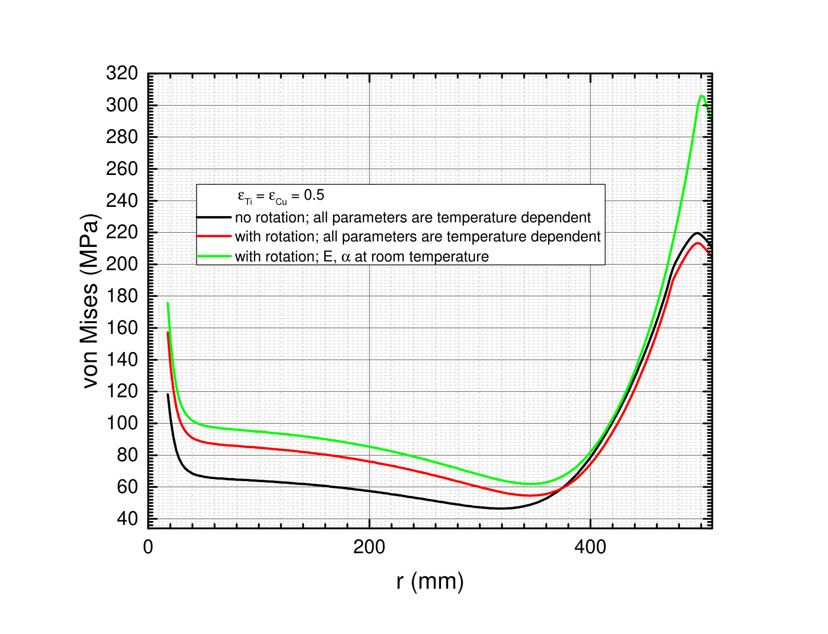 Figure 16
| FC | QWT | ||
| electron beam energy | GeV | 126.5 | |
| undulator active length | m | 231 | |
| space from middle of undulator to target | m | 401 | |
| undulator K | 0.85 | 0.92 | |
| photon yield per m undulator | /(em) | 1.70 | 1.95 |
| photon yield | /e- | 392.7 | 450.4 |
| photon energy (1st harmonic) | MeV | 7.7 | 7.2 |
| average photon energy | MeV | 7.5 | 7.6 |
| average photon beam power | kW | 62.6 | 72.2 |
| average power deposited in target | kW | 1.94 | 2.2 |
| rms photon beam spot size on target () | mm | 1.2 | 1.45 |
| PEDD in target per pulse (100 m/s) | J/g | 61.0 | 59.8 |
Peer Reviews
No public reviews on file for this paper yet. If you reviewed it on a platform where reviews are public (OpenReview, ICLR, NeurIPS, ICML), you can paste yours below so the community can read it here.
Videos
No videos yet. Explain this paper in a talk, walkthrough, or lecture? Add one.
Status of the undulator-based ILC positron source
F. Dietrich1, G. Moortgat-Pick2, S. Riemann1, P. Sievers3, A. Ushakov2
1*Deutsches Elektronen-Synchrotron (DESY), Platanenallee 6, D-15738 Zeuthen
2University of Hamburg, Luruper Chaussee 149, D-22761 Hamburg*
3CERN, CH-1211 Geneva 23, Switzerland corresponding author, [email protected]
Abstract
The design of the positron source for the International Linear Collider (ILC) is still under consideration. The baseline design plans to use the electron beam for the positron poduction before it goes to the IP. The high-energy electrons pass a long helical undulator and generate an intense circularly polarized photon beam which hits a thin conversion target to produce pairs. The resulting positron beam is longitudinally polarized which provides an important benefit for precision physics analyses. In this paper the status of the design studies is presented with focus on ILC250. In particular, the target design and cooling as well as issues of the optical matching device are important for the positron yield. Some possibilities to optimize the system are discussed.
.
1 Introduction
The positron production for a high-energy linear collider is a challenge; about positrons per second are required at the ILC collision point for nominal luminosity. The efficiency of positron production in a conversion target together with the capture acceleration of the positrons is not high. The load on the target and other source components as well as the radiation aspects are demanding issues for the optimization of positron sources for projects like ILC or CLIC.
The ILC positron production [1] is based on a long helical undulator passed by the high energy electron beam to create an intense circularly polarized photon beam. The photon beam hits a thin conversion target to produce electron-positron pairs; the resulting positron beam is longitudinally polarized. The target material is currently specified as Ti6Al4V. The target is designed as wheel of 1 m diameter spinning with 2000 rounds per minute in vacuum. This rotation speed is necessary to distribute the heat load from the intense, narrow photon beam to a larger volume of the target material during one ILC pulse. The capture system behind the target consists of an optical matching device followed by accelerator structures in a solenoidal 0.5 T field. Here, the parameters for the undulator-based positron source are considered in more detail with focus on ILC250. One important issue is the target cooling. Since water cooling turned out to be extremely complicated, cooling by thermal radiation is currently the favored option. Further, the choice of the capture optics is decisive for the positron yield. The status for the optimization of the positron source parameters is presented. Since the polarized positron beam is an outstanding feature of the ILC undulator source, in section 2 this benefit for physics measurements is shortly summarized. The following sections consider the design issues in detail. Focus is the load on the conversion target and its cooling. Since the load on the target depends on the efficiency of the capture system, also the positron yield is considered depending on the optical macthing device. Some possibilities to optimize the source parameters are discussed.
It should be mentioned that alternatively an electron beam of few GeV can be used to create pairs in a thick target. In reference [2] the application of such system for the ILC is suggested; the status and progress are described in [3]. However, the resulting positron beam will be unpolarized.
2 Polarization of positrons
Future high-energy linear colliders will probe the Standard Model and physics beyond with excellent precision. Electroweak interactions do not conserve parity, so beam polarization is essential to measure and to disentangle phenomena. High degrees of electron beam polarization are possible; the ILC e- beam will be at least 80% polarized. Since the generation of an intense (polarized) positron beam is a challenge, simultaneously polarized e- and e+ beams are under discussion since many years. Without going in details as physics processes and their analyses, the benefit of polarized positron beams is given by the following reasons (see also references [4, 6, 7]:
- •
There are 4 combinations of e+ and e- helicity states in the collision of high-energy electrons and positrons. Only with both beams polarized each of these initial state combinations can be explicitly realized in a collider.
- •
With the ’right’ helicity combination of initial states a higher effective luminosity is achieved: . A higher number of specific events is achieved in shorter running time. For example, assuming and the effective luminosity can be almost a factor 1.3 higher than without positron polarization. The availability of both beams polarized reduces therefore the required running time by one third.
- •
The suppression of background is crucial for precision measurements. With polarized beams the desired initial states can be enhanced or suppressed. This improves the discrimination and control of background processes.
- •
Polarized beams provide a high flexibility to evaluate systematic effects. It is very difficult to detect and correct time-dependent effects, correlations or a bias in the polarimeter measurement. If both beams are polarized, such systematic effects can be much better controled, and their impact on the uncertainty of observables can be substantially reduced down to negligable values.
- •
In case of deviations from the Standard Model predictions, polarization of both beams enhances significantly the possibility to confirm the existence of a new phenomenon: High precision, flexible configuration of initial states and a larger number of independent observables could even allow to unravel underlying physics.
- •
An independent determination of beam polarization and left-right asymmetries is possible but only if both beams are polarized.
One should keep in mind that also the zero polarization of an unpolarized positron beam must be confirmed to avoid any bias in the physics analyses [8].
All these arguments suggest that positron polarization is crucial already for ILC250. Detailed analyses demonstrate that with 2 ab*-1* and polarized e+ and e- beams a great Higgs physics program is offered: Many couplings can be measured with an uncertainty of 1% or better [8, 9]. This probes new physics phenomena complementary to the LHC. To achieve this precision with polarized electrons only, 5 ab*-1* are required.
3 The positron source parameters for ILC250
The ILC positron source is located at the end of the main linac. It consists of the helical undulator with maximum active length of 231 m, the conversion target made of Ti6Al4V, the optical matching device and the capture optics, acceleration, energy and bunch compression, spin rotation and spin flipper as shown in figure 1 and reference [1].
Since the photon energy and yield, and hence the positron yield depend strongly on the electron energy, the source performance has to be studied and optimized for each centre-of-mass energy. Goal is a positron yield of 1.5 e+/e- at the damping ring.
3.1 Superconducting helical undulator
Central part of the positron source is the superconducting helical undulator. A prototype was manufactured and tested in UK [10]. It consists of a 4 m long cryomodule with two 1.75 m long undulator modules. The undulator period is mm and the maximum B field is 0.86 T corresponding to a value . As described in the TDR, with 132 undulator modules (66 cryomodules) an active undulator length of 231 m is reached. With the quadrupoles foreseen every 3 cryomodules the undulator system reaches a total length of 320 m. The given undulator period, , and the maximum field on axis, , define the possible parameter range for the positron source, i.e. the undulator value, . The efficiency of positron generation in the target depends on the pair production cross section and hence on the photon energy. The cut-off for the first harmonic is related to the electron energy , and by
[TABLE]
i.e. lower K values increase the photon energy. The number of photons created per undulator length is
[TABLE]
implying that low values result in less photons. If the electron beam of the ILC250 machine is used for the positron production, a high value and the full active length of the undulator are required.
Also the beam spot size on the target depends on the opening angle of the photon beam,
[TABLE]
and it is very small even at a large distance from the undulator. The narrow photon beam causes a high peak energy deposition density (PEDD) at the target. To prevent overheating during one ILC pulse, the target is spinning with 100 m/s circumferential speed. Both, PEDD as well as the average power deposited in the target vary for different and depend on the distance between target and undulator. In previous studies the interplay of parameters has been studied for different centre-of-mass energies [14, 3, 11, 16, 15]. Most of these studies assumed a pulsed flux concentrator (FC) as optical matching device (OMD). A promising prototype study for the FC was performed by LLNL [17]. However, detailed studies showed that load at the inner part of the flux concentrator front side is high, at least too high for ILC250 [15]. This is mainly caused by the larger opening angle of the photon beam which is and the wider distribution of the shower particles downstream the target due to the lower photon energy at ILC250. To resolve this problem, the drift space between the middle of undulator and the target was reduced to 401 m. In addition, masks can be included to protect the OMD. Alternatively, a quarter wave transformer should be used which has a larger aperture than the FC; further details can be found in reference [15]. Table 1 presents an overview of the relevant parameters for the studies in this paper. The load on the target was simulated for FC and QWT. In both cases the positron beam polarization is 30%. However, the positron yield depends strongly on the magnetic field assumed for the simulations. The numbers in table 1 given for the QWT suppose an optimised shape of the B field; the maximum field of 1.04 T is achieved at distance of 8mm after the target exit instead of about 3.5 cm in the design given in reference [12]. More details are given in section 7.
4 Positron target wheel
4.1 Energy deposition
The photon beam hits the spinning target of Ti6Al4V, the photons undergo the pair production process in the field of nuclei, electrons and positrons are generated and exit the target. The energy deposition in the target as well as the number and energy of the exiting particles depend on the target thickness. For ILC500 a target thickness of 0.4 radiation length is recommended as described in the TDR. The energy deposition by a 120 GeV electron beam in the target was simulated with FLUKA [13]; the results are shown in figure 2 [16]. The energy deposition along z and also the positron yield are almost constant between 7 mm and 16 mm target thickness but the power deposited in the target increases. Taking into account the cooling of the spinning target, a target thickness of 7 mm is optimum.
4.2 Cooling by thermal radiation
As discussed in previous studies [1] the average energy deposition in the ILC positron target is about kW depending on the drive beam energy in the undulator, the target thickness and the luminosity (nominal or high). For ILC250, the average energy deposition in the target is 2 kW.
Since the initial investigations of the wheel, involving leak tight rotating vacuum seals and water cooling showed major problems [17, 18], an alternative technical solution was brought up to ensure the heat radiation as well as the safe rotation of 2000 rpm by magnetic bearings [36, 37]. This proposal was intensively investigated and many studies followed which are resumed here in this paper.
Few kW can be extracted by radiation cooling if the radiating surface is large enough and the heat distributes fast enough from the area of incident beam to a large radiating surface. Following the Stefan-Boltzmann law,
[TABLE]
with W/(cm K4), a radiating surface m2 is required to remove 2 kW if the average temperature is C and . For comparison: the area of a target rim with outer diameter cm and inner diameter cm is 0.36 m2 taking into account front and back side. With other words: The wheel spinning in vacuum can radiate the heat to a stationary cooler opposite to the wheel surface. It is easy to keep the stationary cooler at room temperature by water cooling. But it is crucial for the design that the heat distributes from the volume heated by the photon beam to a larger surface area. The thermal conductivity of Ti6Al4V is low, W/(cm K) at room temperatures and 0.126 W/(cm K) at 540∘C. The heat capacity is J/(g K) at room temperature and 0.126J/(g K) at 540∘C [19]. Although the wheel rotation frequency can be adjusted so that each part of the target rim is hit after 6-8 seconds, this time is not sufficient to distribute the heat load almost uniformly over a large area. For example: Following , the heat propagates mm during 6 seconds in Ti6Al4V. The heat is accumulated in the rim and the highest temperatures are located in a relatively small region around the beam path.
4.3 Wheel design options
Two options for the target wheel are currently under consideration:
The target wheel is a disk with the required target thickness. 2. 2.
The target wheel consists of a rim made of of the target material which is connected to a radiator with large surface made of material with good heat conductivity.
In case (1) the radiating surface is limited, and due to the low thermal conductivity the gradient along the radius is large. The thermal radiation is quite low from the inner surface with low radii. So, option (1) is recommended for lower energy deposition.
In case (2) the radiating surface can be easily increased by fins. The target rim needs a minimum size to cover the electromagnetic shower for the pair-production; it will have a substantially higher temperature than the radiator. The fins will be worked from material with high thermal conductivity to speed-up the heat extraction. Such construction could be necessary in case of higher energy deposition, e.g. in case of high luminosity or polarization upgrade.
To reduce high thermal stress along the rim in the beam path area as expected for high average temperatures, the target could be manufactured in sectors which can expand. In a disc this can be realized by radial expansion slots. For the final construction of the target wheel FEM design studies are necessary to ensure a long-term operation followed by systematic tests using a mock-up. Here, for ILC250 option (1) is considered. For the FEM studies all material parameters were taken into account temperature dependent. They are summarized in references [14, 3] and taken from [22, 20, 21, 19]
4.4 Driving mechanism and bearing
The wheel design is determined by the energy deposition and cooling efficiency. For the final construction also the bearing, the drive motor etc. are important. This is not considered here since first the load and the cooling specifications must be worked out before the engineering design will be finalized. Magnetic bearings, used for fly wheels for energy storage, for vacuum pumps and for Fermi Choppers have been developed, and are available on the market (SKF, Kernforschungszentrum Juelich). Usually, they base on permanent magnet technology. They can be adapted to the operating conditions of the rotating Titanium wheel for positron production. Breidenbach et al. [24] have studied a bearing, based on electro-magnetic coils. Both solutions should be feasible for the target wheel but further R&D is necessary.
The heating of the target yields a non-uniform temperature distribution and stress within the wheel. At a first glance [26], the corresponding deformation due to expansion does not yield imbalances of the spinning wheel. So far, the dynamic effects have not yet considered in detail. Comprehensive simulations are planned to study them in order to prepare a reliable wheel design.
4.5 Safety issues
The energy stored in the wheel is
[TABLE]
where is the moment of inertia. Assuming a full disk of 52 cm radius and 2000rpm, about 72 kJ are stored in the wheel considered here for ILC250. Appropriate housing is required. Due to the short distance between OMD and target a protection of the OMD against mechanical crash of the target seems impossible.
5 Load distribution in the target
5.1 Temperature distribution
The temperature distribution in the target wheel determines the stress development in the target. At elevated temperatures the material will expand. Since the temperature gradient along the radius is large the highest thermomechanical stress is expected in the rim region where the beam impinges.
Simulations with ANSYS [25] were performed to study the temperature distribution and the corresponding thermal stress. The temperature dependence of the material parameters (thermal conductivity, heat capacity) was taken into account (see also reference [14]). The target is assumed as disk with thickness 7 mm. The temperaure distribution was studied for various emissivities of target and cooler surface.
The radial temperature distribution in the disc is shown in figure 3. It summarizes representative radial temperature profiles depending on the emissivities of the target and cooler material for a solid disc of 51 cm and 52.5 cm radius; the beam hits the target at a radius of 50 cm. Larger wheel radii increase slightly the radiative area in the hot rim region and decrease the maximum temperature.
We also tested the influence of the distance between target surface and cooler which affects the radiating geometry in the hot rim region. It was found that this influence on the temperature is almost negligible.
The emissivity of the Ti6Al4V target sample used in the irradiation experiment at MAMI was measured to . So it is expected that at least target and cooler surfaces with emissivities of 0.5 are feasable. This would result in an effective emissivity of for the thermal radiation. As shown in figure 3, in such case the maximum average temperature is roughly 460∘C.
An optimization of the emissivities by surface processing or coating should be possible. Such scenarios are not yet taken into account and let room for improvement of the target cooling performance.
5.2 Cyclic load
In addition to the high average temperatures in the rim region the photon beam creates cyclic load in the target which happens every 6-8 seconds at the same position, depending on the wheel revolution frequency. The photon beam causes an instantaneous temperature rise which adds up to roughly 80-100 K (nominal luminosity) to the average temperature. Also for low emissivities the resulting peak temperature occurs only locally for short time and does not exceed 600–650∘C.
The cyclic temperature in the target rim caused by the beam impact is shown in figure 4 for an effective emissivity of (). The cyclic load creates peak temperatures up to 510∘C; the maximum average temperature is 460∘C.
It was a very important result from experimental tests described in section 6 to see that no serious damage was obtained even up to temperatures close to the phase transition point (almost 1000∘C.). However, the experimental test did not take into account any load from a moving target.
5.3 Stress in the target wheel
The high average temperature in the target rim as well as the cyclic load induce high stress due to thermal expansion. To reduce the thermal stress in the target, expansion slots can be cut into the wheel. The temperature distribution remains almost unchanged but the stress is substantially reduced (see also [14]). For the studies of the stress development in the target wheel radial expansion slots of 6 cm and 20 cm were assumed; the distance between two slots corresponds to the beam path during one ILC pulse. If a wheel with such slots is operated the wheel rotation frequency has to be synchronized with the beam pulses. This will avoid that the photon beam hits a gap resulting in a short dip in the luminosity during one pulse.
The target rotation with Hz increases the stress in the wheel in radial () and tangential () direction. Following classical treatment given in text books [38, 39] for forces in spinning wheels, the stress at the radius is given by
[TABLE]
with the inner and outer radius and , the density and Poisson’s ratio . The target rotation increases the stress in the hot target region only little: for a wheel with cm the radial stress at the beam path radius (cm) is 1.4 MPa, the hoop stress along the beam path is 8.7 MPa. The maximum hoop stress occurs at the inner wheel radius and is about 40 MPa. The maximum radial stress is located at , i.e. at cm depending on cm. In this region the temperature is about 100∘C. For the simple wheel geometry without expansion slots these results agree well with that of ANSYS simulations. A summary of the stress distributions simulated with ANSYS for a wheel without or with expansion slots is given in figures 5 and 6. In case of expansion slots the highest stress is obtained at the radius where the slots end. The stress in figure 6 is given along a radial line in the middle between two slots.
The average thermal stress and the cyclic load by the beam impact add up. Maximum values are reached without expansion slots; they amount to about 300 MPa. The stress in the wheel is compressive.
5.3.1 Expansion slots
As mentioned, expansion slots reduce substantially the stress in the target rim. However, if the distance between the slots is not sunchronized with the bunch length and rotation speed of the target wheel, the positron production is not constant during one bunch train. Many but narrow slots, i.e. substantially smaller than the beam spot, would avoid the synchronisation of wheel rotation frequency and incident photon beam pulses. But fluctuations in the luminosity will remain. Inclined slots as shown in figure 7 could be a solution: the photon beam passes always the constant target thickness; the fluctuations in the positron production should be negligable.
Further studies are necessary to evaluate the benefit and optimum shape of expansion slots. In particular, these studies have to take into account the mechanical stability at elevated temperatures.
5.4 Target wheel cooling and OMD
The optical matching device should be installed as close as possible to the target. This could cause a magnetic field in the target which induces eddy currents in the spinning wheel. These currents increase the target temperature [31] and could slightly drag the wheel rotation; more details are discussed in section 7.
The OMD has a radius of about cm and occupies a quite large part of the target surface. When the hot target passes this OMD area, the heat radiates to the OMD and not to the cooler surfaces. The results presented above do not take into account the somewhat lower cooling efficiency in the OMD. Either the OMD can be cooled excellently or the target temperatures increase slightly. The heat load in the OMD due to the radiating target has to be taken into account for its final design, also with regard to the particle shower which deposits energy in the OMD too.
6 Target material test
It is an essential question whether the target material stands the high thermal and mechanical load. The instantaneous load repeats up to times at the same target position within 1 year of ILC operation, so that also the fatigue limits must be considered. Further, the target is passed by a photon beam which could change the material properties by damaging the material structure. To study this complex of questions, experimental tests were performed. To simulate a load corresponding to that expected at the ILC positron target, the electron beam (14 MeV and 3.5 MeV) of the Mainz Mictrotron (MAMI) injector was used. It was managed to focus the rms spot size of the 14 MeV electron beam on target to mm for the chopped 50 A cw electron beam with pulse length of 2 ms [27]. The 2 ms pulse produced in Ti6Al4V samples (1 mm and 2 mm thickness) load conditions as expected at the ILC target. With a repetition rate of 100 Hz up to load cycles were generated correspnding to about 2 years ILC running. All samples survived the irradiation procedure without damage visible by eyes. The grain structure was modified in samples that reached maximum temperatures near to the phase transition value. For the details see reference [28]. It was concluded that the operation of a positron target consisting of Ti6Al4V is possible if the maximum temperature corresponds to the recommended operation temperature and exceeds only locally for short time this level up to about C. These results were confirmed irradiating thin samples of about m thickness with the 3.5 MeV electron beam. The strongly focused beam allowed a temperature rise by K within a ms pulse. Due to the fast repetition rate of the pulses (up to 100-140 Hz) the average temparature at the considered location of the material reached C. The detailed analys including structural changes ist still omgoing. But with a laser microscope dimensional changes or visible modifications have not been obtained. Only if the the full power of the electron beam was shortly directed for few seconds to the sample so that immediately temperatures near and above C were achieved buckling was abserved. Wholes in the smples have not been obtained. Although the studies are not yet finalized it is clear that high temperature Ti alloys as Ti6Al4V are well suited as target material. Very high temperature Titanium alloys, for example Ti SF-61 could be an alternative as suggested in reference [24]; the Titanium alloy SF-61 stands higher operation temperatures than Ti6Al4V.
6.1 Load limits in Ti6Al4V
High temperature titanium alloys are ductile materials. The temperatures reached in the positron target or on potential exit windows made of Ti alloys rise the question for the limit to plastic deformations. Plastic deformations must be avoided since they could cause imbalances in the spinning wheel arrangement.
To study this question, temperature dependent elasticity and hardening data were added to the material properties in ANSYS and compared with the results of the material tests at MAMI in Mainz. This allows to estimate temperature and stress at which the material starts to deform plastically. The simulations have shown that the maximum equivalent stress for elastic deformation due to a particle beam in Ti6Al4V is approximately 10% below the yield strength. At a temperature of C the transition from elastic to plastic deformation occurs if the equivalent von Mises stress reaches 400 MPa. At higher temperatures the limits go down quickly, for example, at C average temperature, the equivalent stress has to be below 200 MPa. The results of this study are summarized in figure 8, more details can be found in reference [29]. Figure 8 presents the maximum allowed thermal stress as well as the allowed peak energy deposition density (PEDD) as function of the temperature in Ti6Al4V.
The load expected in the target wheel (see section 5.3) is safely below the limit for plastic deformation.
Further studies are needed to include also creep effects. Also the impact of potential radiation damage must be understood.
7 Positron yield and OMD
During the long time of desgn studies for the ILC positron source several options for the OMD have been considered. An overview is given in reference [12]. The best solution would be a pulsed flux concentrator which initially was envisaged for the adiabatic matching device (AMD). But in further detailed studies it appeared that over the long pulses of about 1 ms the field in the FC could not be kept stable in time [3]. Further, studies [15] showed that the peak energy deposition in the center at the front of the FC is too high for ILC250. Neither a larger FC aperture nor a shorter distance of FC to undulator could improve the situation substantially. Therefore, further studies were pursued with a QWT. Following reference [12], only a yield ee- can be reached for electron beam energies of 125 GeV. Studies [15] showed that for the thinner conversion target, a maximum K value () and an optimized B field the yield can be increased to the required value. Figure 9 demonstrates the influence of the magnetic field shape on the positron yield. If the magnetic field rises from almost zero at the target exit within 8 mm to a maximum value of 1.04 T, a yield of about 1.5e+/e- can be reached for high values.
It is the question whether a QWT with the corresponding optimum magnetic field is possible, i.e. maximum field of T at a distance of 7–8 mm from the target and almost zero at the target. A magnetic field on the target creates eddy currents which heat the target. Even if the heating is not important, brake effects have to be conserdered and taken into account for the final design and construction of the wheel.
7.1 Magnetic field in target
Studies have shown that a high magnetic field at the target increases substantially the positron yield. However, the drawback of a high field are the eddy currents created in the spinning target. They induce additional heat deposition and stress and brake the target rotation. In addition, also the magnetic field in the target depends on the eddy current and influences the positron distribution at the target exit. This effect has not been considered in the simulations.
The impact of eddy currents on a target wheel has been studied with simulations and in experiments [32, 33]. The experiment described in reference [32] used a wheel prototype made of 1.56 mm thick Ti6Al4V rim with spokes. The torque associated with eddy current production was measured for a range of immersion depths and magnetic flux densities. The measured torque values correspond to heat loads of up to 4.7 kW when operating in fields of approximately 1 T at 1500 rpm, extrapolating to 8.0 kW at 2000 rpm. Based on this result it was recommended to keep the magnetic field at 0.5 T or below at the ILC target exit.
If the magnetic field is pulsed the loads decrease enormously: Since the pulses are short and the repetion rate is 5 Hz, the average power is reduced to only 1-2% compared to a DC magnet. Only very recently a proposal has been made [34] to use a pulsed solenoid, similar to that used for LEP and other positron sources, which with sufficiently long pulses of at most 4 ms duration can provide a field of up to 4 T and stable in time over the duration of the beam pulse of 1 ms. Increase of positron yield could be within reach.
The pulsed operation would lead also to an acceptable heat load from the solenoid into the rotating wheel by induced currents inside the target. These currents could be further cut by laminating the target rim, by introducing radial cuts into the rim of the wheel. These studies will be pursued in the next future.
8 Optimized undulator parameters for ILC250
In case that the QWT is the OMD, the positron yield could be too low, i.e. ee-. A longer undulator is not recommended. One reason is the photon beam emission angle: The opening angle of the photon beam is proportional to , i.e. for ILC250 a relatively high energy deposition could be possible in the walls of a long superconducting undulator. To protect the undulator walls and the vacuum, masks will be inserted, preferably at the position of the quadrupoles [40]. However, for long undulators, the modules at the end suffer from photons with energies of few MeV (see more details in reference [41]. To absorb these photons, relatively long masks are required which also have to prevent that shower particles from the masks enter the undulator aperture and degrade the vacuum. This problem is under study.
It could be more efficient to optimize the undulator and photon beam parameters for the ILC250 option. The reduction of the undulator period to 10.5 mm or even 10 mm increases the energy of the photons (see equation 1). The cross section of the pair production process increases with the photon energy; for example, in Ti the pair production cross section at 10 MeV is about 25% higher than at 7.5 MeV. Lower periods imply lower values for constant , and smaller values reduce the number of photons, see equation (2). However, the higher photon energy increases the rate of pair production in the target and could compensate the lower photon number so that the required positron yield can be reached even for a shorter undulator.
Rough estimates demonstrated that for ILC250 the active length of the undulator could be reduced to about 200 m for mm and to 180 m for mm.
In general, with lower values the relative contribution of higher harmonics goes down, and the photon distribution is more focused to the axis. This also could reduce the power deposition in the undulator walls. To re-optimize the undulator parameters detailed studies will include the realistic undulator modules with errors in B field and period. In addition, the target thickness should be adopted accordingly to find the optimum choice for the positron yield, the load and the cooling efficiency for the target.
9 Summary
Studies are performed to design the undulator-based ILC positron source which will generate a polarized positron beam. The design studies have made considerable progress over the past years, no show stoppers have appeared. Stategies for technical developments, prototyping and laboratory tests have been laid out (see, for instance, references [3, 34, 35]. Thus this design can be considered as solid and is to be pursued rigorously in the next future.
Main issue is the positron target wheel cooled by thermal radiation. It was shown that such a target will work. However, also the positron capture, in particular the OMD, are crucial for the positron source performance and need still R&D work. All studies done so far base on the helical undulator prototype [10]. Further optimization of the undulator parameters could help to improve substantially the positron source. The almost final paramemeters for all components of the positron soure, i.e. undulator, target and OMD should be fixed as soon as possible to develop also the engineering design for a full functioning target wheel and positron capture complex.
Acknowledgment
This work was supported by the German Federal Ministry of Education and Research, Joint Research Project R&D Accelerator “Positron Sources”, Contract Number 05H15GURBA.
The reference list from the paper itself. Each links out to its DOI / PubMed record.
- 1[1] T. Behnke et al. , “The International Linear Collider Technical Design Report - Volume 1: Executive Summary,” ar Xiv:1306.6327 [physics.acc-ph]; C. Adolphsen et al. , “The International Linear Collider Technical Design Report - Volume 3.I: Accelerator R&D in the Technical Design Phase,” ar Xiv:1306.6353 [physics.acc-ph]; C. Adolphsen et al. , “The International Linear Collider Technical Design Report - Volume 3.II: Accelerator Baseline Design,” ar Xiv:1306.6328 [physics.acc-ph].
- 2[2] T. Omori et al. , Nucl. Instrum. Meth. A 672 (2012) 52, ar Xiv:1110.1450 [physics.acc-ph].
- 3[3] K. Yokoya (ed.), Positron Working Group, W. Gai et al. , Report on the ILC Positron Source , May 23, 2018.
- 4[4] G. Moortgat-Pick et al. , Phys. Rept. 460 (2008) 131 doi:10.1016/j.physrep.2007.12.003 [hep-ph/0507011]; G. A. Moortgat-Pick and H. M. Steiner, Eur. Phys. J. direct 3 (2001) no.1, 6 doi:10.1007/s 1010501 c 0006 [hep-ph/0106155]; T. Hirose et al. , Nucl. Instrum. Meth. A 455 (2000) 15. doi:10.1016/S 0168-9002(00)00686-0.
- 5[5] G. Moortgat-Pick et al. , Eur. Phys. J. C 75 (2015) no.8, 371 doi:10.1140/epjc/s 10052-015-3511-9 [ar Xiv:1504.01726 [hep-ph]].
- 6[6] R. Karl and J. List, ar Xiv:1703.00214 [hep-ex].
- 7[7] R. Karl, Ph D Thesis ’From the Machine-Detector Interface to Electroweak Precision Measurements at the ILC’ , University of Hamburg, February 2019.
- 8[8] K. Fujii et al. , ar Xiv:1801.02840 [hep-ph].