Huygens' Dipole for Polarization-Controlled Nanoscale Light Routing
Sergey Nechayev, J\"org S. Eismann, Martin Neugebauer and, Pawe{\l} Wo\'zniak, Ankan Bag, Gerd Leuchs, Peter Banzer

TL;DR
This paper demonstrates polarization-controlled nanoscale light routing using Huygens' dipoles, achieving high directivity in TM and TE modes, enabling advanced optical applications.
Contribution
It introduces a novel approach to polarization-controlled light routing via Huygens' dipoles, with experimental validation of high directivity in nanoantennas.
Findings
Achieved ~23 dB directivity in TM mode
Achieved ~18 dB directivity in TE mode
Demonstrated polarization selectivity for unidirectional coupling
Abstract
Structured illumination allows for satisfying the first Kerker condition of in-phase perpendicular electric and magnetic dipole moments in any isotropic scatterer that supports electric and magnetic dipolar resonances. The induced Huygens' dipole may be utilized for unidirectional coupling to waveguide modes that propagate transverse to the excitation beam. We study two configurations of a Huygens' dipole -- longitudinal electric and transverse magnetic dipole moments or vice versa. We experimentally show that only the radially polarized emission of the first and azimuthally polarized emission of the second configuration are directional in the far-field. This polarization selectivity implies that directional excitation of either TM or TE waveguide modes is possible. Applying this concept to a single nanoantenna excited with structured light, we are able to experimentally achieve…
Click any figure to enlarge with its caption.
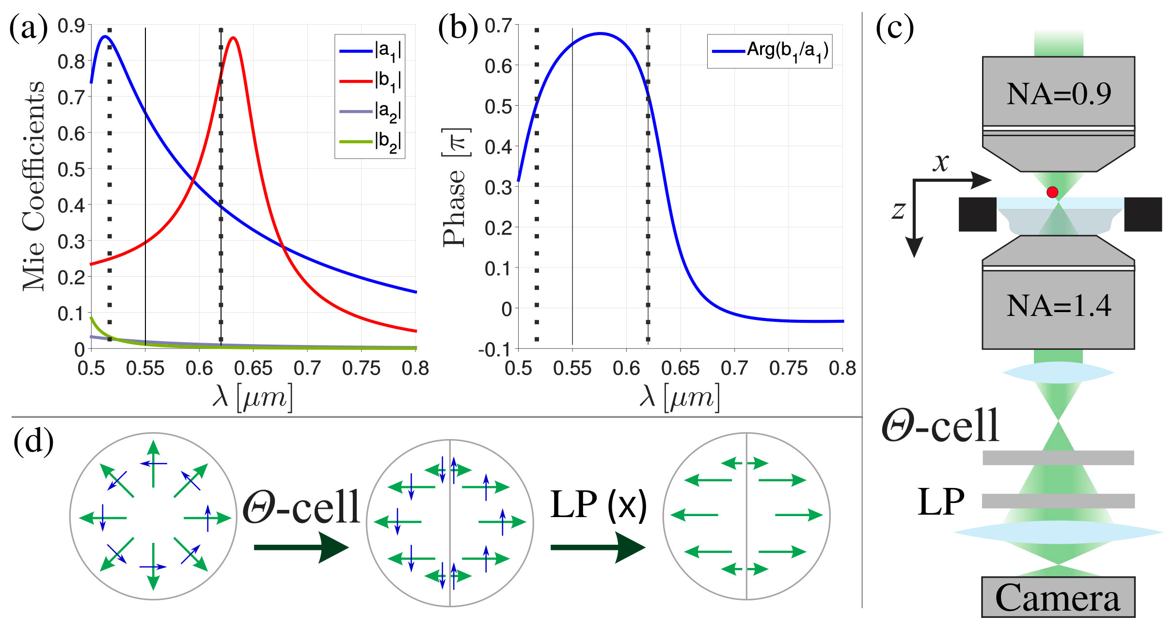 Figure 1
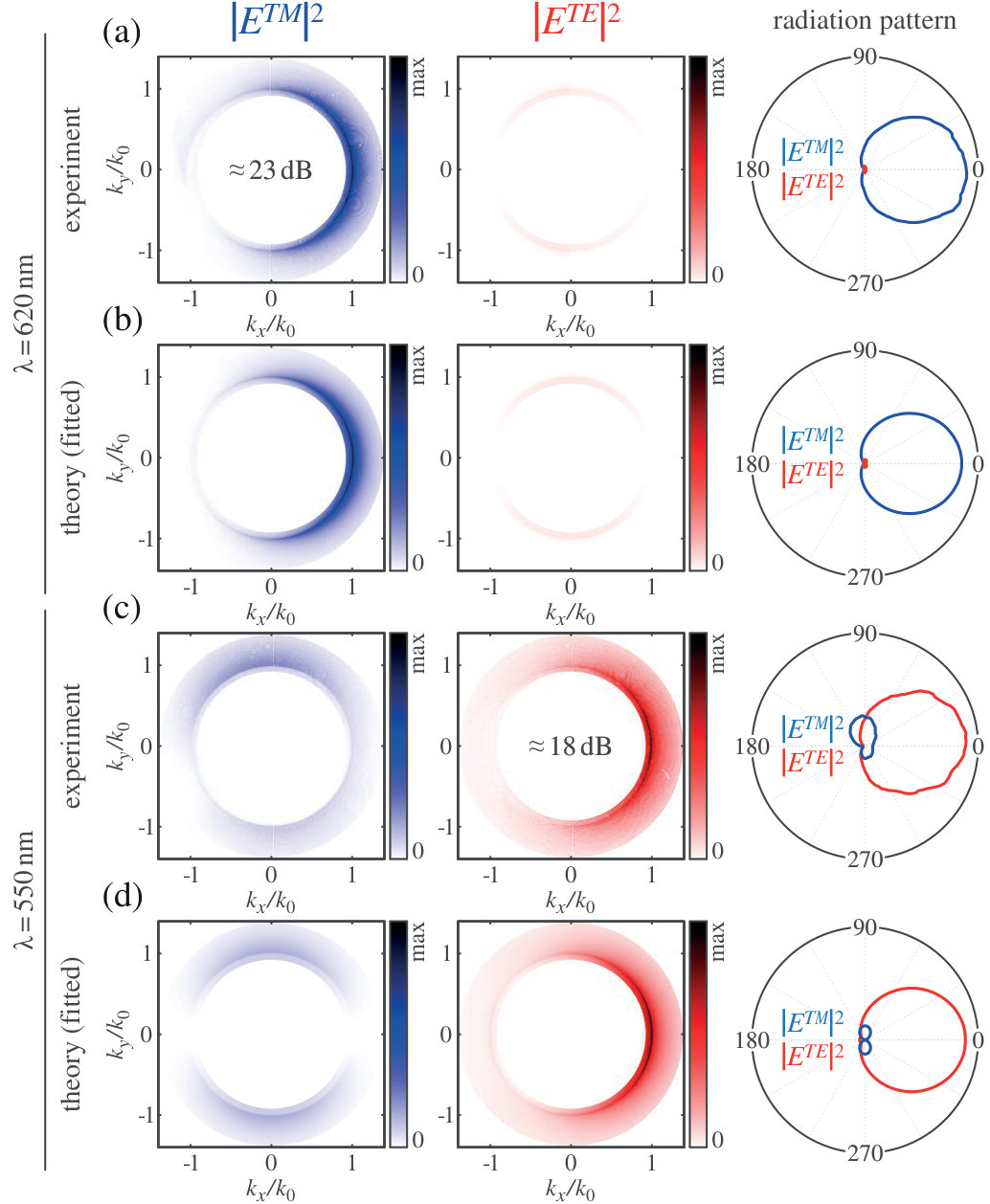 Figure 2
| 620 | 0 | 1 | 0 | 0 | ||
| 550 | 0 | 0 | 0 | 1 |
Peer Reviews
No public reviews on file for this paper yet. If you reviewed it on a platform where reviews are public (OpenReview, ICLR, NeurIPS, ICML), you can paste yours below so the community can read it here.
Videos
No videos yet. Explain this paper in a talk, walkthrough, or lecture? Add one.
Huygens’ Dipole for Polarization-Controlled Nanoscale Light Routing
Sergey Nechayev
Max Planck Institute for the Science of Light, Staudtstr. 2, D-91058 Erlangen, Germany
Institute of Optics, Information and Photonics, University Erlangen-Nuremberg, Staudtstr. 7/B2, D-91058 Erlangen, Germany
Jörg S. Eismann
Max Planck Institute for the Science of Light, Staudtstr. 2, D-91058 Erlangen, Germany
Institute of Optics, Information and Photonics, University Erlangen-Nuremberg, Staudtstr. 7/B2, D-91058 Erlangen, Germany
Martin Neugebauer
Max Planck Institute for the Science of Light, Staudtstr. 2, D-91058 Erlangen, Germany
Institute of Optics, Information and Photonics, University Erlangen-Nuremberg, Staudtstr. 7/B2, D-91058 Erlangen, Germany
Paweł Woźniak
Max Planck Institute for the Science of Light, Staudtstr. 2, D-91058 Erlangen, Germany
Institute of Optics, Information and Photonics, University Erlangen-Nuremberg, Staudtstr. 7/B2, D-91058 Erlangen, Germany
Ankan Bag
Max Planck Institute for the Science of Light, Staudtstr. 2, D-91058 Erlangen, Germany
Institute of Optics, Information and Photonics, University Erlangen-Nuremberg, Staudtstr. 7/B2, D-91058 Erlangen, Germany
Gerd Leuchs
Max Planck Institute for the Science of Light, Staudtstr. 2, D-91058 Erlangen, Germany
Institute of Optics, Information and Photonics, University Erlangen-Nuremberg, Staudtstr. 7/B2, D-91058 Erlangen, Germany
Peter Banzer
[email protected] [ Max Planck Institute for the Science of Light, Staudtstr. 2, D-91058 Erlangen, Germany
Institute of Optics, Information and Photonics, University Erlangen-Nuremberg, Staudtstr. 7/B2, D-91058 Erlangen, Germany
(March 2, 2024)
Abstract
Structured illumination allows for satisfying the first Kerker condition of in-phase perpendicular electric and magnetic dipole moments in any isotropic scatterer that supports electric and magnetic dipolar resonances. The induced Huygens’ dipole may be utilized for unidirectional coupling to waveguide modes that propagate transverse to the excitation beam. We study two configurations of a Huygens’ dipole – longitudinal electric and transverse magnetic dipole moments or vice versa. We experimentally show that only the radially polarized emission of the first and azimuthally polarized emission of the second configuration are directional in the far-field. This polarization selectivity implies that directional excitation of either TM or TE waveguide modes is possible. Applying this concept to a single nanoantenna excited with structured light, we are able to experimentally achieve scattering directivities of around 23 dB and 18 dB in TM and TE modes, respectively. This strong directivity paves the way for tunable polarization-controlled nanoscale light routing and applications in optical metrology, localization microscopy and on-chip optical devices.
pacs:
03.50.De, 42.25.Ja, 42.50.Tx
I Introduction
In 1983, Kerker et al. predicted directional antenna-like scattering by magneto-dielectric particles Kerker et al. (1983) owing to the interference of the excited in-phase perpendicular electric and magnetic dipole moments. Such dipole source was termed Huygens’ dipole and it is associated with increased forwardsuppressed backward scattering Geffrin et al. (2012); Person et al. (2013). The prediction of directional scattering under plane-wave illumination, supported by experimental demonstrations Geffrin et al. (2012); Fu et al. (2013); Person et al. (2013), and multipolar generalized versions of it Alaee et al. (2015); Pors et al. (2015); Wei et al. (2017); Liu and Kivshar (2018); Kruk and Kivshar (2017) turned out to be seminal in the field of optical antennas Mühlschlegel et al. (2005); Bharadwaj et al. (2009); Novotny and van Hulst (2011); Krasnok et al. (2012, 2013). Considerable efforts have been made to confine the radiated power by single nano-antennas Nieto-Vesperinas et al. (2011); Coenen et al. (2011); Rolly et al. (2012); Coenen et al. (2014); Wiecha et al. (2017); Picardi et al. (2018) and metasurfaces Staude et al. (2013); Decker Manuel et al. (2015); Arslan et al. (2017); Langguth et al. (2015) into an even narrower angular range. These directive nano-antennas coupled to single emitters allow for controlling the emission intensity distribution Gersen et al. (2000); Taminiau et al. (2008a, b); Curto et al. (2010, 2013); Hancu et al. (2014); Langguth et al. (2015) and polarization Kruk et al. (2014); Ren et al. (2015); Cotrufo et al. (2016); Yan et al. (2017).
Inducing a Huygens’ dipole in a nanoparticle under plane-wave illumination requires that the nanoparticle has equal first order electric and magnetic Mie coefficients Kerker et al. (1983). Importantly, a dipolar scatterer responds only to the local electric and magnetic fields, while Maxwell’s equations locally permit any configuration of these electromagnetic field vectors Abouraddy and Toussaint (2006); Yang and Cohen (2011). Consequently, structured illumination allows for exciting Woźniak et al. (2015) an arbitrary oriented Huygens’ dipole in any isotropic dipolar scatterer (assuming ) and, hence, unidirectional scattering along any axis. The first experimental observation of a Huygens’ dipole that emits light directionally transverse to the propagation direction of the excitation beam was reported recently Neugebauer et al. (2016); Bag et al. (2018) using structured illumination and a Si nanoparticle with , while the relative phase between Mie coefficients compensated for the inherent phase of the structured excitation field Neugebauer et al. (2014); Aiello et al. (2015). The observed phenomena was referred to as “transverse Kerker scattering”.
In this communication, we report on an experimental polarization resolved quantitative study of transverse Kerker scattering phenomena using a spatially varying cylindrical polarization basis. We utilize two possible realizations of a Huygens’ dipole — an in-phase longitudinal electric and transverse magnetic dipole moments (i) and vice versa (ii) — excited in a high-refractive index dielectric spherical nanoparticle () with structured illumination Neugebauer et al. (2016); Bag et al. (2018). Employing a spatially varying cylindrical polarization basis, we directly confirm that transversely directional light emission of (i) and (ii) appears in the radially and azimuthally polarized (TM and TE) components Picardi et al. (2018), respectively. We obtain transverse scattering asymmetries of approximately 23 dB and 18 dB in radially and azimuthally polarized components of the scattered light and conclude that (i) and (ii) are capable of directional excitation of TM and TE waveguide modes, respectively. Experimentally achieving these remarkable transverse scattering asymmetries in the specific polarization modes using an individual nanoantenna provides for a route towards tunable polarization-controlled nanoscale light routing for applications in optical metrology and on-chip optical devices.
II Theory
We start by briefly describing the excitation of a Huygens’ dipole in a Mie scatterer with structured illumination. Consider a radially polarized beam, which is tightly focused by an aplanatic objective with high numerical aperture (NA) Dorn et al. (2003). In the vicinity of its geometrical focus the field can be approximated by Novotny and Hecht (2012); Neugebauer et al. (2019), with the Cartesian basis vectors () and the effective wavenumber k_n . We employ the Maxwell-Faraday equation for time harmonic electromagentic waves, , to obtain the focal magnetic field, where and are the free-space wavenumber and impedance, respectively. Finally, we obtain the focal fields of a focused azimuthally polarized beam via the electromagnetic duality transformation . This approach leads to compact approximations of both beams in the focal plane () as follows:
[TABLE]
We notice in Eqs. (1)-(4) that for the radially (azimuthally) polarized beam the longitudinal electric (magnetic) field is dephased relatively to transverse magnetic (electric) field Neugebauer et al. (2014); Aiello et al. (2015). Consequently, as it was discussed in depth in Neugebauer et al. (2016); Bag et al. (2018), a dipolar Mie scatterer excited at a wavelength such that the Mie coefficients compensate this phase and positioned in the proximity of the optical axis (owing to the cylindrical symmetry we only discuss positions along the -axis) allows for constructing the Huygens’ dipoles (i) and (ii) using a focused radially and azimuthally polarized beam, respectively Neugebauer et al. (2016); Bag et al. (2018); dip . Specifically, a radially polarized beam [Eqs. (1)-(2)] excites and Neugebauer et al. (2014, 2016); Nechayev et al. (2018), where is the speed of light in vacuum. Here, and constitute a Huygens’ dipole (i) at the position while is an unwanted parasitical component, whose contribution is minimized if Neugebauer et al. (2016); fie . Alternatively, an azimuthally polarized beam [Eqs. (3)-(4)] excites and Bag et al. (2018). In this case, and constitute a Huygens’ dipole (ii) at , while is the unwanted component, whose contribution is minimized if Bag et al. (2018); fie .
To mimic the coupling of the Huygens’ dipoles (i) and (ii) to a high-refractive index dielectric waveguide, we assume that the focal plane () constitutes a boundary between two media – air () and dielectric () with a refractive index . The excited dipoles are positioned in air at distance above the interface ( half-space). The far-field scattered light , coupled to the higher-density medium () in TMTE polarization basis can be written as Novotny and Hecht (2012); Neugebauer et al. (2018):
[TABLE]
where is the matrix of the Fresnel transmission coefficients Novotny and Hecht (2012), , is the transverse wavenumber and has a positive imaginary part . Eqs. (5)-(6) show that when neglecting the small transverse dipole components and , (i) and (ii) can have directionality only in TM and TE polarized emission, respectively.
III Experiment
As nanoantenna we choose a concentric core-shell spherical nanoparticle, positioned on a glass substrate () using a custom AFM-based pick-and-place method Mick et al. (2014), with the core radius of made of crystalline silicon Palik (1985) and a thick shell made of Palik (1985). In Fig. 1 (a), we plot the first and second order free-space Mie coefficients Bohren and Huffman (1983); Hightower and Richardson (1988) , showing that the scatterer is well characterized by its dipolar response for . The plot in Fig. 1 (b) shows that at and , while and in Fig. 1 (a). Consequently, following our arguments in the previous section and the detailed discussion in Neugebauer et al. (2016); Bag et al. (2018), and satisfy the conditions for the excitation of the Huygens’ dipoles (i) and (ii) using focused radially and azimuthally polarized beams, respectively, while the phase delay between the Mie coefficients is compensated by the phase delay of the exciting field components as appears in Eq. (1)- (4).
Our setup Banzer et al. (2010); Neugebauer et al. (2016) is schematically depicted in Fig. 1 (c). We prepare radially and azimuthally polarized beams using a q-plate Marrucci et al. (2006) and spatially filter them Karimi et al. (2007). The resulting beams are focused by a high numerical aperture () objective. The substrate is mounted onto a 3D piezo actuator, allowing for precise positioning of the nanoparticle in the focal plane. The transmitted and scattered light is collected by a confocally aligned index-matched immersion-type objective (). The Fourier space (far-field) of the light emitted by the nanoparticle is obtained in the back focal plane (BFP) of the collecting objective up to the transverse wavenumber . The angular range corresponds to scattered light only. We image the BFP of the collecting objective onto a polarization conversion-projection unit consisting of a -cell Stalder and Schadt (1996) and a rotatable linear polarizer. The -cell converts the TM and TE polarized components into linear Cartesian and polarized components, respectively, as illustrated in Fig. 1 (d). The subsequent linear polarizer filters the desired projection. The second lens in Fig. 1 (c) images the BFP and resulting intensity distribution onto a camera.
Experimentally, we record and for radially and azimuthally polarized excitations at various wavelengths and transverse positions of the nanoparticle. We find a maximum transverse scattering asymmetry in the TM mode with radially polarized excitation at a wavelength of at the position with expected theoretical values and . For azimuthally polarized excitation the maximal asymmetry in the TE mode is found at and with theoretical values and . The deviation from the theoretical values for radially polarized excitation originates from neglecting the reflected incident field in Eqs. (1)-(2), neglecting the transverse electric field in Eq. (1), substrate-induced bi-anisotropy Knight et al. (2009); Miroshnichenko et al. (2015) and linear approximation of the focal fields. For azimuthally polarized excitation, even larger deviations are expected owing to the rising quadrupole contributions at shorter wavelengths as seen in Fig. 1 (a). The mentioned effects can be incorporated in the model using a T-matrix approach Mishchenko et al. (2002); Bag et al. (2018).
In Fig. 2 we plot the obtained polarization resolved BFP images at , for radially polarized excitation (a) and at , for azimuthally polarized excitation (c). Fig. 2 (a), (c) clearly show that the Huygens’ dipole configurations (i) and (ii) lead to directional scattering in the TM component only for radial excitation (i) and the TE component only (ii) for azimuthal excitation. Hence, the two configurations are also capable of directionally exciting TM and TE polarized waveguide modes, respectively. The actual transverse scattering asymmetry into a specific polarization mode can be presented by plotting the radiation diagrams. To this end, we evaluate the TE and TM intensity components in the BFP images at the critical angle using polar plots , as shown on the right-hand side of Fig. 2, where is the absolute value of radius vector and . We experimentally obtain directivity of approximately 23 dB and 18 dB of coupling of the Huygens’ dipoles (i) and (ii) into TM and TE polarized modes, respectively.
Finally, we perform a nonlinear least squares fitting of the experimental BFP images in Fig. 2 (a) and (c) with our model in Eqs. (5) and (6) and summarize the results in Table 1. For the wavelength of , we achieve a virtually perfect Huygens’ dipole (i) — with a very significant parasitic component of . Nevertheless, does not influence transverse scattering asymmetry into the TM polarized mode, since around the critical angle the longitudinal wavenumber nullifies the contribution of , as appears in the first line of Eq. (5). Moreover, also does not influence the transverse scattering asymmetry into the cross-polarized TE mode, since along the scattering direction defined by the -axis we have , which nullifies the contribution of to the TE mode, as appears in the second line of Eq. (5). For the wavelength of , we achieve a virtually perfect Huygens’ dipole (ii) — with a significant parasitic component of , which, following the same line of arguments as for , does not influence the transverse scattering asymmetry. In Fig. 2 (b) and (d) we plot the corresponding theoretical (fitted) BFP images and radiation patterns, using the results shown in Tab. 1 and Eqs. (5)-(6).
IV Conclusion
In conclusion, we have experimentally investigated the polarization properties of Huygens’ dipoles induced by structured illumination by analyzing their emission properties in cylindrical polarization basis. Utilizing a single nanoantenna excited with structured light, we were able to experimentally achieve transverse scattering asymmetries of around 23 dB and 18 dB in the radial (TM) and azimuthal (TE) polarization mode, respectively. Our scheme may find applications in optical metrology, localization microscopy and on-chip tunable polarization-controlled light routing.
The reference list from the paper itself. Each links out to its DOI / PubMed record.
- 1Kerker et al. (1983) M. Kerker, D.-S. Wang, and C. L. Giles, JOSA 73 , 765 (1983) . · doi ↗
- 2Geffrin et al. (2012) J. M. Geffrin, B. García-Cámara, R. Gómez-Medina, P. Albella, L. S. Froufe-Pérez, C. Eyraud, A. Litman, R. Vaillon, F. González, M. Nieto-Vesperinas, J. J. Sáenz, and F. Moreno, Nature Communications 3 , 1171 (2012) . · doi ↗
- 3Person et al. (2013) S. Person, M. Jain, Z. Lapin, J. J. Sáenz, G. Wicks, and L. Novotny, Nano Letters 13 , 1806 (2013) . · doi ↗
- 4Fu et al. (2013) Y. H. Fu, A. I. Kuznetsov, A. E. Miroshnichenko, Y. F. Yu, and B. Luk’yanchuk, Nature Communications 4 , 1527 (2013) . · doi ↗
- 5Alaee et al. (2015) R. Alaee, R. Filter, D. Lehr, F. Lederer, and C. Rockstuhl, Optics Letters 40 , 2645 (2015) . · doi ↗
- 6Pors et al. (2015) A. Pors, S. K. H. Andersen, and S. I. Bozhevolnyi, Optics Express 23 , 28808 (2015) . · doi ↗
- 7Wei et al. (2017) L. Wei, N. Bhattacharya, and H. P. Urbach, Optics Letters 42 , 1776 (2017) . · doi ↗
- 8Liu and Kivshar (2018) W. Liu and Y. S. Kivshar, Opt. Express 26 , 13085 (2018) . · doi ↗