Optimizing propagating spin wave spectroscopy
Juriaan Lucassen, Casper F. Schippers, Luuk Rutten, Rembert A. Duine,, Henk J.M. Swagten, Bert Koopmans, Reinoud Lavrijsen

TL;DR
This paper improves propagating spin wave spectroscopy by optimizing device design, de-embedding techniques, and introducing a new antenna to better measure magnetic properties like DMI in thin layers.
Contribution
It presents optimized device configurations, addresses parasitic coupling issues, and introduces a novel antenna design for more accurate DMI measurements in thin magnetic films.
Findings
De-embedding is necessary for wide magnetic strips.
Smaller strips reduce antenna-antenna parasitic coupling.
A new antenna design excites a single spin wave vector.
Abstract
The frequency difference between two oppositely propagating spin waves can be used to probe several interesting magnetic properties, such as the Dzyaloshinkii-Moriya interaction (DMI). Propagating spin wave spectroscopy is a technique that is very sensitive to this frequency difference. Here we show several elements that are important to optimize devices for such a measurement. We demonstrate that for wide magnetic strips there is a need for de-embedding. Additionally, for these wide strips there is a large parasitic antenna-antenna coupling that obfuscates any spin wave transmission signal, which is remedied by moving to smaller strips. The conventional antenna design excites spin waves with two different wave vectors. As the magnetic layers become thinner, the resulting resonances move closer together and become very difficult to disentangle. In the last part we therefore propose and…
Click any figure to enlarge with its caption.
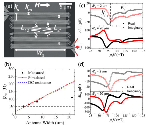 Figure 1
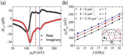 Figure 2
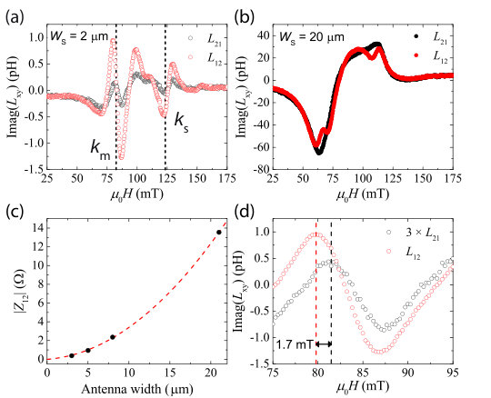 Figure 3
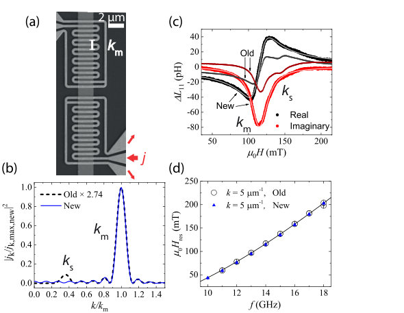 Figure 4
Peer Reviews
No public reviews on file for this paper yet. If you reviewed it on a platform where reviews are public (OpenReview, ICLR, NeurIPS, ICML), you can paste yours below so the community can read it here.
Videos
No videos yet. Explain this paper in a talk, walkthrough, or lecture? Add one.
Optimizing propagating spin wave spectroscopy
Juriaan Lucassen
Department of Applied Physics, Eindhoven University of Technology, 5600 MB Eindhoven, the Netherlands
Casper F. Schippers
Department of Applied Physics, Eindhoven University of Technology, 5600 MB Eindhoven, the Netherlands
Luuk Rutten
Department of Applied Physics, Eindhoven University of Technology, 5600 MB Eindhoven, the Netherlands
Rembert A. Duine
Department of Applied Physics, Eindhoven University of Technology, 5600 MB Eindhoven, the Netherlands
Institute for Theoretical Physics, Utrecht University, Leuvenlaan 4, 3584 CE Utrecht, the Netherlands
Henk J.M. Swagten
Department of Applied Physics, Eindhoven University of Technology, 5600 MB Eindhoven, the Netherlands
Bert Koopmans
Department of Applied Physics, Eindhoven University of Technology, 5600 MB Eindhoven, the Netherlands
Reinoud Lavrijsen
Department of Applied Physics, Eindhoven University of Technology, 5600 MB Eindhoven, the Netherlands
Abstract
The frequency difference between two oppositely propagating spin waves can be used to probe several interesting magnetic properties, such as the Dzyaloshinkii-Moriya interaction (DMI). Propagating spin wave spectroscopy is a technique that is very sensitive to this frequency difference. Here we show several elements that are important to optimize devices for such a measurement. We demonstrate that for wide magnetic strips there is a need for de-embedding. Additionally, for these wide strips there is a large parasitic antenna-antenna coupling that obfuscates any spin wave transmission signal, which is remedied by moving to smaller strips. The conventional antenna design excites spin waves with two different wave vectors. As the magnetic layers become thinner, the resulting resonances move closer together and become very difficult to disentangle. In the last part we therefore propose and verify a new antenna design that excites spin waves with only one wave vector. We suggest to use this antenna design to measure the DMI in thin magnetic layers.
Spin waves can be used to probe fundamental magnetic interactions in a ferromagnet. For example, the uniform spin wave mode is routinely used to determine the magnetic anisotropy in ferromagnetic resonance based techniques. Kittel (1948); Maksymov and Kostylev (2015) More recent advances have demonstrated that spin waves can further be used to probe spin polarized transport Vlaminck and Bailleul (2008); Zhu, Dennis, and McMichael (2010); Sugimoto et al. (2016) and they are also frequently used to quantify the Dzyaloshinkii-Moriya interaction (DMI). Lee et al. (2016); Nembach et al. (2015); Cho et al. (2015); Di et al. (2015) The use of spin waves to measure the DMI is especially interesting, because the field of skyrmionics revolves around this DMI. Fert, Reyren, and Cros (2017) Spin waves are one of the few ways of quantifying this interaction. Ryu et al. (2013); Je et al. (2013); Lee et al. (2016); Nembach et al. (2015); Cho et al. (2015); Di et al. (2015); Han et al. (2016) Measuring the DMI using spin waves utilizes the frequency difference for oppositely propagating spin waves as a direct result of the DMI. Moon et al. (2013); Cortés-Ortuño and Landeros (2013) The most commonly used method to measure this frequency difference is Brillouin light scattering. Nembach et al. (2015); Cho et al. (2015); Di et al. (2015)
Here we focus on the related, though less developed, technique of propagating spin wave spectroscopy (PSWS) Vlaminck and Bailleul (2008) that can also measure the DMI induced frequency difference. Lee et al. (2016); Seki et al. (2016) In PSWS, a micron sized coplanar waveguide is used to electrically generate spin waves with a specific wavevector in a magnetic strip via Oersted fields. These spin waves propagate towards a second antenna, where the spin waves are detected inductively. Although in principle PSWS is very sensitive to frequency differences, the fabrication of the devices is involved, and important details that are critical to correct operation remain underreported.
In this letter we demonstrate that the width of the magnetic strip critically determines the functionality of the device, with narrow strips being optimal. First, we show that correcting for finite length of the microwave contacts (de-embedding) becomes important as the strip width increases. Second, for narrow strips, the spectra show additional resonances that belong to spin wave quantization modes along the strip width. Third, upon increasing the strip width we additionally find that the antenna-antenna coupling also increases, which detrimentally affects the spin wave transmission measurements. Last, we show a new antenna design which is truly monochromatic. This should aid the determination of DMI in magnetic films, as it allows the measurements to be performed for decreased strip thicknesses where the DMI is higher. Moreover, magnonic applications that require the presence of truly monochromatic spin waves can also benefit from this design.
We fabricated devices such as the one displayed in Fig. 1a. The operating principle of such a device is described in detail elsewhere. Vlaminck and Bailleul (2010) In short, as we indicate in red in the figure, we drive a microwave current through one of the antennas. The spatial periodicity of the Oersted fields that couple to the spin waves is determined by the geometry of the antenna. Because there are two main periodicities, indicated by and in the figure, we also excite spin waves with these wave vectors. Spin waves then traverse the strip to the other antenna, where induction allows the spin waves to be detected. The magnetic strip underneath the antenna is fabricated using sputtering and an EBL lift-off process. The sputtered stack is //Ta(4)/Pt(4)/Co(15)/Ir(4)/Pt(4) (thicknesses in parentheses in nm) and was sputter deposited using Ar at mbar on a Si substrate with a native oxide in a system with a base pressure of mbar. On top of the magnetic strip, we deposited 40 nm of Al2O3 using ALD. Finally, the antennas were created using e-beam evaporation of Ti(10)/Au(100) in a second EBL lift-off process. We performed the spin wave resonance measurements using a VNA (Anritsu MS4644B) which we contacted to the antennas using microwave probes. The whole setup was calibrated using a microwave probe calibration substrate. Measurements were performed in field sweep mode with the magnetic field applied transverse to the strip, working in the Damon-Eshbach geometry at a power of [math] dBm. Afterwards, the measured parameters were converted to inductions using well-known microwave relationships. Pozar (2011) Devices were fabricated for various strip widths (2-20 m where the antenna width includes an additional m on each side) and antennas that were designed to excite different wave vectors ( m*-1*).
We start by looking at a typical measurement of the self-induction as shown in Fig. 1c for two different . These measurements correspond to the amplitude of the spin waves that are excited by antenna . We note two different peaks, indicated by the dashed lines, at two different fields which correspond to the two ( and ) wave vectors of spin waves that are excited (later verified by fitting dispersion relation). Additionally, the curves resemble the (anti-)symmetric Lorentzian line shapes typical of ferromagnetic resonance for both strip widths. The phase for m matches what one would expect for magnetic resonance: a symmetric imaginary induction and anti-symmetric real induction. Maksymov and Kostylev (2015) However, the phase of the m device behaves rather differently, where the roles of the real and imaginary parts are now interchanged.
In Fig. 1d we plot the measurements of the self-induction corrected for the small change in the phase of the parameters as a result of the finite distance between the probes and the actual spin wave antenna. This process is called de-embedding. Pozar (2011) For m, there is very little effect of de-embedding. However, for m the phase of the spin wave resonances changes drastically and now matches the m data. This is a rather surprising result because the induced phase difference as a result of the finite distance is only at GHz. Additionally, de-embedding only seems to be important for wider strips. To understand this behaviour, we derive the following relationship (with ) for a 1-port circuit Pozar (2011)
[TABLE]
where is the proper de-embedded self-induction and the measured self-induction. is the non-magnetic part of the impedance of the antenna and is the characteristic impedance of the line (50 ). From this it is clear that de-embedding becomes more important as increases. In Fig. 1b is plotted as a function of antenna width. It increases linearly with the antenna width, which explains why there is much larger effect of de-embedding for larger . This linear increase can be understood very simply in terms of the DC resistance of the antenna which dominates the impedance of the antennas (see supplementary material).
Additionally, we see in Fig. 1c that the magnitude of the induction is only about 5 times larger for m compared to m. The induction should scale linearly with the magnetic volume, which is exactly what is found in Fig. 1d: a 10-fold increase in the induction going from the m strip to the m strip. Once again, this can be understood from eq. (1); there is not only a phase rotation present, but also a multiplicative term proportional to . Although moving to smaller will help decrease and thus remove the need for de-embedding, something similar can be achieved by decreasing the resistance of the antenna. For example, one can increase the thickness of the Au. 111This is no longer useful for thicknesses larger than the skin depth.
Next, we demonstrate that upon decreasing , a spin wave quantization resonance appears in the spectra. To see this more clearly, we plot data for a m strip in Fig. 2a. Once again note that there are two main peaks present in this figure; the peak at mT and the peak at mT, but there is clearly another resonance visible at mT. This resonance vanishes as is increased to m. From this we conclude that any additional periodicities of the antenna geometry that can couple to this spin wave can be excluded, because then it should be present for both and m devices. Vlaminck and Bailleul (2010) Instead, we believe it to be a higher order laterally quantized spin wave mode (inset Fig. 2b), which to our knowledge has not yet been reported in PSWS measurements.
A more detailed quantitative analysis can be performed by fitting the dispersion relation to the resonance fields . We obtain these by fitting the spectrum of Fig. 2a to a combination of symmetric and anti-symmetric Lorentzian lineshapes. 222We use 4 symmetric- and anti-symmetric Lorenzians to fit the curves. We need a fourth curve to properly fit the background for some measurements. We believe there to be a fourth spin wave resonance - the quantization of the peak - at higher fields, but we are not able to reliable fit this peak. The resulting are indicated by the vertical dashed lines. For all three resonances, is plotted in Fig. 2b as a function of the frequency .
These curves are fitted simultaneously using dispersion relations derived elsewhere Kalinikos (1981); Kalinikos and Slavin (1986) which are also plotted in Fig. 2b. Here, we use , MA m*-1* and m*-1* (fixed by the antenna geometry). We assume that the quantized spin wave mode is an mode (mode profiles are indicated in the inset of Fig. 2b) because the excitation efficiency for the mode is negligible. Kittel (1958) The quantization is taken into account by adding a wavevector perpendicular to the propagation direction in the dispersion relation. Guslienko et al. (2002) We use the following fit parameters: an effective strip width , layer thickness and , with the magnetic anisotropy field. The resulting fit gives MA m*-1*, m, and nm. is reasonable for this system. Lee et al. (2016) Because we do not take into account the non-uniform internal dipolar fields, Guslienko et al. (2002); Guslienko, Chantrell, and Slavin (2003) the underestimation of and is not surprising. In the supplementary material we present fits for devices with different values.
We now turn our attention to the spin wave transmission measurements. A typical measurement for m is plotted in Fig. 3a, where we plot the mutual induction () which corresponds to spin waves traveling from antenna 2 (1) to 1 (2) (see Fig. 1a). Once again, we can distinguish two peaks corresponding to the two different type of spin waves that are excited. Note two very distinct features that are indicative of a proper electrical spin wave transmission signal: first, a distinct amplitude asymmetry between oppositely traveling spin waves ( vs ), which is the result of the chirality of the driving fields that matches the corresponding spin wave () or opposes it (). Schneider et al. (2008) Second, sharp oscillations of the spin wave transmission signal which are the result of a variation in the spin wave phase as we sweep through the resonance. Vlaminck and Bailleul (2010)
However, a similar measurement for m yields Fig. 3b. Both the amplitude asymmetry and the sharp oscillations now no longer seem present. This is rather surprising, as both features have an origin that does not depend on . Rather, we believe it is related to a direct parasitic coupling between the two antennas. This means that if a spin wave is excited by antenna 1 there is a signal induced in antenna 2 independent of an actual physical spin wave being transmitted. 333A simple way to check this would entail removing the magnetic strip between the antennas only. However, as detailed in the supplementary material, this parasitic coupling is also mediated by the magnetic strip. Therefore, it still remains to be explicitly verified that the parasitic coupling is independent of spin waves being transmitted. For example, for there is still a small oscillatory signal superimposed on the large resonant background. This background is the result of the parasitic coupling and the small superimposed signal is the transmitted spin wave. The spin wave transmission signal for is smaller, as observed in Fig. 3a, such that the smaller oscillatory signal on top of this induction is no longer visible in Fig. 3b.
The magnitude of the parasitic coupling is plotted in Fig. 3c, where we find that the coupling seems to scale quadratically with the antenna width. This explains why devices with smaller do show a proper spin wave transmission signal. Yet, even for small this parasitic coupling can become problematic at higher frequencies where the increasing spin wave attenuation decreases the spin wave transmission signal. 444Moving the antennas closer together should remedy (at least part of) this issue At present, we cannot explain the size and behaviour of this coupling, but more details can be found in the supplementary material.
For the m device a peak shift can be extracted that could be a measure for the DMI. This shift is shown in Fig. 4d, where is shifted about mT with respect to . The shift is opposite to the direction expected from DMI [assuming pJ m*-1* (Ref. Han et al., 2016)], which is about mT. This shift can have other contributions beyond the DMI, such as the anisotropy difference induced shift. Gladii et al. (2017) Upon moving to thinner layers, this contribution should decrease in size, and the contribution of the DMI to the field shift will increase. Therefore, in future work, we would like to investigate thinner layers to determine the origin of this shift.
In the final part of this letter, we a present a new antenna design. This has the major advantage of exciting only one type spin wave () which is necessary if thinner layers have to be investigated. Upon decreasing the layer thickness the two traditional spin wave resonances (corresponding to and ) start overlapping because the interfacial anisotropy term becomes more important and because of the decreasing influence of the magnetostatic interactions. Although the ratio between the and resonance is quite large for , they are of approximately equal size in the transmission measurement as seen in Fig. 3a. If the two peaks move closer together, disentangling the two resonances becomes increasingly difficult in a transmission measurement.
The new antenna design is shown in Fig. 4a. Rather than relying on a conventional CPW signal and ground line structure, in this new design only the signal line is meandered. There is no need to adhere to conventional coplanar waveguide structures for these spin wave antennas as the antennas are much smaller than the electrical wavelength. In the figure we indicate the only periodicity present such that spin waves with only one wave vector are excited. This should negate the problem of overlapping spin wave resonances in the transmission induction spectra. To further illustrate how this works, note that in Ref. Vlaminck and Bailleul, 2010 it is demonstrated that the spin wave excitation signals are proportional to the square of the spatial Fourier transform of the current density used to excite the spin waves. In Fig. 4b the Fourier transform of the current density for both the old (Fig. 1a) and new (Fig. 4a) antenna design are plotted. For the old design, there are two peaks ( and ) that correspond to the two spin wave resonances that are measured. For the new design, however, the secondary peak at disappears, meaning that with this new design spin waves with only one wave vector are excited. Moreover, the peak of the new design is times larger than the old design as a result of the higher current density that flows through the new design, suggesting the induction signals should also be larger.
We verify these predictions by measuring the self-induction for the new antenna design; this is plotted in Fig. 4c together with a similar measurement on a device with the old antenna design. As can be seen, the secondary peak at has vanished for the new antenna design, agreeing with our initial expectations based on the periodicity of the antenna. The intensity of the signal is also a factor larger which agrees mostly with the initial predictions based on the current density.
A more thorough analysis is obtained by fitting the spectra to obtain the resonance fields . Such a fit is also displayed in Fig. 4c with solid lines. 555 We use only 1 symmetric and anti-symmetric Lorentzian to fit the spectrum. The higher order mode for the new design is not fitted. It is visible but the fits consistently placed the peak at a different location. Combining this with a dispersion relation analysis similar to the one performed in Fig. 2b yields Fig. 4d, where we plot only the main resonance field of the spectra. The resonance fields for the new design, shown in blue, lay perfectly on top of the data of the old design. fit
To summarize, we have demonstrated the benefit of using narrower strips for propagating spin wave spectroscopy (PSWS). We ended the letter with a demonstration of a new antenna design that allowed us to excite spin waves with only one wave vector suitable for the investigation of DMI in thinner films.
See supplementary materials for (1) details on the COMSOL™ simulations, (2) additional information, (3) a full dispersion relation fit and (4) additional details on the parasitic coupling .
This work is part of the research programme of the Foundation for Fundamental Research on Matter (FOM), which is part of the Netherlands Organisation for Scientific Research (NWO).
The reference list from the paper itself. Each links out to its DOI / PubMed record.
- 1Kittel (1948) C. Kittel, Phys. Rev. 73 , 155 (1948) . · doi ↗
- 2Maksymov and Kostylev (2015) I. S. Maksymov and M. Kostylev, Physica E: Low-dimensional Systems and Nanostructures 69 , 253 (2015) . · doi ↗
- 3Vlaminck and Bailleul (2008) V. Vlaminck and M. Bailleul, Science 322 , 410 (2008) . · doi ↗
- 4Zhu, Dennis, and Mc Michael (2010) M. Zhu, C. L. Dennis, and R. D. Mc Michael, Phys. Rev. B 81 , 140407 (2010) . · doi ↗
- 5Sugimoto et al. (2016) S. Sugimoto, M. C. Rosamond, E. H. Linfield, and C. H. Marrows, Applied Physics Letters 109 , 112405 (2016) . · doi ↗
- 6Lee et al. (2016) J. M. Lee, C. Jang, B.-C. Min, S.-W. Lee, K.-J. Lee, and J. Chang, Nano Letters 16 , 62 (2016) . · doi ↗
- 7Nembach et al. (2015) H. T. Nembach, J. M. Shaw, M. Weiler, E. Jué, and T. J. Silva, Nature Physics 11 , 825 EP (2015) . · doi ↗
- 8Cho et al. (2015) J. Cho, N.-H. Kim, S. Lee, J.-S. Kim, R. Lavrijsen, A. Solignac, Y. Yin, D.-S. Han, N. J. J. van Hoof, H. J. M. Swagten, B. Koopmans, and C.-Y. You, Nature Communications 6 , 7635 EP (2015) . · doi ↗