Negative optical torque on a microsphere in optical tweezers
K. Diniz, R. S. Dutra, L. B. Pires, N. B. Viana, H. M. Nussenzveig and, P. A. Maia Neto

TL;DR
This paper demonstrates that optical tweezers with elliptically polarized beams can exert a negative optical torque on microspheres, with the effect observable across various particle sizes and configurations, enabling new characterization methods.
Contribution
It introduces a method to observe and analyze negative optical torque in optical tweezers, accounting for astigmatism, and proposes using microsphere rotation measurements for system characterization.
Findings
Confirmed negative optical torque across multiple particle sizes.
Achieved agreement with theoretical predictions without fitting.
Proposed a new method for characterizing trapping parameters.
Abstract
We show that the optical force field in optical tweezers with elliptically polarized beams has the opposite handedness for a wide range of particle sizes and for the most common configurations. Our method is based on the direct observation of the particle equilibrium position under the effect of a transverse Stokes drag force, and its rotation around the optical axis by the mechanical effect of the optical torque. We find overall agreement with theory, with no fitting, provided that astigmatism, which is characterized separately, is included in the theoretical description. Our work opens the way for characterization of the trapping parameters, such as the microsphere complex refractive index and the astigmatism of the optical system, from measurements of the microsphere rotation angle.
Click any figure to enlarge with its caption.
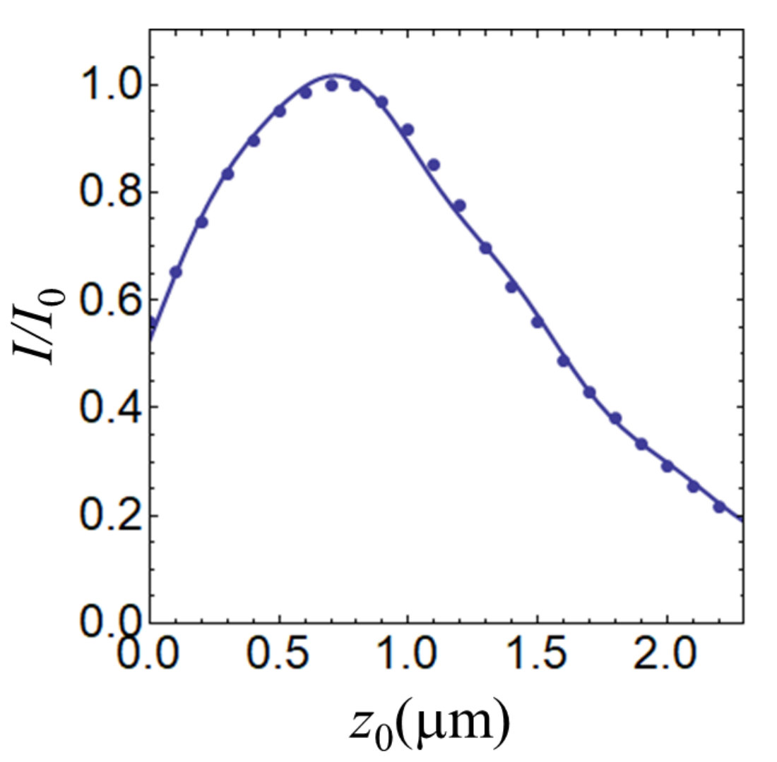 Figure 1
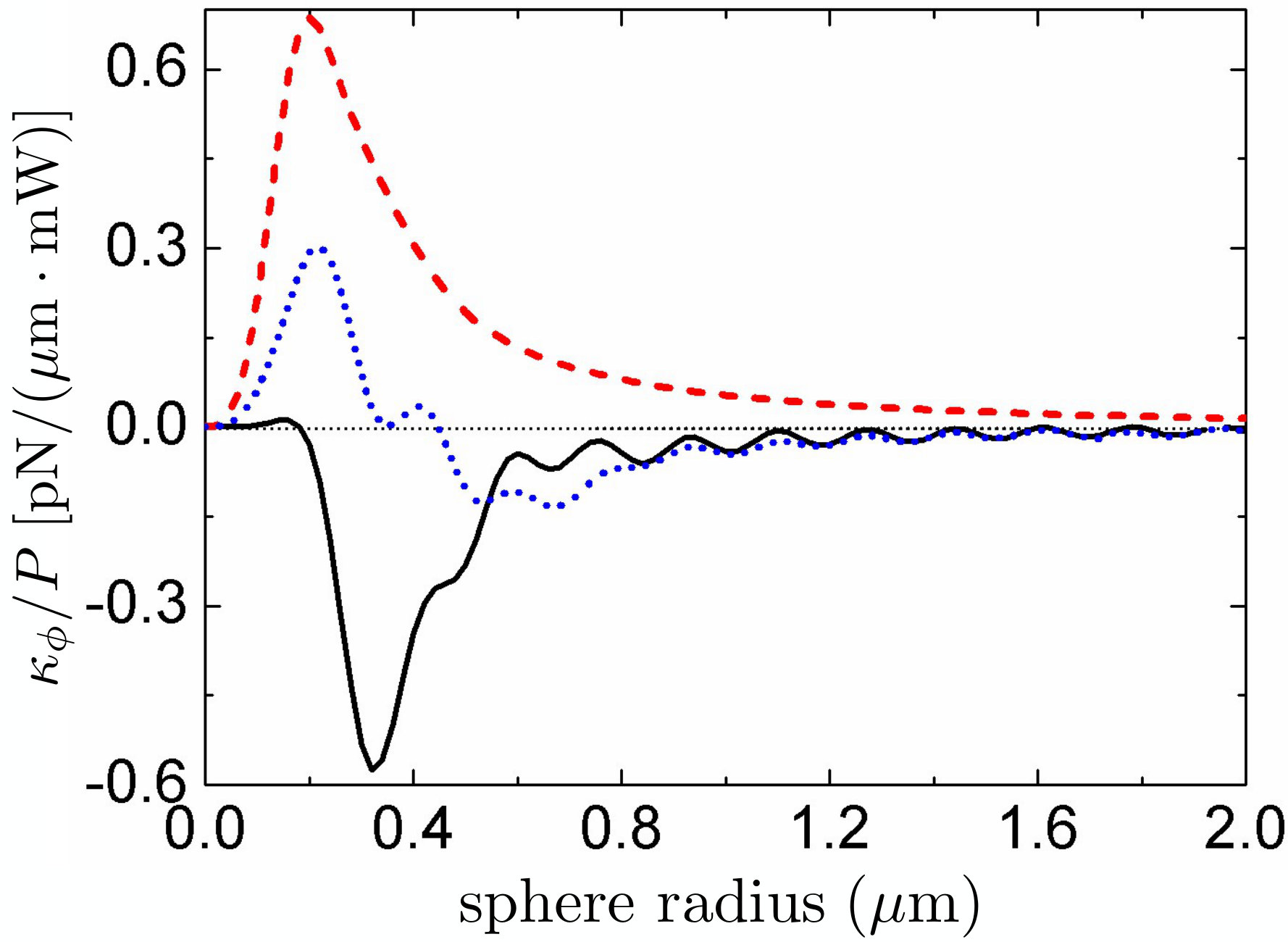 Figure 2
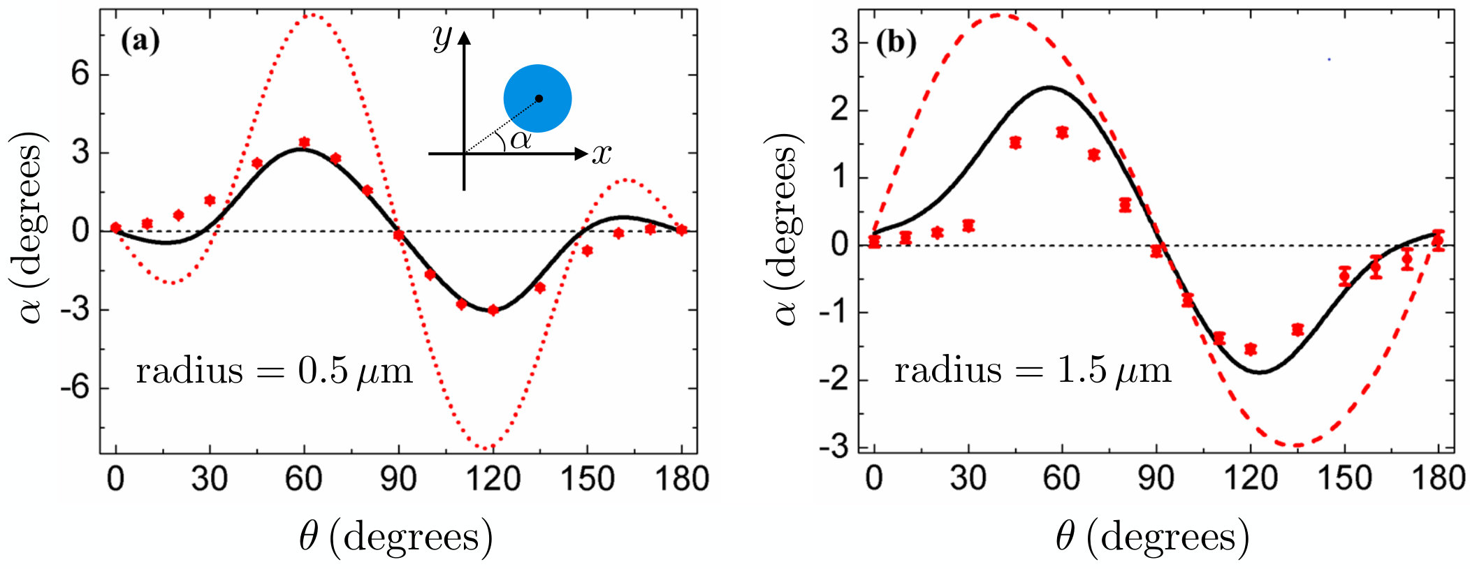 Figure 3
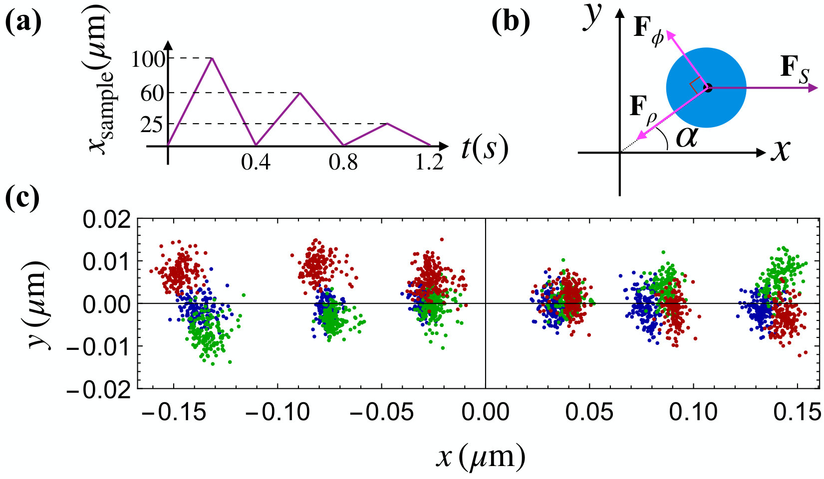 Figure 4
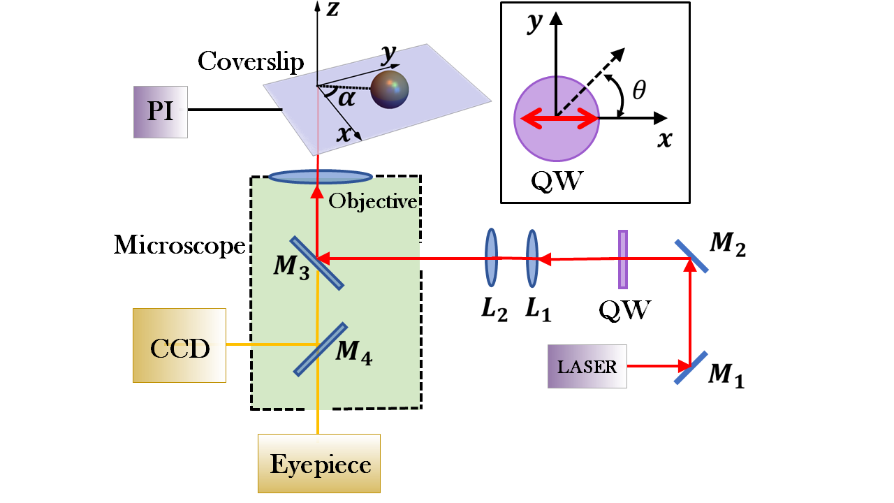 Figure 5
Peer Reviews
No public reviews on file for this paper yet. If you reviewed it on a platform where reviews are public (OpenReview, ICLR, NeurIPS, ICML), you can paste yours below so the community can read it here.
Videos
No videos yet. Explain this paper in a talk, walkthrough, or lecture? Add one.
Negative optical torque on a microsphere in optical tweezers
K. Diniz
Instituto de Física, Universidade Federal do Rio de Janeiro, CP 68528, Rio de Janeiro RJ 21941-909, Brazil
LPO-COPEA, Instituto de Ciências Biomédicas, Universidade Federal do Rio de Janeiro, Rio de Janeiro, RJ, 21941-590, Brasil
R. S. Dutra
LISComp-IFRJ, Instituto Federal de Educação, Ciência e Tecnologia, Rua Sebastião de Lacerda, Paracambi, RJ, 26600-000, Brasil
L. B. Pires
Instituto de Física, Universidade Federal do Rio de Janeiro, CP 68528, Rio de Janeiro RJ 21941-909, Brazil
LPO-COPEA, Instituto de Ciências Biomédicas, Universidade Federal do Rio de Janeiro, Rio de Janeiro, RJ, 21941-590, Brasil
N. B. Viana
Instituto de Física, Universidade Federal do Rio de Janeiro, CP 68528, Rio de Janeiro RJ 21941-909, Brazil
LPO-COPEA, Instituto de Ciências Biomédicas, Universidade Federal do Rio de Janeiro, Rio de Janeiro, RJ, 21941-590, Brasil
CENABIO - Centro Nacional de Biologia Estrutural e Bioimagem, Universidade Federal do Rio de Janeiro, Rio de Janeiro, RJ, 21941-902, Brasil.
H. M. Nussenzveig
Instituto de Física, Universidade Federal do Rio de Janeiro, CP 68528, Rio de Janeiro RJ 21941-909, Brazil
LPO-COPEA, Instituto de Ciências Biomédicas, Universidade Federal do Rio de Janeiro, Rio de Janeiro, RJ, 21941-590, Brasil
CENABIO - Centro Nacional de Biologia Estrutural e Bioimagem, Universidade Federal do Rio de Janeiro, Rio de Janeiro, RJ, 21941-902, Brasil.
P. A. Maia Neto
Instituto de Física, Universidade Federal do Rio de Janeiro, CP 68528, Rio de Janeiro RJ 21941-909, Brazil
LPO-COPEA, Instituto de Ciências Biomédicas, Universidade Federal do Rio de Janeiro, Rio de Janeiro, RJ, 21941-590, Brasil
CENABIO - Centro Nacional de Biologia Estrutural e Bioimagem, Universidade Federal do Rio de Janeiro, Rio de Janeiro, RJ, 21941-902, Brasil.
Abstract
We show that the optical force field in optical tweezers with elliptically polarized beams has the opposite handedness for a wide range of particle sizes and for the most common configurations. Our method is based on the direct observation of the particle equilibrium position under the effect of a transverse Stokes drag force, and its rotation around the optical axis by the mechanical effect of the optical torque. We find overall agreement with theory, with no fitting, provided that astigmatism, which is characterized separately, is included in the theoretical description. Our work opens the way for characterization of the trapping parameters, such as the microsphere complex refractive index and the astigmatism of the optical system, from measurements of the microsphere rotation angle.
I Introduction
Negative optical forces are at the origin of single-beam optical traps Ashkin et al. (1986), also known as optical tweezers, which have become extremely important tools in several fields of physics Ashkin (2006) and cell biology Fazal and Block (2011). The optical torque (OT) on a transparent and isotropic microsphere at its equilibrium position vanishes Marston and Crichton (1984); Barton et al. (1989), since Mie scattering conserves optical angular momentum (AM) when the microsphere is aligned along the beam symmetry axis Schwartz and Dogariu (2006). However, if the microsphere is displaced laterally, optical AM might be transferred to the microsphere center of mass Ruffner and Grier (2012).
In this paper, we show, both theoretically and experimentally, that the resulting orbital optical torque (OT) points along the direction opposite to the incident field AM in most situations involving practical applications of optical tweezers with circularly or elliptically polarized Gaussian trapping beams.
Negative or left-handed OT is analogous to the negative optical force in single-beam traps. An oblate spheroid was predicted to spin around the axis of a circularly polarized Gaussian beam with the opposite handedness of the incident optical AM Simpson and Hanna (2007). Additional proposals for implementation include the employment of chiral media Canaguier-Durand and Genet (2015); Li et al. (2017) and particle arrays with discrete rotational symmetry Chen et al. (2014). A negative OT was theoretically predicted for a small isotropic particle illuminated by a vortex beam in the Rayleigh scattering approximation Nieto-Vesperinas (2015). Reverse orbiting of non-spherical particles confined on a 2D interface was observed by employing Laguerre-Gaussian vortex beams Jesacher et al. (2006). Negative OT was demonstrated for a macroscopic inhomogenous and anisotropic disk by measuring the rotationally Doppler-shifted reflected light Hakobyan and Brasselet (2014, 2015) and more recently by the direct observation of the disk rotation Magallanes and Brasselet (2018).
A pioneering paper Friese et al. (1998) demonstrated positive OT on optically trapped birefringent particles by elliptically polarized light. An extension to isotropic transparent nonspherical particles was reported in Bishop et al. (2003). Important applications to cell biology are reviewed in Forth et al. (2013). Conversion from optical spin AM to mechanical orbital AM has been demonstrated by focusing a Gaussian beam with circular polarization Zhao et al. (2009). Positive or negative OT was observed depending on the configuration of an array of particles Adachi et al. (2007); Sule et al. (2017); Han et al. (2018). The optical force field is non-conservative on account of the azimuthal force component responsible for the OT and the resulting Brownian motion is a rich platform for investigating non-equilibrium effects Ruffner and Grier (2012); Svak et al. (2018).
Here we measure the mechanical effect of the OT by monitoring the microsphere equilibrium position laterally displaced by an external Stokes drag force, as a function of the helicity of the elliptically polarized trapping beam. Since the particle is displaced off-axis, an OT appears, and as a consequence the equilibrium position is rotated around the beam axis. Our experimental and theoretical results indicate that the OT turns out to be negative in most cases of practical interest provided that the trapping beam is not very astigmatic.
II Experimental procedure
Fig. 1 is a diagram of our experimental setup. A laser beam (IPG photonics, model YLR-5-1064LP) with wavelength , linearly polarized along the direction, goes through a quarter waveplate (QW) after reflection by mirrors and that are employed to control the beam position. The fast axis of the QW makes an angle with the direction and the beam propagates along the positive direction. The laser beam is then directed to a beam expander, consisting of lens with focal distance and lens with focal distance . The expanded beam, with waist is reflected by a dichroic mirror () and directed to the entrance of a Nikon PLAN APO, 100x, NA = 1.4, oil-immersion objective with back aperture radius , of a Nikon TI-U infinity-corrected inverted microscope. The total objective transmittance Viana et al. (2006a), including the apodization loss due to overfilling the objective back aperture, is The beam is focused onto a sample chamber topped by an O-ring, placed on a coverslip, containing a water suspension of polystyrene microspheres. Control of the microsphere height is critical for comparison with theory because of the spherical aberration introduced by refraction at the glass-water interface Török et al. (1995). We follow the procedure of Viana et al. (2006b, 2007). We first move the objective down until the trapped microsphere touches the coverslip. Starting from this configuration, we then displace the objective upwards by distances and when trapping microspheres of radii and respectively. The laser beam power at the objective entrance port was for the smaller sphere and for the larger one.
In order to displace the microsphere off-axis and produce an OT, the sample is alternately driven along positive and negative directions by a piezoelectric nano-positioning stage (Digital Piezo Controller E-710, Physik Instrumente). Three different speeds are employed: and defining the cycle shown in Fig. 2(a) that is repeated over time. Images of the entire process are recorded by a CMOS camera (Hamamatsu Orca-Flash2.8 C11440-10C) for data analysis.
The resulting Stokes drag force displaces the trapped microsphere off-axis. Since the trapping beam transfers AM to the sphere, its equilibrium position gets displaced to a direction on the plane rotated around the axis by an angle with respect to the axis, as depicted in Fig. 2(b). In Fig. 2(c), we show experimental data for the microsphere position on the plane, for a microsphere of radius and (blue), (green) and (red). Points corresponding to a given sample speed appear to be lumped together as expected. We measure from a linear fit of all points corresponding to a given (the transverse stiffness can also be obtained and the results are compatible with theoretical MDSA+ values Dutra et al. (2012, 2014)). We intentionally rotate the camera by with respect to the axes of the microscope stage so as to have comparable displacements along and axes. We then determine an offset for representing the angle of rotation of the camera with respect to the direction of the sample displacement, by taking the average of the values found for and (linear polarization), which are measured twice as often as for the other values of corresponding to non-zero helicities. The axes shown in Fig. 2(c) were rotated accordingly.
The optical force balancing the Stokes force has radial and azimuthal cylindrical components and with accounting for the OT, as illustrated in Fig. 2(b). The rotation angle is given by We compare the experimental results for the rotation angle with theoretical results for the optical force components. The ratio between the cylindrical optical force components is calculated with the help of the Mie-Debye spherical aberration (MDSA) theory of optical tweezers Viana et al. (2007), either with (MDSA+) Dutra et al. (2012, 2014) or without the inclusion of astigmatism, as discussed in the next section.
III MDSA theory
The Mie-Debye theory of optical tweezers Maia Neto and Nussenzveig (2000); Mazolli et al. (2003) relies on the electromagnetic generalization of Debye’s scalar model for a diffraction-limited focused optical beam derived by Richards and Wolf Richards and Wolf (1959). The focused laser beam incident on the microsphere is decomposed into an angular spectrum of plane waves and the results are valid well beyond the validity range of the paraxial approximation. The standard Mie scattering results are adapted for a general direction of incidence by developing the multipolar expansion of a plane wave propagating along an arbitrary direction with the help of the Wigner rotation matrix elements. The scattered field is then obtained as a superposition of the contributions from all plane-wave components of the non-paraxial focused beam. The optical force on the sphere is finally obtained by integrating the Maxwell stress tensor over a spherical surface at infinity.
Within MDSA, the model for the nonparaxial focused beam is built from the expression for the paraxial beam at the objective entrance port, taking into account the spherical aberration introduced by refraction at the planar interface between the glass slide and sample aqueous solution. We assume the laser beam at the entrance port to be Gaussian with a planar wavefront. The elliptical polarization at the entrance port is defined by the angle between the fast axis of QW and the original linear polarization direction along the axis, as depicted in the inset of Fig. 1:
[TABLE]
where is electric field amplitude at the center of the objective entrance port and are the unit vectors for right-handed () and left-handed () circular polarizations, which are obtained by taking the fast axis at and respectively.
The multipole expansion of the focused beam, which plays the role of the incident field on the microsphere, is simpler for circular polarization. A general polarization state can be readily obtained by writing the incident field as a superposition of and circular polarizations, as illustrated by Eq. (1) for the elliptical polarization produced by QW (see also Dutra et al. (2007) for a detailed derivation for linear polarization). Since the Maxwell stress tensor is quadratic in the electric and magnetic fields, contains cross terms in addition to the result for circular polarization. For the elliptical polarization (1), the azimuthal force component when the sphere center is at position is given by
[TABLE]
The first term on the right-hand-side of (2) accounts for the transfer of spin AM to the microsphere center-of-mass, and is the azimuthal force component when taking circular polarization (). Its explicit partial-wave expansion is given in Viana et al. (2007). The transfer of AM is modulated by the optical helicity and is simply reversed when replacing as expected. In the particular case of circular polarization, the focused spot is rotationally symmetric around the axis and all cylindrical force components are independent of
On the other hand, when the polarization at the entrance port is elliptical, the non-paraxial focal spot (electric energy density map) is elongated along the major axis of the polarization ellipse (a similar effect is discussed in Richards and Wolf (1959) for linear polarization). In our case, the ellipse principal axes lie along the directions and defined by QW, and as a consequence the gradient of the electric energy density contains an azimuthal component depending on in addition to the usual radial one. Thus, the gradient is radial only along the directions of the major axes: with integer. Although the optical force is not in general proportional to the gradient of the electric energy density (due to the contribution of higher multipoles in addition to the electric dipole one), the same symmetry properties of the optical force field still hold as in the Rayleigh limit. Thus, the nonparaxial spot elongation is the source of the second term on the r.-h.-s. of (2), which indeed vanishes for and in the case of circular polarization. More specifically, results from the cross contribution obtained when computing the optical force from the Maxwell stress tensor as discussed previously. Its explicit partial-wave expansion is given in Appendix A.
IV Results
We start with the theoretical results derived within MDSA and MDSA+ for the parameters and conditions corresponding to our experiment. As shown in Fig. 2(c), they correspond to small off-axis displacements, allowing us to approximate in terms of the torsion constant, defined as Note that the orbital OT vanishes when the sphere center is aligned along the beam symmetry axis (). On the other hand, even in this case AM may still be transferred and lead to spinning of absorbing spheres, which is outside our current experimental reach. Therefore, it is not considered in this paper. In Fig. 3, we plot the variation of (in units of the laser beam power in the sample region) with the microsphere radius , at the focal plane for left-handed () circular polarization at the objective entrance port.
In all three examples shown in Fig. 3, we have taken for the real part of the microsphere refractive index, corresponding to polystyrene at Ma et al. (2003). The dashed and solid lines represent the results of MDSA theory, which neglects optical aberrations other than the spherical aberration introduced by refraction at the glass slide planar interface. We assume the paraxial focal plane to be at a distance from the glass slide.
When the imaginary part of the refractive index is sufficiently large, we expect to be positive for all microsphere radii, since the positive optical AM is then transferred to the microsphere by absorption. We illustrate this case by taking (dashed line). On the other hand, for polystyrene, with Ma et al. (2003), scattering dominates over absorption, and the OT has the sign opposite to the input spin AM for most of the range of radii shown in Fig. 3 (solid line). We conclude that the scattered field carries AM in excess of the incident trapping beam AM in such cases, thus leading to a negative OT.
For small spheres in the Rayleigh limit, the OT is dominated by extinction rather than by the angular momentum transfer to the scattered field, so that the OT is positive, as shown in Fig. 3. Thus, small microspheres behave as local probes of the incident beam AM, producing negligible scattering. As a consequence, the OT has the same handedness as the laser beam at the objective entrance port.
In the opposite range of large spheres, the geometrical optics result is recovered as an average over wave-optical interference oscillations Mazolli et al. (2003). Such oscillations are suppressed when absorption is large (dashed line), but are clearly visible in the case of polystyrene (solid line). For transparent spheres, the OT vanishes in the geometrical optics limit (see Appendix E of Mazolli et al. (2003)), so that the OT oscillates between positive and negative values. At the crossover between the Rayleigh and geometrical optics ranges, the OT develops a remarkable negative peak for transparent materials (solid line).
As found for the transverse trap stiffness such peak is severely modified by optical aberrations additional to the spherical aberration already taken into account in MDSA theory. Indeed, the astigmatism introduced by small misalignments in the experimental setup typically degrades the focal region thus leading to a reduction of Roichman et al. (2006); Dutra et al. (2012, 2014) in the peak region, located at the crossover between the Rayleigh and geometrical optics regions. The effect of astigmatism on ( axis angular position) is shown by the dotted curve in Fig. 3. We have employed MDSA+ theory with the Zernike amplitude obtained by measurements of the reflected focal spot Dutra et al. (2014), as detailed in Appendix B. Explicit expressions for the optical force within MDSA+ are given in Appendix C.
Fig. 3 shows that even a small amount of astigmatism not only suppresses the negative peak found in the ideal MDSA case, but also changes the sign of from negative to positive (and hence with the same handedness as the spin AM at the objective entrance port) on the lower side of the peak region, thereby extending the positive Rayleigh region to larger values of radius. Thus, a practical implementation of the OT reversal with polystyrene microspheres requires astigmatism to be sufficiently small, and microsphere radii in the range We have measured the rotation angle produced by the OT for two sphere sizes in this range.
In Fig. 4, we plot versus the QW angle Since the off-axis displacements and the rotation angles are small, we can approximate When computing from Eq. (2), we take since the Stokes force is applied along the direction. Within MDSA+, a more involved expression is used (see Supplement 1). Because of spherical aberration, the theoretical predictions depend of the focal height from the glass slide. We first find the focal height leading to an equilibrium position such that the microsphere is touching the glass slide. Then, we add the height corresponding to the objective upward displacement in order to mimic the experimental procedure Dutra et al. (2014). Fig. 4a shows experimental results for a microsphere of radius together with the theoretical curves based either on MDSA (dotted line) or MDSA+ (solid line) with the aforementioned astigmatism amplitude and measured for our setup. According to Eq. (2), the theoretical curves deviate from a pure sinusoidal function proportional to which is directly associated to the transfer of spin AM to the microsphere, because of the cross term associated to the focal spot asymmetry, which is proportional to The relative contribution of the spot asymmetry is smaller when astigmatism is taken into account, as expected since optical aberrations degrade the focal region and thus tend to average out the energy density distribution.
We find overall good agreement with MDSA+ theory, with no fitting parameters. The residual disagreement with the experimental data shown in Fig. 4(a) indicates that our theory slightly overestimates the spot asymmetry effect, so that the experimental curve is closer to a pure sinusoidal function proportional to than the MDSA+ one. In particular, the latter predicts a (small) rotation with the same handedness as the elliptical polarization for and However, the experimental data display a rotation opposite to the polarization handedness (given by the sign of ) for all measured values of
In Fig. 4(b), both theoretical curves are calculated with MDSA+ for the microsphere radius In addition to the solid line corresponding to polystyrene, we also show the result for zero absorption (dashed). Although the sphere diameter is much smaller than the attenuation length for polystyrene, Fig. 4(b) shows that absorption has a significant effect on the rotation angle (while it is irrelevant for the microsphere). As expected, absorption tends to decrease the OT reversal. When compared to experimental data, the theoretical prediction based on the value reported by Ma et al. (2003) slightly overestimates the magnitude of
V Conclusion
In conclusion, we have demonstrated a negative OT on trapped polystyrene microspheres by measuring the rotation of the particle equilibrium position under the effect of a Stokes drag force. Good agreement was found between our experimental data and MDSA+ theoretical predictions for the rotation angle, with no fitting. Our method could be applied to characterize the absorption of the trapped sphere material, a property difficult to access experimentally, as well as the degree of astigmatism present in the optical setup, given that the microsphere rotation angle is very sensitive to those parameters.
The negative OT can be seen as an example of spin-orbit interaction (see Bliokh et al. (2015) for a recent review). Our experiment indeed involves two well-known mechanisms for spin-orbit coupling: nonparaxial focusing Zhao et al. (2007); Monteiro et al. (2009) and scattering Bliokh et al. (2011). However, there is an important distinction between these two effects. Whereas focusing conserves the total optical AM Monteiro et al. (2009); Bliokh et al. (2011), scattering by the microsphere laterally displaced with respect to the beam symmetry axis generates the optical AM excess which is responsible for the negative OT on the sphere center-of-mass. Since the scattered spin AM cannot be further enhanced with respect to the spin AM of our circularly-polarized paraxial Gaussian beam at the the objective entrance port, the excess AM is necessarily orbital.
As a perspective for future work, employing Laguerre-Gauss vortex beams at the objective entrance port might open the way for a richer environment, where incident orbital and spin AM would be simultaneously set to play. Moreover, employing a laser beam with a larger AM per photon might enhance the magnitude of the negative OT.
We are grateful to Y. A. Ayala, D. S. Ether Jr, P. B. Monteiro and B. Pontes for discussions.
Funding. National Council for Scientific and Technological Development (CNPq); Coordination for the Improvement of Higher Education Personnel (CAPES); National Institute of Science and Technology Complex Fluids (INCT-FCx); and Research Foundations of the States of Minas Gerais (FAPEMIG), Rio de Janeiro (FAPERJ) and São Paulo (FAPESP) (2014/50983-3).
Appendix A MDSA theory of the optical force in optical tweezers
We first define the dimensionless efficiency factor Ashkin (1992)
[TABLE]
where is the optical force at position in cylindrical coordinates, is the laser beam power at the sample region, is the refractive index of the immersion fluid (water in our setup) and is the speed of light. The position of the microsphere center (in cylindrical coordinates) is measured with respect to the paraxial focus.
There are two separate contributions to the efficiency factor:
[TABLE]
is the rate of momentum removal from the incident trapping beam, whereas represents the rate of momentum transfer to the scattered field.
We compute the efficiency factor for the elliptical polarization produced by a quarter-wave plate whose fast axis makes an angle with the direction of linear polarization of the incident laser beam. The azimuthal component of contains a term proportional to the helicity
[TABLE]
and a second term associated to the spot asymmetry when the polarization is not circular:
[TABLE]
corresponds to circularly-polarized trapping beams. Its partial-wave expansion is given in Viana et al. (2007).
As in the case of linear polarization Dutra et al. (2007), the second term in the r.-h.-s. of (6) results from the cross contribution that appears when the polarization is not circular. Following (4), we write The scattering contribution is given by
[TABLE]
[TABLE]
The extinction term is written as
[TABLE]
The fraction of power transmitted into the sample chamber is given by
[TABLE]
with and ( refractive index of the glass slide). The parameter is the ratio between the objective focal length and the beam waist at the entrance aperture of the objective. The Mie coefficients and represent the scattering amplitudes for electric and magnetic multipoles, respectively Bohren and Huffman (1983).
The multipole coefficients appearing in (7) are given by:
[TABLE]
with and are the Wigner finite rotation matrix elements Edmonds (1957) evaluated at the angle in the immersion fluid and are the cylindrical Bessel functions Watson (1966). Refraction at the interface between the glass slide and the immersion fluid introduces the Fresnel transmission amplitude
[TABLE]
and the spherical aberration phase Török et al. (1995) ( height of paraxial focus with respect to the glass slide)
[TABLE]
The extinction contribution (8) is written in terms of the coefficients
[TABLE]
Appendix B Characterization of Primary Astigmatism
Small misalignments in our optical system introduce astigmatism into the trapping beam. As a consequence, the focused beam angular spectrum contains a Zernike phase Born and Wolf (1959)
[TABLE]
We characterize the amplitude and the axis angular position in our setup by employing the method described in Dutra et al. (2014). We replace our sample by a mirror that reflects the laser beam back towards the objective. The laser spot image is conjugated by the microscope tube lens onto a a CMOS camera (Hamamatsu Orca-Flash2.8 C11440-10C) for data analysis. We employ the piezoelectric nanopositioning system PI (Digital Piezo Controller E-710, Physik Instrumente, Germany) to move the mirror across the focal region with controlled velocity
The spot changes as a function of the mirror position is defined as the angle between the spot major axis and the axis when the mirror is placed at the tangential focus. We also measure the value of by considering the direction of the major axis when the mirror is placed at the sagittal focus. We have analyzed five images at each focus and found
To determine the astigmatism amplitude we fit (least square method) the light intensity at the center of the spot as function of as shown in Fig. 5. The theoretical curve is obtained from the nonparaxial propagation through the optical system Novotny et al. (2001) as described in detail elsewhere Dutra et al. (2014). We find
Appendix C MDSA+ theory
Once the astigmatism parameters are characterized (see previous section), we are able to compute the optical force by generalizing MDSA theory in order to take such primary aberration into account (MDSA+) Dutra et al. (2014). Since the astigmatism phase (14) is not rotationally symmetric around the axis, Eq. (6) no longer holds, and the optical force field has a more complex dependence on the microsphere angular coordinate
Explicit expressions for the cylindrical components are given below. The microsphere position is now measured with respect to the diffraction focus. We employ the notation
[TABLE]
Scattering force
[TABLE]
[TABLE]
[TABLE]
[TABLE]
[TABLE]
[TABLE]
[TABLE]
[TABLE]
[TABLE]
[TABLE]
[TABLE]
[TABLE]
Extinction force
[TABLE]
[TABLE]
[TABLE]
[TABLE]
[TABLE]
Multipole coefficients
[TABLE]
[TABLE]
[TABLE]
For astigmatic beams, the multipole coefficients written above contain an additional series involving cylindrical Bessel functions:
[TABLE]
The reference list from the paper itself. Each links out to its DOI / PubMed record.
- 1Ashkin et al. (1986) A. Ashkin, J. M. Dziedzic, J. E. Bjorkholm, and S. Chu, Optics Letters 11 , 288 (1986).
- 2Ashkin (2006) A. Ashkin, Optical Trapping and Manipulation of Neutral Particles Using Lasers: a Reprint Volume with Commentaries (World Scientific, 2006).
- 3Fazal and Block (2011) F. M. Fazal and S. M. Block, Nature Photonics 5 , 318 (2011).
- 4Marston and Crichton (1984) P. L. Marston and J. H. Crichton, Physical Review A 30 , 2508 (1984).
- 5Barton et al. (1989) J. P. Barton, D. R. Alexander, and S. A. Schaub, Journal of Applied Physics 66 , 4594 (1989).
- 6Schwartz and Dogariu (2006) C. Schwartz and A. Dogariu, Optics Express 14 , 8425 (2006).
- 7Ruffner and Grier (2012) D. B. Ruffner and D. G. Grier, Physical Review Letters 108 , 173602 (2012).
- 8Simpson and Hanna (2007) S. H. Simpson and S. Hanna, J. Opt. Soc. Am. A 24 , 430 (2007), URL http://josaa.osa.org/abstract.cfm?URI=josaa-24-2-430 .